Gaming Dongle Feature Application Note
V1.4
2024/03/20
Revision History
Version |
Date |
Description |
|---|---|---|
V2.1.1.0 |
2021/09/23 |
Stable release |
V2.1.1.1 |
2022/07/21 |
Revise naming |
V2.1.1.2 |
2022/08/09 |
Optimize content |
V1.3 |
2023/07/31 |
Change version number to 2 digits & Optimize content |
V1.4 |
2024/03/20 |
Change for on-line document |
Table List
Figure List
Glossary
Terms |
Definitions |
|---|---|
Dongle |
Gaming Dongle |
2.4G |
Wireless Connection with Dongle |
SPP |
Serial Port Profile |
DID |
Declaration Identification |
VID |
Vendor Identification |
PID |
Product Identification |
EIR |
Extended Inquiry Response |
UUID |
Universally Unique Identifier |
APT |
Audio Passthrough |
UAC |
USB Audio Class |
MMI |
Man-Machine Interface |
MAC |
Media Access Control |
1 Introduction
This feature, which includes a dongle and a headset, offers a complete low-latency media playback solution.
This page explains the process by which the headset and dongle can communicate and identify one another.
It will also introduce the key features of this combination solution, which are as follows:
Voice over SPP
Low-latency gaming mode
Gaming-chat volume control
Dual-mode
Audio source switch
Multi-pairing
2 Enable Gaming Dongle Feature
To define and set both F_APP_COMMON_DONGLE_SUPPORT and F_APP_GAMING_DONGLE_SUPPORT to 1 in app_flags.h, please follow these steps:
Open the app_flags.h file in your code editor.
Locate the section where the app flags are defined.
Find the line that sets F_APP_COMMON_DONGLE_SUPPORT and change its value to 1.
Find the line that sets F_APP_GAMING_DONGLE_SUPPORT and change its value to 1.
Save the changes made to app_flags.h.
Now, both F_APP_COMMON_DONGLE_SUPPORT and F_APP_GAMING_DONGLE_SUPPORT will be defined and set to 1 in app_flags.h.
//enable compiler flags in app_flags.h
#undef F_APP_COMMON_DONGLE_SUPPORT
#define F_APP_COMMON_DONGLE_SUPPORT                 1
#undef F_APP_GAMING_DONGLE_SUPPORT
#define F_APP_GAMING_DONGLE_SUPPORT                 1
3 How to Identify
3.1 How Headset to Identify Dongle
The headset will parse the DID information in order to identify the dongle.
For proper identification, the dongle’s VID must be set to 0x0bda, and its PID should be either 0x875a or 0x875b.
Note
It is important to note that once the headset adds the dongle to its paired record list, it will retain this record even if a factory reset is performed.
static void app_bt_policy_cback(T_BT_EVENT event_type, void *event_buf, uint16_t buf_len)
{
    ...
    switch (event_type)
    {
        ...
        case  BT_EVENT_DID_ATTR_INFO:
        {
            T_APP_BR_LINK *p_link = NULL;

            p_link = app_find_br_link(param->did_attr_info.bd_addr);

            if (p_link != NULL)
            {
                ...
#if F_APP_GAMING_DONGLE_SUPPORT
                if ((param->did_attr_info.vendor_id == 0x0bda) &&
                    ((param->did_attr_info.product_id == 0x875a) || (param->did_attr_info.product_id == 0x875b)))
                {
                    memcpy(app_db.connected_dongle_addr, param->did_attr_info.bd_addr, 6);
                    app_bond_add_dongle_bond_info(param->acl_conn_success.bd_addr);
                    app_audio_update_dongle_flag(true);
                    ...
                }
#endif
            }
            ...
        }
        break;
        ...
    }
}

void app_audio_update_dongle_flag(bool is_dongle)
{
    app_db.remote_is_dongle = is_dongle;
	...
}

void app_bond_add_dongle_bond_info(uint8_t *bd_addr)
{
    bt_bond_flag_add(bd_addr, BOND_FLAG_DONGLE);
	...
}
3.2 How Dongle to Identify Headset
The dongle will parse EIR information to identify the headset.
The headset will set the EIR by using the function app_dongle_common_set_ext_eir() when it receives the stack ready event.
static void app_dongle_common_device_event_cback(uint32_t event, void *msg)
{
    switch (event_type)
    {
    case APP_DEVICE_IPC_EVT_STACK_READY:
        {
            app_dongle_common_set_ext_eir();
        }
        break;
	...
    }
    ...
}

static void app_dongle_common_set_ext_eir(void)
{
    uint8_t p_eir[10];

    p_eir[0] = 9; /* length */
    p_eir[1] = 0xFF;
    p_eir[2] = 0x5D;
    p_eir[3] = 0x00;
    p_eir[4] = 0x08;
    p_eir[5] = (remote_session_role_get() == REMOTE_SESSION_ROLE_SINGLE) ? 0x02 : 0x03;
    p_eir[6] = 0x0;

    //Set pairing ID
    p_eir[7] = (app_cfg_const.rws_custom_uuid >> 8);
    p_eir[8] = app_cfg_const.rws_custom_uuid & 0xFF;

    /*
        bit 1~0: Set SPP Voice Sample Rate.
        bit   2: Set Multilink feature bit.
        bit 7~3: rsv.
    */
    p_eir[9] = app_cfg_const.spp_voice_smaple_rate & 0x03;
    p_eir[9] |= app_cfg_const.enable_multi_link << 2;

    gap_br_set_ext_eir(&p_eir[0], 10);
}
The following table provides a detailed description of the data format used in EIR:
| Byte | Bit | Value | Notes |
|---|---|---|---|
| Byte 0 | ALL | 0x09 | Payload length |
| Byte 1 | ALL | 0xFF | Manufacturer Specific |
| Byte 2 | ALL | 0x5D | |
| Byte 3 | ALL | 0x00 | |
| Byte 4 | ALL | 0x08 | |
| Byte 5 | BIT 0 | 0 | 0: Stereo 1: TWS |
| BIT 1 | 1 | ||
| BIT 2 | 0 | 0: Support microphone 1: Not support microphone |
|
| BIT [3~7] | 0 | Reserved | |
| Byte 6 | ALL | 0x00 | |
| Byte [7~8] | ALL | Pairing ID | This value would be set via MCU config tool in RWS subtab. |
| Byte 9 | BIT [0~1] | Sample rate used in voice over SPP | 0: 16K 1: 32K 2&3 : Reserved This value would be set via MCU config tool in Audio subtab. |
| BIT 2 | Multi-link support | 0: Disable Multi-link support 1: Enable Multi-link support This value would be set via MCU config tool in General subtab. |
|
| BIT [3~7] | 0 | Reserved |
4 Private SPP Channel & SPP Data Format
The headset establishes communication with the dongle through the SPP on the RFC_SPP_DONGLE_CHANN_NUM channel.
The SPP service UUID is defined in the dongle_service_class_uuid128.
#define RFC_SPP_DONGLE_CHANN_NUM        17

static const uint8_t dongle_service_class_uuid128[16] =
{
    0x12, 0xA2, 0x4D, 0x2E, 0xFE, 0x14, 0x48, 0x8e, 0x93, 0xD2, 0x17, 0x3C, 0x5A, 0x01, 0x00, 0x00
};
The format of the SPP data that is sent between the gaming dongle and headset is specified in the table below.
| Byte | Bit | Description | Notes |
|---|---|---|---|
| Byte 0 | ALL | SPP data start byte | Value is 0x52 |
| Byte 1 | BIT [0~1] | Data type | 0: Voice packet 1: Command packet 2&3: Reserved |
| BIT [2~7] | NOT used now | ||
| Byte 2 | ALL | Payload length | |
| Byte [3 ~ (len+2)] | ALL | Payload | |
| Byte (len+3) | ALL | SPP data stop byte | Value is 0x54 |
The command type that is currently in use is as follows:
typedef enum
{
    DONGLE_CMD_SET_GAMING_MOE           = 0x01,
    DONGLE_CMD_REQUEST_GAMING_MOE       = 0x02,
    DONGLE_CMD_REQ_OPEN_MIC             = 0x03,
    DONGLE_CMD_SET_VOL_BALANCE          = 0x06,
    DONGLE_CMD_CTRL_RAW_DATA            = 0x08,
    DONGLE_CMD_PASS_THROUGH_DATA        = 0x10,
    DONGLE_CMD_CFU_DATA                 = 0x11,
    DONGLE_CMD_MTE_DATA                 = 0x12,
    DONGLE_CMD_VP_UPDATE_DATA           = 0x13,
} T_APP_DONGLE_CMD;
5 Voice over SPP
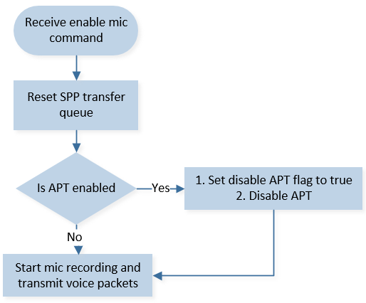
5.1 Flow Chart of Starting Mic Recording
Warning
Turning off APT before recording is required since voice over SPP and APT conflict.
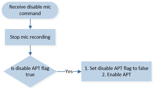
5.2 Flow Chart of Stopping Mic Recording
5.3 Data Formats of Command and Voice Packet
The microphone of the headset can be toggled on or off by dongle, which sends the necessary commands to inform the headset.
The command format is shown in the table below:
| Dongle requestes to turn on/off headset's microphone | |||
|---|---|---|---|
| Byte | Bit | Value | Notes |
| Byte 0 | ALL | 0x52 | Data start byte |
| Byte 1 | ALL | 0x01 | Date type (Command packet) |
| Byte 2 | ALL | 0x02 | Payload length |
| Byte 3 | ALL | 0x03 | Command type (Request to turn on/off microphone) |
| Byte 4 | ALL | 0x1 or 0x0 | 0x1: turn on microphone 0x0: turn off microphone |
| Byte 5 | ALL | 0x54 | Data stop byte |
The format of voice packet transmitted from Headset to dongle is shown below:
| Voice packets sent to gaming dongle | |||
|---|---|---|---|
| Byte | Bit | Value | Notes |
| Byte 0 | ALL | 0x52 | Data start byte |
| Byte 1 | BIT [0~1] | 0x00 | Date type (Voice packet) |
| BIT [2~7] | 0x0 | NOT used now | |
| Byte 2 | ALL | len | Payload length |
| Byte [3 ~ (len+2)] | ALL | voice data | Encoded microphone data from DSP |
| Byte (len+3) | ALL | 0x54 | Data stop byte |
5.4 Parameters of Voice Data
The voice data is encoded using SBC, and the SBC parameters are detailed in the table provided below:
| sample rate | 16k/32k (According to MCU config tool) |
| channel mode | Mono |
| block length | 16 |
| subband number | 8 |
| allocation method | Loudness |
| bitpool | 22 |
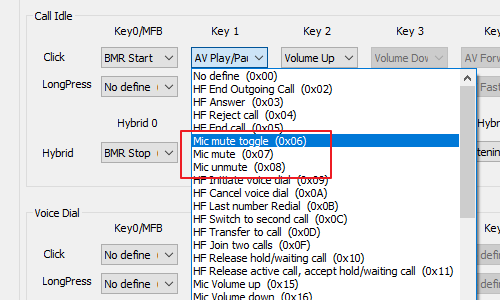
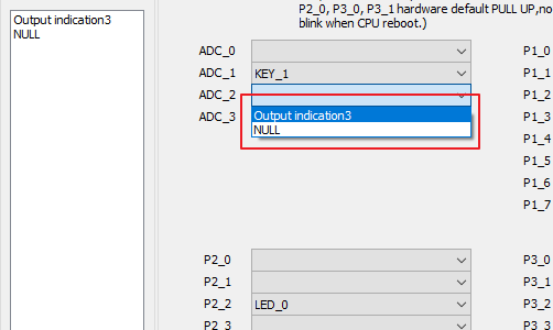
5.5 Microphone Mute/Unmute LED
This headset feature includes an LED that indicates the mute/unmute status of the microphone.
To toggle the microphone mute/unmute function, a key can be configured using the MCU config tool.
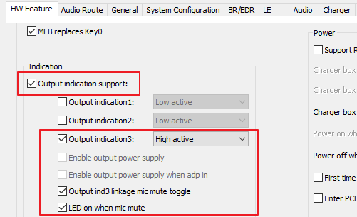
Additionally, this feature relies on output indication 3 to function properly.
In order to utilize this feature, the user needs to connect an LED to the pin assigned for output indication 3.
The pin will be pulled either high or low based on the setting when the microphone is muted or unmuted.
6 Low-Latency Gaming Mode
When the streaming device is a dongle, the headset will switch to low-latency gaming mode.
6.1 Enter/Exit Low-Latency Gaming Mode
The headset is responsible for initiating the entering and exiting of low-latency gaming mode.
The dongle will send the corresponding command to the headset.
It is expected that the headset will be in low-latency gaming mode when connected to a dongle as the streaming device.
6.2 Gaming Mode Command Format
The following tables outline the SPP data format for commands initiated by the headset and commands sent by the dongle, respectively.
| Command sent by headset | |||
|---|---|---|---|
| Byte | Bit | Value | Notes |
| Byte 0 | ALL | 0x52 | Data start byte |
| Byte 1 | ALL | 0x01 | Date type (Command packet) |
| Byte 2 | ALL | 0x02 | Payload length |
| Byte 3 | ALL | 0x02 | Command type (Request Gaming Mode) |
| Byte 4 | ALL | 0x1 or 0x0 | 0x1: Enter gaming mode 0x0: Exit gaming mode |
| Byte 5 | ALL | 0x54 | Data stop byte |
| Command sent by dongle | |||
|---|---|---|---|
| Byte | Bit | Value | Notes |
| Byte 0 | ALL | 0x52 | Data start byte |
| Byte 1 | ALL | 0x01 | Date type (Command packet) |
| Byte 2 | ALL | 0x02 | Payload length |
| Byte 3 | ALL | 0x01 | Command type (Set Gaming Mode) |
| Byte 4 | ALL | 0x1 or 0x0 | 0x1: Enter gaming mode 0x0: Exit gaming mode |
| Byte 5 | ALL | 0x54 | Data stop byte |
7 Game-Chat Volume Control
This feature allows users to adjust the volume of the game and chat individually.
Therefore, the dongle must support dual UAC.
The following tables outline the SPP data format for commands sent by the headset and commands sent by the dongle, respectively.
| Setting message sent by dongle | |||
|---|---|---|---|
| Byte | Bit | Value | Notes |
| Byte 0 | ALL | 0x52 | Data start byte |
| Byte 1 | ALL | 0x01 | Date type (Command packet) |
| Byte 2 | ALL | 0x04 | Payload length |
| Byte 3 | ALL | 0x06 | Command type (Set volume balance) |
| Byte 4 | ALL | 0x0: Ack 0x2: Update |
message type |
| Byte 5 | ALL | 0x0~ 0x64 | gaming volume level |
| Byte 6 | ALL | 0x0~ 0x64 | chat volume level |
| Byte 7 | ALL | 0x54 | Data stop byte |
| Notification message sent by dongle | |||
|---|---|---|---|
| Byte | Bit | Value | Notes |
| Byte 0 | ALL | 0x52 | Data start byte |
| Byte 1 | ALL | 0x01 | Date type (Command packet) |
| Byte 2 | ALL | 0x04 | Payload length |
| Byte 3 | ALL | 0x06 | Command type (Set volume balance) |
| Byte 4 | ALL | 0x1: Inform | message type |
| Byte 5 | ALL | 0x0~ 0x64 | gaming volume level |
| Byte 6 | ALL | 0x0~ 0x64 | chat volume level |
| Byte 7 | ALL | 0x54 | Data stop byte |
API:
app_dongle_update_volume_balance() is used to update volume balance information recorded in headset to dongle.
Parameters gaming_level and chat_level stand for the volume of game and the volume of chat respectively.
The range of gaming_level and chat_level is 0~100, which stands for 0% ~ 100%.
app_dongle_update_volume_balance(gaming_level, chat_level);
8 Dual-Mode
Enabling this feature will introduce two modes in the headset: 2.4G mode and BT mode.
2.4G mode: Headset can only be searched for and connected by the dongle.
BT mode: Headset can be searched for and connected by any Bluetooth-enabled device, except for the dongle.
Following tables summarize the combination and expected result.
| Headset | ||||
|---|---|---|---|---|
| Disable dual mode | Enable dual mode - 2.4G mode | Enable dual mode - BT mode | ||
| Dongle | Disable dual mode | Headset could be connected by dongle or other bluetooth devices | Not support this case | Not support this case |
| Enable dual mode | Not support this case | Headset ONLY could be connected by dongle | Headset could be connected by bluetooth devices except dongle | |
| Headset | ||||
|---|---|---|---|---|
| Disable dual mode | Enable dual mode - 2.4G mode only | Enable dual mode - 2.4G + BT mode | ||
| Dongle | Disable dual mode | Headset could be connected by dongle or other bluetooth devices | Not support this case | Not support this case |
| Enable dual mode | Not support this case | Headset ONLY could be connected by dongle | Headset could be connected by dongle or other bluetooth devices | |
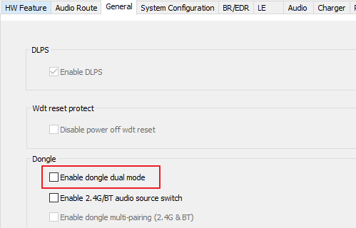
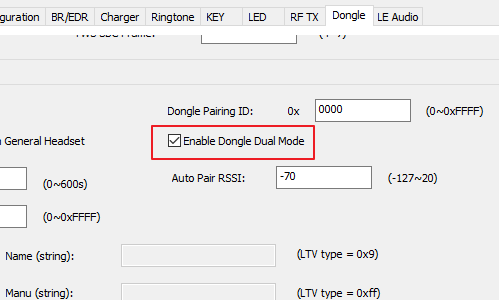
8.1 How to Setup Dual Mode
Users could find out option in MCU config tool.
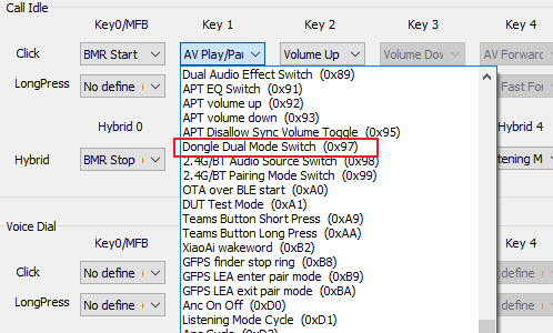
In order to switch mode, a key should be set in MCU config tool.
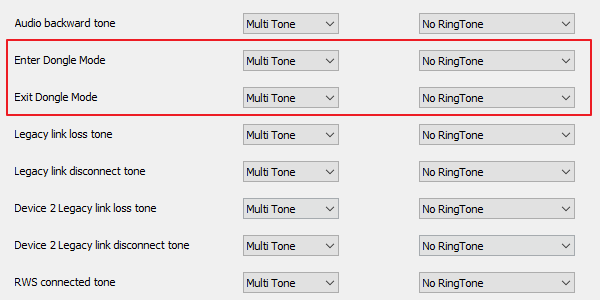
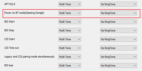
Besides, user could configure ringtones in MCU config tool.
It will help to distinguish headset in which mode.
8.2 Pre-pair Up Dongle and Headset
To optimize the pairing process, we offer a pre-pairing flow.
By inputting the last three bytes of the headset’s MAC address into the dongle, the dongle will only connect to the headset with the specified last three bytes MAC address.
This feature ensures a faster and more streamlined pairing process, as the dongle will automatically search and connect to the headset with the matching MAC address.
Users can simply input the last three bytes of the headset’s MAC address into the dongle once, and subsequent connections will be established seamlessly without the need for manual pairing.
//used to record last three bytes MAC addres for pre-pair up process
app_cfg_nv.saved_id
9 Dongle/BT Audio Source Switch
This feature allows users to specify which connected device they want to use to play media.
By designating a specific device, users have the ability to control and choose where their media is streamed and played.
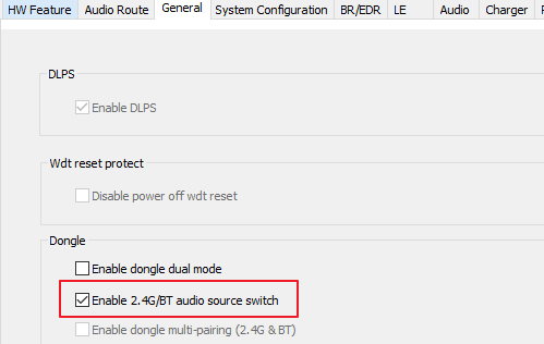
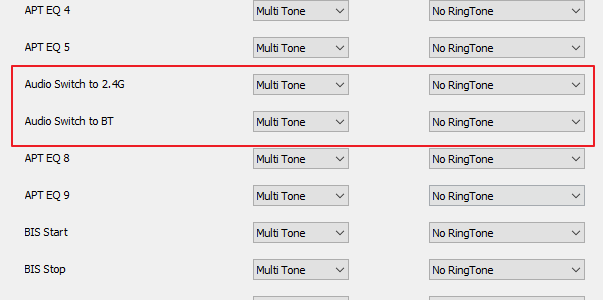
9.1 How to Setup Dongle/BT Audio Source Switch
Users could find out option in MCU config tool.
Warning
The option “Enable Multilink Support” in General Tab should be checked.
To define and set both F_APP_GAMING_DONGLE_SUPPORT and F_APP_24G_BT_AUDIO_SOURCE_CTRL_SUPPORT to 1 in app_flags.h, please follow these steps:
Open the app_flags.h file in your code editor.
Locate the section where the app flags are defined.
Find the line that sets F_APP_GAMING_DONGLE_SUPPORT and change its value to 1.
Find the line that sets F_APP_24G_BT_AUDIO_SOURCE_CTRL_SUPPORT and change its value to 1.
Save the changes made to app_flags.h.
Now, both F_APP_GAMING_DONGLE_SUPPORT and F_APP_24G_BT_AUDIO_SOURCE_CTRL_SUPPORT will be defined and set to 1 in app_flags.h.
#undef F_APP_GAMING_DONGLE_SUPPORT
#define F_APP_GAMING_DONGLE_SUPPORT                 1
#undef F_APP_24G_BT_AUDIO_SOURCE_CTRL_SUPPORT
#define F_APP_24G_BT_AUDIO_SOURCE_CTRL_SUPPORT      1
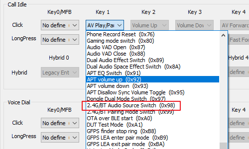
In order to switch source between dongle and BT device, a key should be set in MCU config tool.
Besides, user could configure ringtones in MCU config tool.
It will help users to distinguish source is selected to which device.
9.2 Implement Description
In order to achieve this feature, the headset would prioritize and connect only the AVRCP and A2DP profiles with the selected device.
For example, if the headset is currently connected to both a dongle and a Bluetooth device simultaneously, and the user selects the dongle as the allowed source, the headset would automatically disconnect the AVRCP and A2DP profiles from the Bluetooth device and establish connections for AVRCP and A2DP with the dongle.
Similarly, if the headset is not connected to two devices simultaneously, and the user presses a switch key to change the allowed source, the headset would still perform the corresponding action of disconnecting from the current device and establishing connections with the newly selected device for AVRCP and A2DP.
//used to records currently allowed audio source
app_cfg_nv.allowed_source

typedef enum
{
    ALLOWED_SOURCE_DONGLE   = 0x00,  // dongle
    ALLOWED_SOURCE_BT       = 0x01,  // other BT devices
} T_ALLOWED_SOURCE;
10 Dual Mode Multi-pairing
Enabling this feature would introduce two different pairing modes: 2.4G pairing mode and BT pairing mode.
Note
It is important to note that this feature only takes effect when the headset is in 2.4G + BT mode.
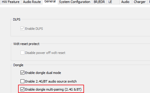
10.1 How to Setup Dual Mode Multi-pairing
Warning
The option “Enable Multilink Support” and “Enable Dongle Dual Mode” in General subtab should be checked.
To define and set both F_APP_GAMING_DONGLE_SUPPORT and F_APP_DONGLE_MULTI_PAIRING to 1 in app_flags.h, please follow these steps:
Open the app_flags.h file in your code editor.
Locate the section where the app flags are defined.
Find the line that sets F_APP_GAMING_DONGLE_SUPPORT and change its value to 1.
Find the line that sets F_APP_DONGLE_MULTI_PAIRING and change its value to 1.
Save the changes made to app_flags.h.
Now, both F_APP_GAMING_DONGLE_SUPPORT and F_APP_DONGLE_MULTI_PAIRING will be defined and set to 1 in app_flags.h.
#undef F_APP_GAMING_DONGLE_SUPPORT
#define F_APP_GAMING_DONGLE_SUPPORT     1
#undef F_APP_DONGLE_MULTI_PAIRING
#define F_APP_DONGLE_MULTI_PAIRING      1
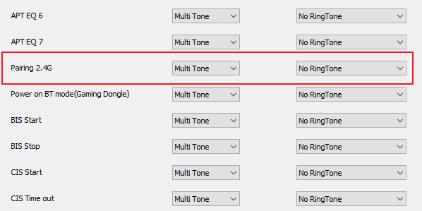
In order to switch pairing mode, a key should be set in MCU config tool.
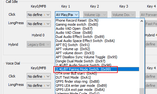
Besides, user could configure ringtones in MCU config tool.
It will help users to distinguish which pairing mode is currently activated.
10.2 More Description
If headset enters dongle pairing mode (default setting), users could switch to BT pairing mode via key.
It means users could select which kind of device could search and connect to headset.
| Headset | |||
|---|---|---|---|
| Dongle pairing mode | BT pairing mode | ||
| Device | Dongle | Dongle could find out and connect headset | Dongle could not find out headset |
| BT devices except dongle | BT devices could not find out headset | BT devices could find out and connect headset | |
When app_cfg_nv.is_bt_pairing is true, it means that the current activated pairing mode is BT pairing mode.
//used to records currently pairing mode
app_cfg_nv.is_bt_pairing