Quick Start
This document aims to guide users in quickly setting up the RTL8777G EVB development environment, including compiling the SDK, flashing firmware, upgrading firmware, and capturing logs. The RTL8777G SDK provides Matter/Thread-related modules, facilitating Matter vendors in the secondary development of Matter-related applications.
Environment
Prepare EVB
The RTL8777G EVB evaluation board offers a hardware environment for user development and application debugging. It includes a USB module for direct power supply and features both download and operating modes. Users need to use different wiring methods to set the EVB into the required mode.
Hardware Wiring
Download Mode
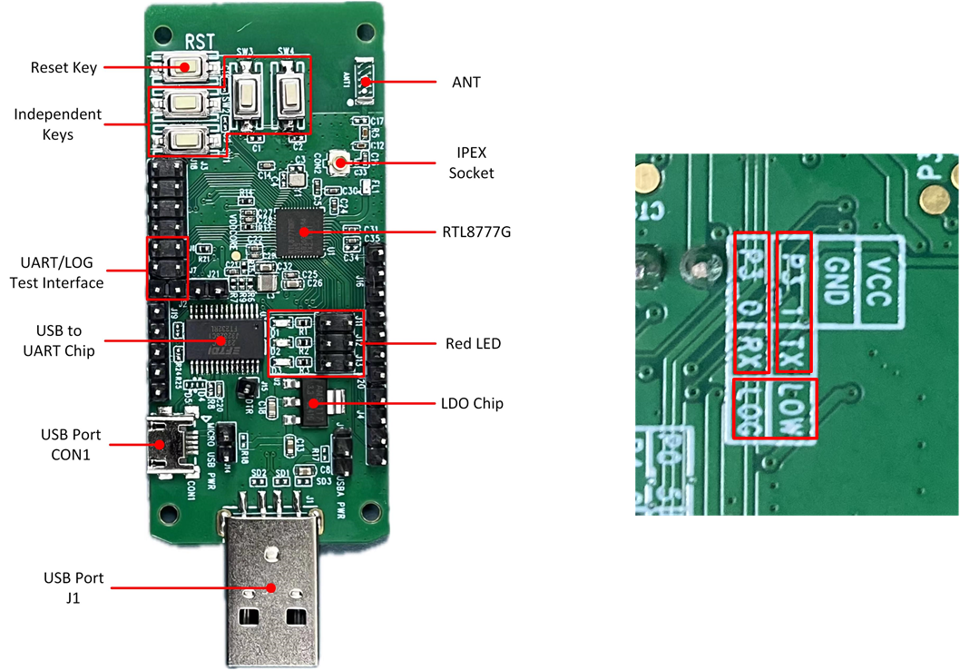
Download Mode Wiring Front (Left) Back (Right)
As shown in Download Mode Wiring (Left) short P3_1 and TX, short P3_0 and RX, Download Mode Wiring (Right) short LOW and LOG, then press button reset, entering Download Mode.
Note
The chip will read the level signal of the Log Pin after power-on. If the level is low, it will bypass the flash and enter programming mode. Otherwise, it will run the application layer program.
Normal Mode
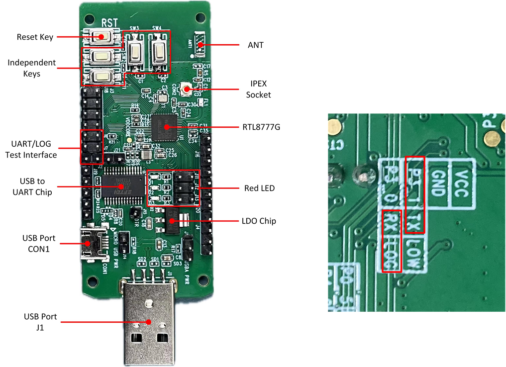
Normal Mode Wiring Front (Left) Back (Right)
As shown in Normal Mode Wiring Front (Left) Back (Right), disconnect LOW and LOG. Short RX and LOG, as shown in Normal Mode Wiring(right), then refer Log Verification
Configuration
For Demo Project, please use default configuration.
Building and Downloading
Building
Prepare openthread
$ cd ./subsys/openthread
Clone openthread in the current folder
$ git clone https://github.com/openthread/openthread
Prepare Matter
$ cd ./subsys/matter
Clone Matter source code in current folder:
$ git clone https://github.com/pankore/connectedhomeip
$ cd connectedhomeip/
$ git checkout sdk-v1.6.3.0
Setup Matter environment
$ cd ./subsys/matter/connectedhomeip/
$ git submodule update --init --recursive
$ source scripts/bootstrap.sh
$ source scripts/activate.sh
Build Matter lighting app
$ cd ./subsys/matter/samples
$ ./build.py rtl8777g lighting
Downloading
To ensure the EVB functions properly, users can follow these steps:
Prepare an EVB, confirm that the EVB interface wiring is correct (refer to Download Mode Wiring (Left) ), and set the EVB to download mode.
-
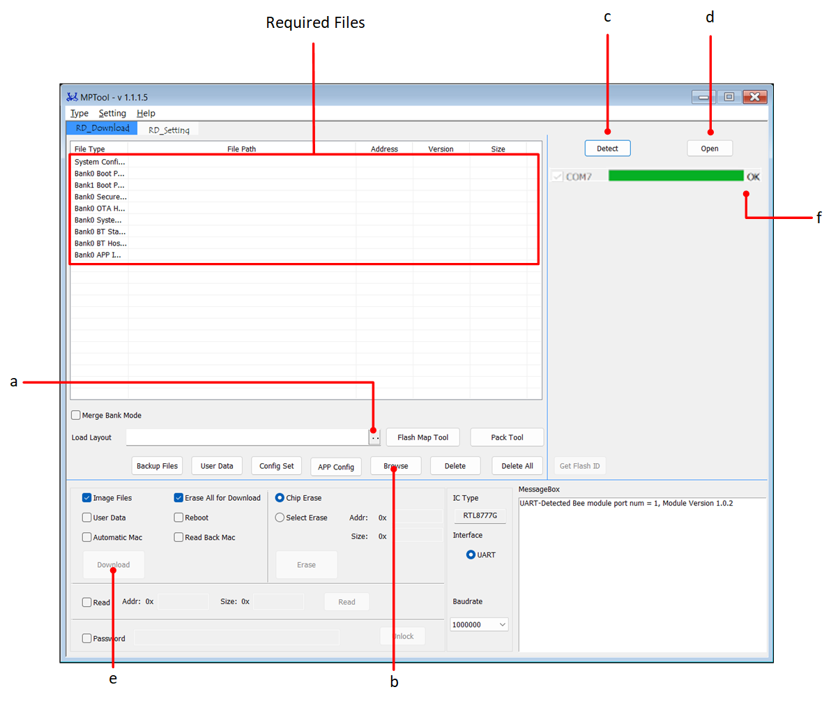
Double-click to run MP Tool.exe. Refer to MP Tool Downloading Menu. For detailed operation steps and file paths refer to MP Tool.
In Load Layout, click on .. to load the
flash_map.inifile.Click Browse to load all the flashing files, as shown in RTL8777G default downloading file.
Click Detect to successfully identify the COM port of the EVB.
Click Open to successfully open the COM port.
Click Download to start the downloading process; the progress bar will display the current progress.
The progress bar showing OK indicates that the downloading process was successful.
MP Tool Downloading Menu
After the program downloading is completed, set the EVB to Normal mode. (Refer to Normal Mode)
Observe the EVB behavior (whether the LED blinks, or the phone searches for Bluetooth Low Energy broadcasts, etc., based on the actual function of the user's APP Image), or check whether the logs on the SoC side meet expectations.
Preparing Files
EVB can function properly only after multiple files are downloaded, including foundational files and application files. The foundational files encompass the firmware and configuration settings required by RTL8777G, while the application files include the specific code and functionality implementations of the target project.
The default downloading file for the RTL8777G is shown as RTL8777G default downloading file. For further details, please refer to RTL87x2G Default Downloading Files Instructions.
File |
Given by Realtek |
File type |
|---|---|---|
System Config File |
(Generated by MP Tool) |
Basic file |
Bank0 Boot Patch Image |
√ |
Basic file |
Bank0 OTA Header File |
(Generated by MP Tool) |
Basic file |
Bank0 System Patch Image |
√ |
Basic file |
Bank0 Bluetooth Stack Patch Image |
√ |
Basic file |
Bank0 Bluetooth Host Image |
√ |
Basic file |
Bank0 APP Image |
(Compiled by tools) |
Application file |
No. |
File |
Instruction |
|---|---|---|
1 |
System Config File |
This file is used to configure various parameters and settings related to the device, such as the Bluetooth address, the number of links, and other relevant configurations. For more information about parameter settings, please refer to RTL87x2x MP Tool User Guide. |
2 |
Boot Patch Image |
The Boot Patch Image includes the Bank0 Boot Patch Image and the Bank1 Boot Patch Image. The ROM code reserves the Patch function entry point, which can be used to optimize the Boot flow, modify the behavior of the secure ROM code, and expand the functionality of the ROM code. |
3 |
Bank0 OTA Header File |
It is a file that defines the layout of the Flash Bank. |
4 |
Bank0 System Patch Image |
The ROM code reserves the Patch function entry point, which allows modifications to the behavior of the non-secure ROM code and the expansion of ROM code functionality. |
5 |
Bank0 BT Stack Patch Image |
That supports features related to the BT Controller stack. |
6 |
Bank0 BT Host Image |
That implements the BLE Upper stack. |
7 |
Bank0 APP Image |
It is compiled from Keil/GCC project and processed using tools like fromelf. |
Note
Boot Patch Image/System Patch Image/Bluetooth Host Image/Bluetooth Stack Patch Image are provided directly by Realtek.
Users can download the above materials through Anchor (Realtek's file release system). If an Anchor account is not available, please apply for registration through an agent/PM/FAE, or directly download from RealMCU .
NOTE:
Please store the SDK, tools, and other materials in a non-Chinese path without spaces.
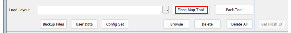
Before downloading the file, the
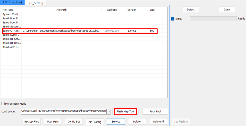
flash_map.inifile must be loaded first. Theflash_map.iniis the generated flash layout, which can be understood as the address allocation of each part in the flash. It can be directly generated by clicking Flash Map Tool on the MP Tool interface, as shown in Flash Map Tool.
Flash Map Tool
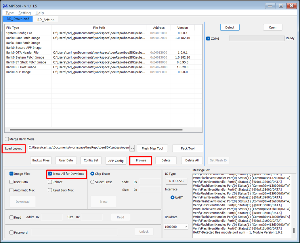
When selecting Erase All for Download during the download process, it will completely erase the flash before starting the writing process. If not selected, only the necessary files for downloading will be erased, as shown in Erase All for Download.
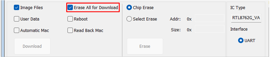
Erase All for Download
Flash Map
To generate the flash map.ini file, users can choose from the following two methods:
-
Method 1: Use MP Tool and click on Flash Map Tool. The interface will navigate to Flash Map Generate Tool. Then use Method 2.File path:
RTL87x2G-SDK-Matter-vx.x.x\tools\BeeMPTool_vx.x.x.x\BeeMPTool\FlashMap\flash map.ini
-
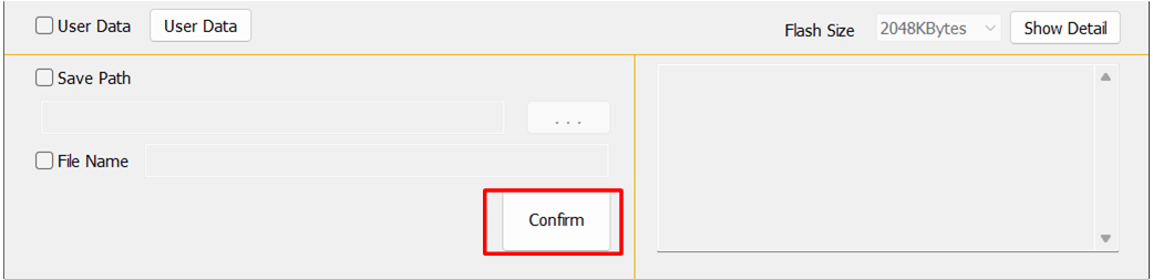
Method 2: Directly use Flash Map Generate Tool and click Confirm to generate the
flash map.inifile, as shown in Flash Map Generate Tool.Tool path:RTL87x2G-SDK-Matter-vx.x.x\tools\BeeMPTool_vx.x.x.x\BeeMPTool\tools\FlashMapGenerateTool.exeFile path:RTL87x2G-SDK-Matter-vx.x.x\tools\BeeMPTool_vx.x.x.x\BeeMPTool\tools\flash map.ini
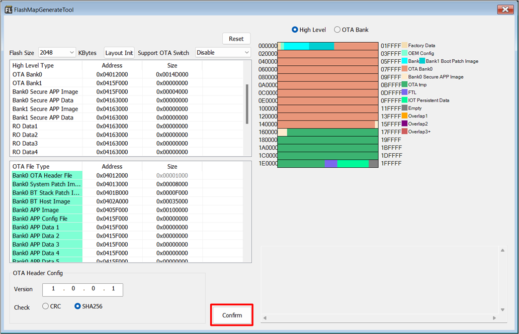
Flash Map Generate Tool
NOTE:
In the Flash Map Generate Tool interface, click on the dropdown option Flash Size. The user can select the appropriate Flash Size based on actual usage, as shown in Flash Size .
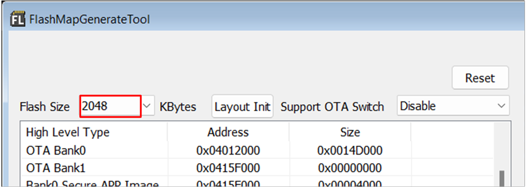
Flash Size
Users can modify the Flash Layout according to their actual needs. Click Layout Init to adjust the size of each area. After confirming, click Confirm.
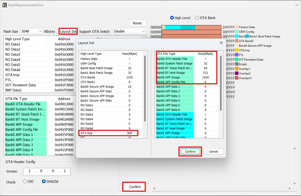
Flash Layout
When generating the flash map.ini file using Method 1 and Method 2, a
flash_map.hfile will also be created. Please copy theflash_map.hfile to the appropriate path to generate the correct load address for use by the Bank0 APP Image. For more detailed information, please refer to the document Memory .
Path for the flash_map.h file generated by Method 1 : RTL87x2G-SDK-Matter-vx.x.x\tools\BeeMPTool_vx.x.x.x\BeeMPTool\FlashMap\flash_map.h
Path for the flash_map.h file generated by Method 2 : RTL87x2G-SDK-Matter-vx.x.x\tools\BeeMPTool_vx.x.x.x\BeeMPTool\tools\flash_map.h
Note
Copy the generated
flash_map.hto theflash_map.hpath during the Matter project build:RTL87x2G-SDK-Matter-vx.x.x\subsys\openthead\vendor\rtl87x2g\8777g\flashmap.hIt is recommended to keep the default configuration for
flash_map.h
OTA Header
Open MP Tool, click Flash Map Tool, and the interface will switch to Flash Map Generate Tool. Click Confirm to generate flash map.ini, and an OTA Header File will also be generated simultaneously. Path: RTL87x2G-SDK-Matter-vx.x.x\tools\BeeMPTool_vx.x.x.x\BeeMPTool\OTAHeader
OTA Header File
System Config File
Using MP Tool, click Config Set to adjust relevant parameters in the Config Setting interface. After clicking Confirm, the System Config File will be generated and loaded into the corresponding area, as shown in System Config File. For novice users, it is recommended to keep the default settings in the Config Setting interface.
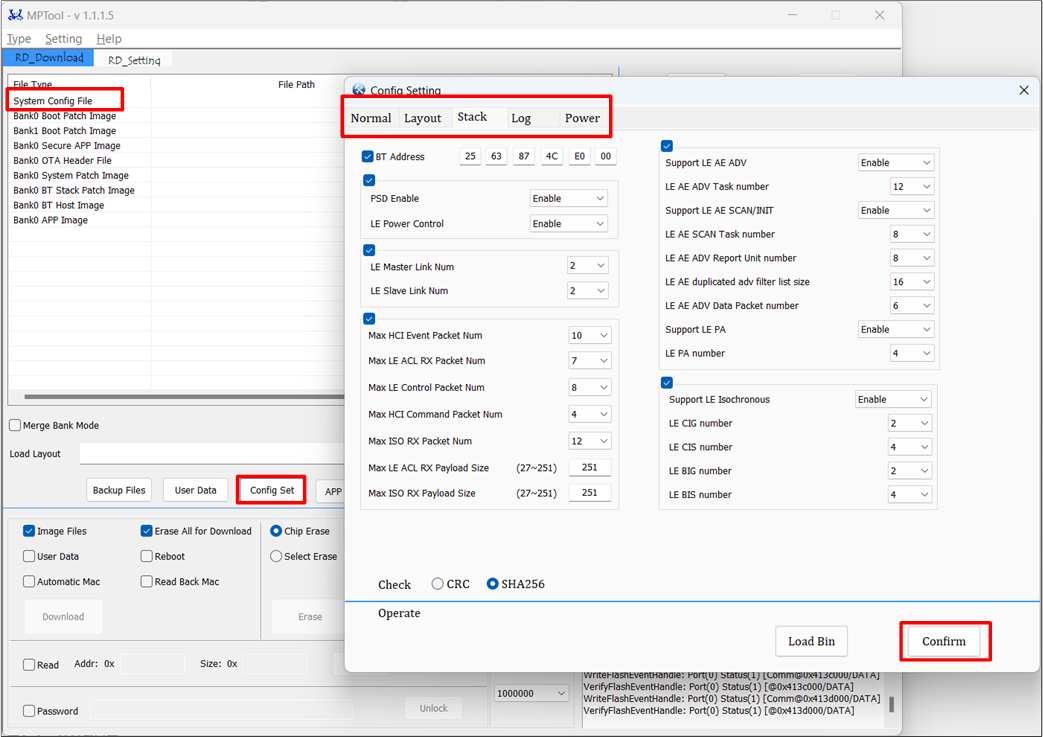
System Config File
APP Image
All matter applications in the SDK are compiled using Ubuntu GCC. The default output path is: \subsys\openthread\build\bin\matter-cli-ftd_bank0_MP_DEV_XXX.bin. It is generally not recommended for users to create new projects for development; instead, they should open existing example projects and add functionality on that basis.
MP Tool
Refer to Download Mode, put the EVB into download mode, and then the user can use MP Tool to download the program onto the device.
Path: RTL87x2G-SDK-Matter-vx.x.x\tools\BeeMPTool_vx.x.x.x, with software version not lower than V1.1.0.x.
Double-click to run MP Tool.exe
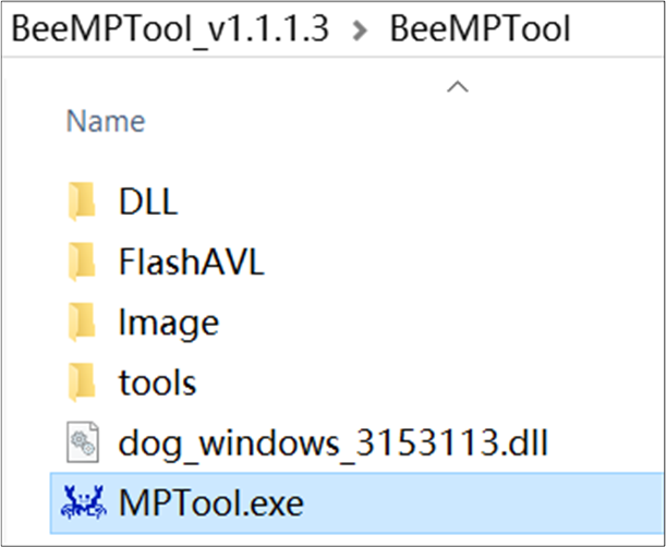
MP Tool.exe
Select Chip Type: RTL8777G
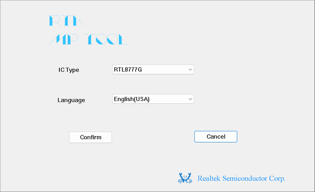
MP Tool Chip Selection
-
Type: Debugging, as shown in MP Tool Mode Selection.MP Tool supports two Downloading modes:a. Mass Production Mode: For production line manufacturingb. Debugging Mode: For use by developers during development and debugging
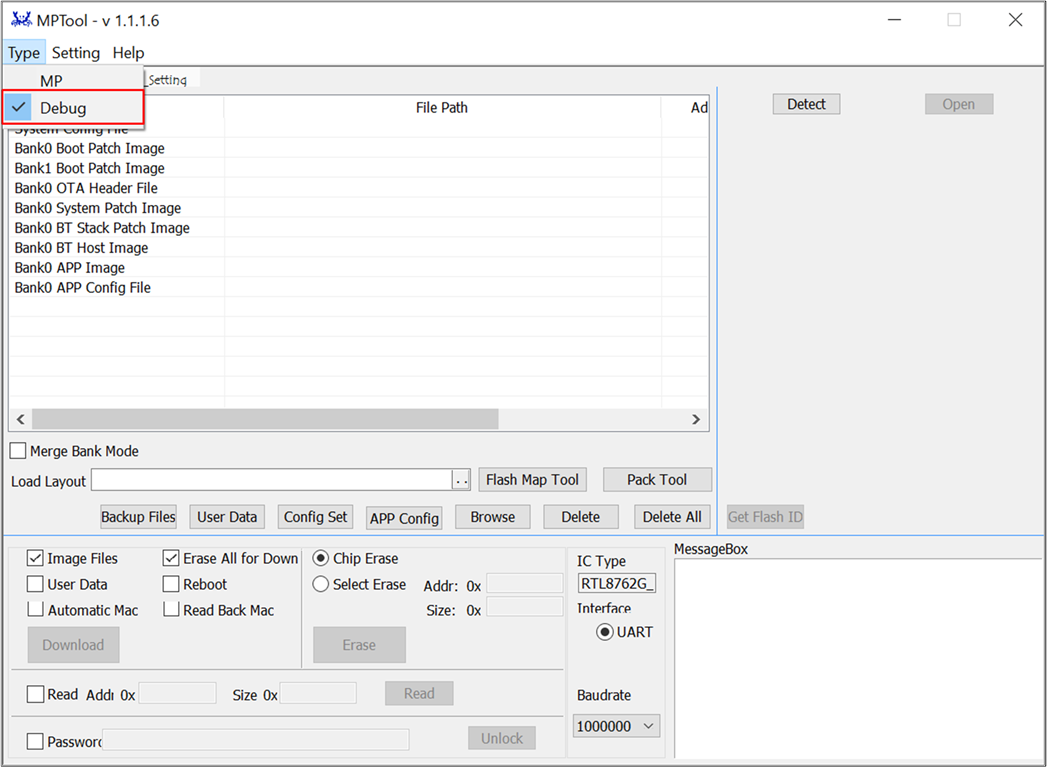
MP Tool Mode Selection
-
In the interface, click the Load Layout button and load the
flash_map.inifile.Path:RTL87x2G-SDK-Matter-vx.x.x \subsys\openthread\vendor\rtl87x2g\8777g\flash map.ini, as shown in MP Tool programming interface. -
Click Browse to load all programming files, as shown in MP Tool programming interface. The file types and corresponding filenames are listed in Table of Corresponding Download File Type Names.
Note
MP Tool can download single or multiple files.
If only programming a single file, such as the Bank0 APP Image, DO NOT SELECT Erase All for Download in the figure.
File type |
File name |
File path |
|---|---|---|
System ConfigFile |
configFile_xxx.bin |
\subsys\openthread\vendor\rtl87x2g\rtl8777g\firmware\trustzone_disable |
Bank0 Boot PatchImage |
BANK0_boot_patch_MP_release_xxx.bin |
\subsys\openthread\vendor\rtl87x2g\rtl8777g\firmware |
Bank0 OTA HeaderFile |
OTAHeader_Bank0_xxx.bin |
\subsys\openthread\vendor\rtl87x2g\rtl8777g\firmware\trust_zone_disable |
Bank0 SystemPatch Image |
sys_patch_MP_release_xxx.bin |
\subsys\openthread\vendor\rtl87x2g\rtl8777g\firmware |
Bank0 Bluetooth StackPatch Image |
bt_stack_patch_MP_master_xxx.bin |
\subsys\openthread\vendor\rtl87x2g\rtl8777g\firmware |
Bank0 Bluetooth HostImage |
bt_host_MP_xxx.bin |
\subsys\openthread\vendor\rtl87x2g\rtl8777g\firmware |
Bank0 APP Image |
matter-cli-ftd_xxx.bin |
\subsys\openthread\vendor\rtl87x2g\rtl8777g\firmware\trustzone_disable |
MP Tool programming interface
Click Detect, and the interface will display the detected device's COM port, as shown in MP Tool COM Port Detection.
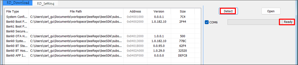
MP Tool COM Port Detection
Click Open. If the COM port opens successfully, "OK" will appear to the right of the progress bar; otherwise, "Fail" will be shown, as depicted in MP Tool COM Port Recognition Success. If it displays "Fail", users can refer to common errors for troubleshooting, then repeat the steps and click Detect and Open.
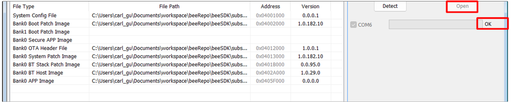
MP Tool COM Port Recognition Success
Common Mistakes as Follows
Check if the serial port Tx/Rx are reversed.
Check if the device P0_3 (Log Pin) is grounded before powering on.
Check if the serial adapter board supports 1M baud rate.
Check if the COM port is occupied.
-
If the serial port opens successfully, click Download. The progress bar to the right of the COM port will display the current download progress, as shown in MP Tool Download Process.
After the download is complete, "OK" will be displayed, as shown in MP Tool Successful Download.
If "Fail" is displayed, press the Reset button on the EVB or power cycle the EVB and repeat the above steps.
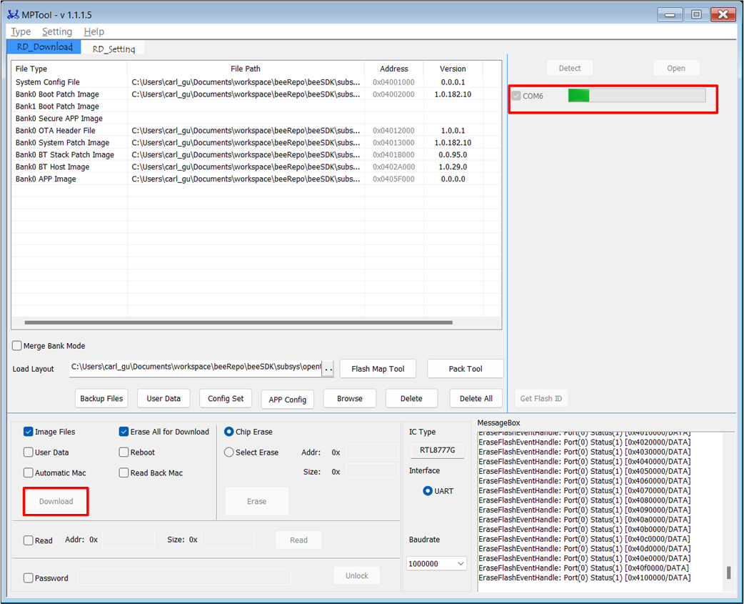
MP Tool Download Process
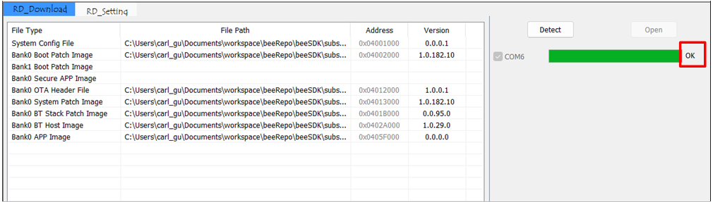
MP Tool Successful Download
MP Pack Tool
Users can use the MP Pack Tool to package upgrade files for devices, typically used for mass production or OTA. If in the early development and debugging stage, skip this section. Path: RTL87x2G-SDK-Matter-vx.x.x\tools\BeeMPTool_vx.x.x.x\BeeMPTool\tools\MPPackTool.exe.
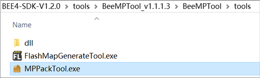
MP Pack Tool.exe
-
Double-click to run MP Pack Tool.exe in MP Pack Tool Interface (as shown in Bank0 Boot Patch Image & Bank0 APP Image)
Select IC Type: RTL8762G_VB
Choose ForOTA
Click Browse
Select the file to be upgraded.
Note
The size of the file to be upgraded must not exceed the size of the OTA Tmp area (refer to
flash_map.hin the project). If the total size of the files to be upgraded exceeds the size of the OTA Tmp area, package and upgrade them in batches.Since Patch, Stack, and other files are rarely updated, users generally only need to package the APP Image separately.
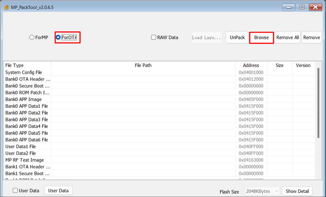
MP Pack Tool Interface
-
Once the file is loaded, click Confirm to generate the
ImaPacketFile.binfile, as shown in MP Pack Tool File Packaging Confirmation and Generated Package File.Path:RTL87x2G-SDK-Matter-vx.x.x\tools\BeeMPTool_vx.x.x.x\BeeMPTool\tools\ImaPacketFile.binNote
If "save patch" is checked, select the save directory for the OTA file; if not checked, it will be saved in the root directory by default.
MP Pack Tool File Packaging Confirmation
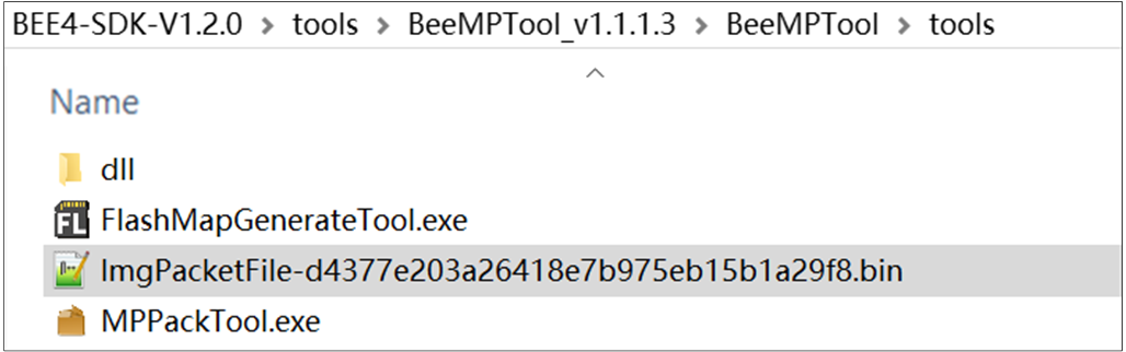
Generated Package File
Example Verification
App Verification
After programming the sample to the EVB board, it can be tested with single light control.
First, refer to Commissioning the Device to commission the device to the Matter network.
Then, complete the following steps:
-
Check on-off attribute value before toggle command
$ ./chip-tool onoff read on-off <node_id> <endpoint_id>
<node_id>: user-defined ID of the commissioned node.<endpoint_id>: ID of the endpoint with OnOff cluster implemented.
For example:
$ ./chip-tool onoff read on-off 2 1
The following message will appear in logs:
CHIP:TOO: OnOff: False -
Toggle the OnOff attribute state.
$ ./chip-tool onoff toggle <node_id> <endpoint_id>
For example:
$ ./chip-tool onoff toggle 2 1
-
Check on/off attribute value has changed after toggle command.
$ ./chip-tool onoff read on-off <node_id> <endpoint_id>
For example:
$ ./chip-tool onoff read on-off 2 1
The following message will appear in logs:
CHIP:TOO: OnOff: True
Log Verification
Users can capture and analyze SoC logs by using Debug Analyzer.
Path: RTL87x2G-SDK-Matter-vx.x.x\tools\DebugAnalyzer-vx.x.x.x
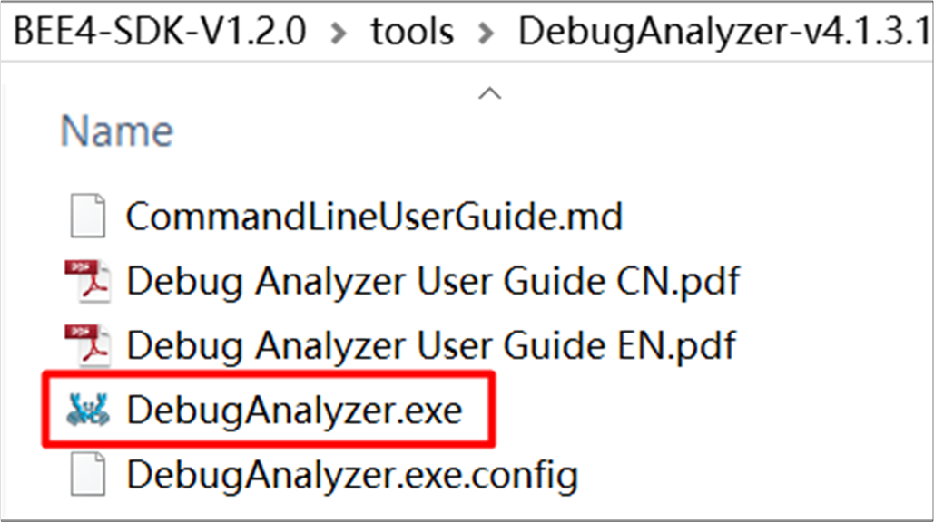
Debug Analyzer.exe
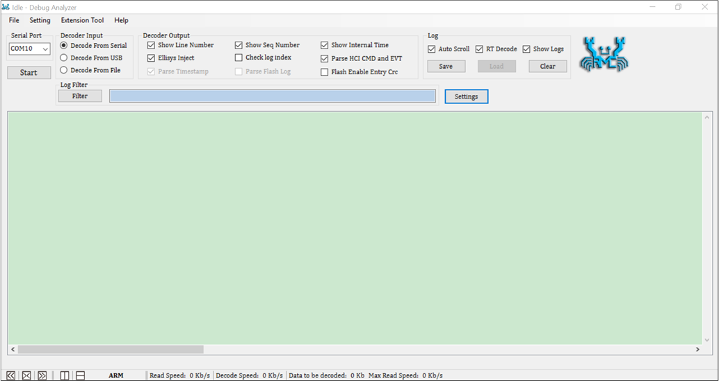
Double-click Debug Analyzer.exe, click on Setting, the default Baud rate is 2M, load the corresponding project's
.tracefile in App Trace File. Path:RTL87x2G-SDK-Matter-vx.x.x\download_images\ble_peripheral\app.trace, finally click Confirm to confirm the settings.
Debug Analyzer Parameter Settings Interface
Select the correct Serial Port, click Start, Debug Analyzer will start working. The PC will save the captured raw data in a
.binfile and, based on user settings in the.tracefile, will parse the raw data into plaintext logs, which will be saved in a.logfile. The log from the program run is shown in Debug Analyzer Captured Log.
Note
Default save path: The DataFile folder in the same directory as Debug Analyzer.exe, as shown in Soc Log save path.
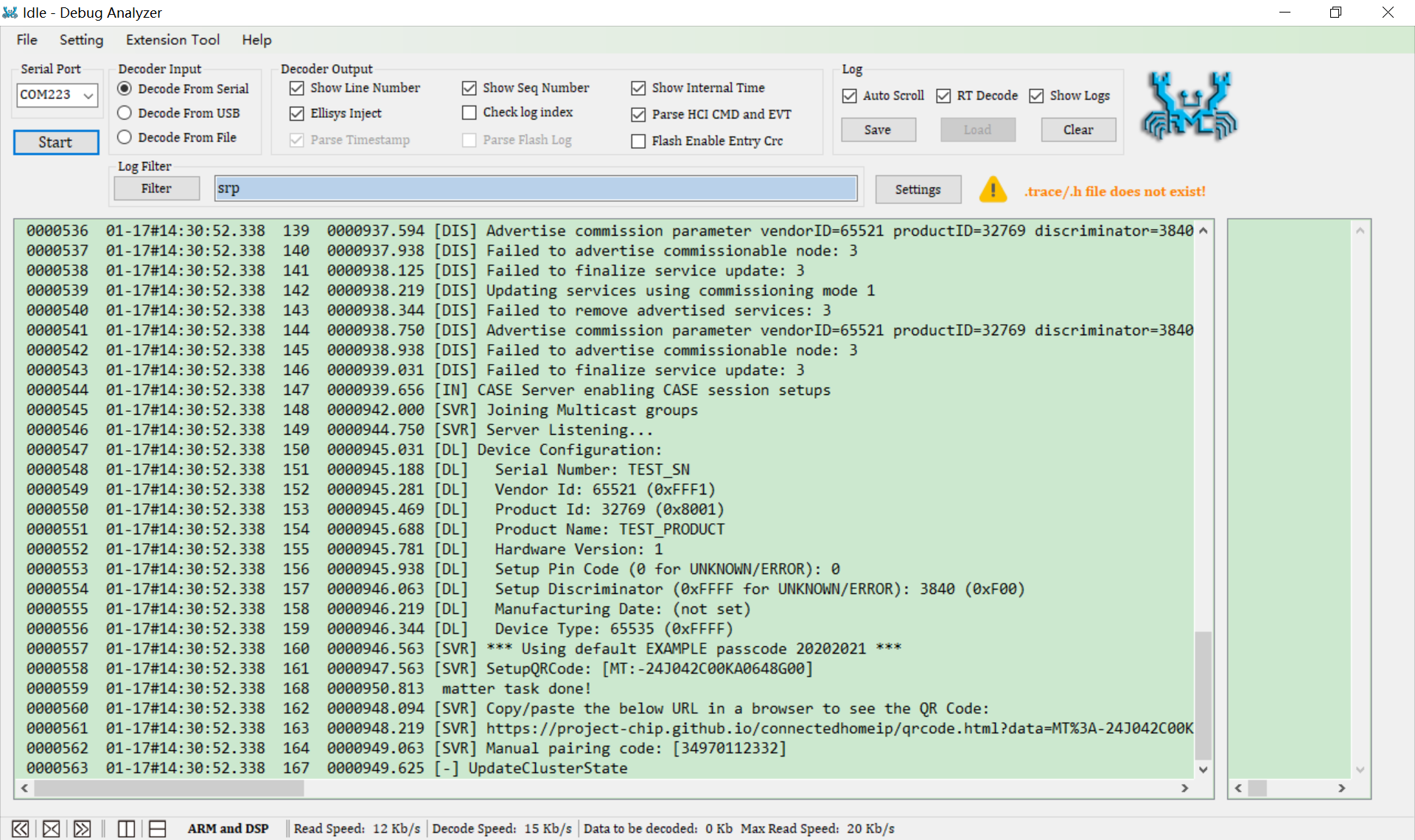
Debug Analyzer Captured Log
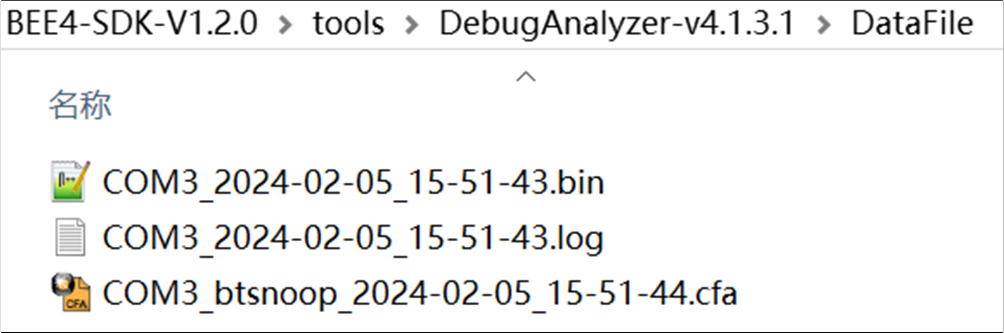
Soc Log save path
Note
Ensure that the
.tracefiles match the code running on the current SoC.If any issues are encountered during development, please provide the
.log.bin.cfaand.tracefiles located in theDebugAnalyzerDataFilepath so that Realtek can analyze and identify the issue.