Dashboard
This document aims to guide users in quickly setting up a development environment, including compiling the SDK, flashing firmware, upgrading firmware, and capturing Logs. Users can download the test files from the SDK to ensure that the EVB (Evaluation Board) functions properly and is compatible with the development environment.
The Reallek RTL8772GWP Dashboard SDK provides commonly used basic features such as vehicle speed monitoring, GUI framework, and message distribution. Additionally, the SDK offers easily expandable API interfaces, facilitating secondary development for Dashboard manufacturers.
Note
The Dashboard example described in this document uses the Reallek RTL8772GWP chip, paired with the EK9716 RGB (800 by 480) display screen. If developers choose to use the default hardware environment described in this document, they can directly run the example project.
If you need to adapt to other models of display screens, please refer Port Adaptation LCD for re-adapting the LCD screen driver.
Additionally, the Reallek RTL8772GWP chip supports display screen interfaces: I8080, QSPI/SPI, RGB888/RGB565, but does not support MIPI interface.
Practical Application Case
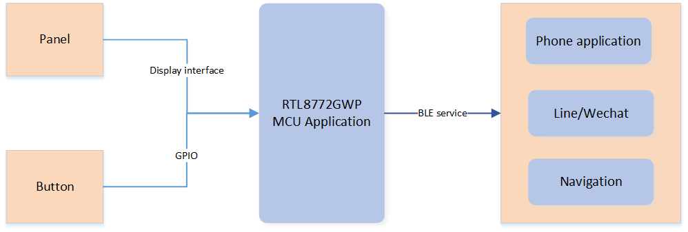
The following diagram illustrates the modules included in the Dashboard application:
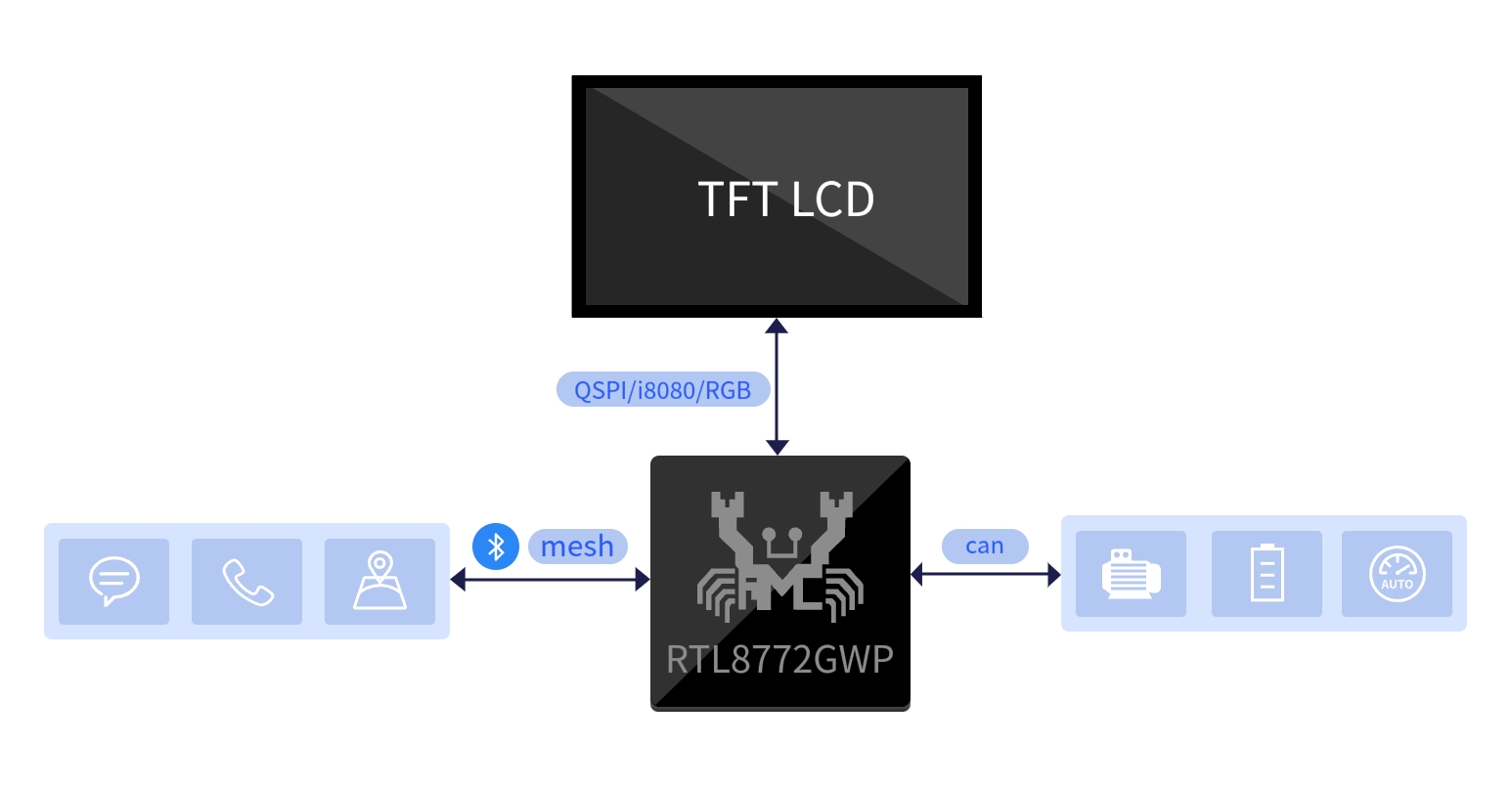
Dashboard Application Modules
The following diagram presents an overview of the modules included in the Dashboard application, it consists of a motherboard, a daughterboard, an LCD screen and a CAN module.
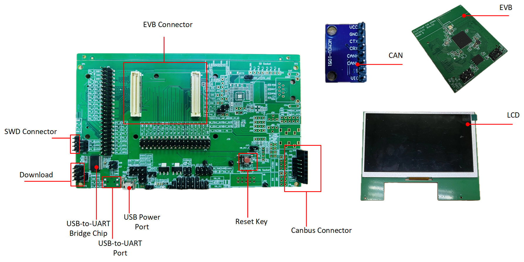
Dashboard Application Case
Supported Features
Reallek dashboard application provides complete support for the dashboard features.
Supports USB 3.0/2.0
Supports CAN communication
Supports the dashboard feature
Supports OTA (Over-the-Air) software upgrade
Supports incoming call notification and message pop-up feature
The RTL8772GWP supports the Bluetooth LE 5.3 specification and has a wide power supply range of 1.8V to 3.3V, giving developers more flexibility in selecting compatible peripherals.
Requirements
ARM Keil MDK: https://developer.arm.com
MPTool: RealMCU
DebugAnalyzer: RealMCU
Image Convert Tool: https://docs.realmcu.com/HoneyGUI/en/latest/tool/index.html
Note
For more detailed usage, please refer to Quick Start.
Different platforms support different panel interfaces, and developers must rely on the functionality of the IC platform to select the appropriate panel. LCD Hardware Platforms the supported interfaces for each platform.
Hardware Platforms |
Display Interface |
|---|---|
RTL8772GWP HDK |
I8080, QSPI/SPI, RGB888/RGB565 |
Wiring
The EVB evaluation board provides a hardware environment for user development and application debugging. The EVB consists of a main board and a daughter board. It has download mode and working mode, and users need to use different wiring methods to set the EVB into the desired mode.
RTL8772GWP EVB Port
EVB Power Supply Wiring, both the USB interfaces of user CON1 and CON2 need to be connected to a computer to provide power to the EVB.
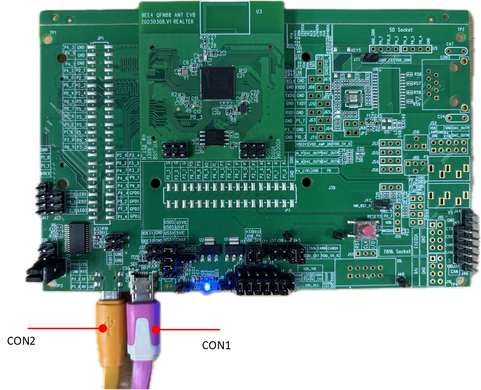
EVB Power Supply Wiring
Downloading Mode
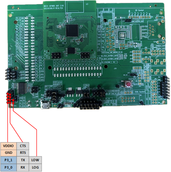
UART-USB Wiring
Short P3_1 and Tx , short P3_0 and Rx, short Low and Log, then press reset button to enter download programming mode.
Note
After power-on, the chip will read the logic level signal of the Log Pin. If the level is low, it will bypass the flash and enter programming mode; otherwise, it will run the application layer program.
Working Mode
To ensure the normal operation of the EVB, it is necessary to disconnect the shorting between Low and Log.
Log Wiring
Connect Rx and Log using a jumper cap.
Software Configuration and Environment
The software environment that needs to be configured includes:
Keil/gcc (to generate APP image)
Log tool (to analyze code execution)
MP tool (to generate System Config and OTA Header image files)
Dashboard APK (third-party tool for testing)
Image Convert Tool (to convert image resources into binary files compatible with RTK GUI recognition)
For specific usage, please refer to Tools.
Image Convert Tool
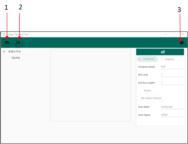
Image Convert Tool
Import the directory to be converted.
Set the conversion format: Choose whether to compress, output image color space format, output image properties (png, bmp, jpg), output image save location, and other parameters.
Convert the images.
Dashboard APK
The Bluetooth device name of the demonstration board is BLE_DASHBOARD .
Click Connect Device
Select BLE_DASHBOARD
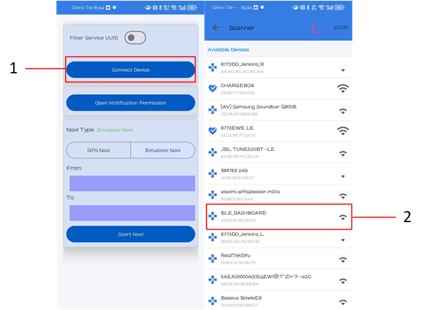
Dashboard APK Device Connection
Note
To test the message popup functionality, make sure that your Bluetooth connection is established. If you encounter any unresponsive message popups, check the Log for any relevant message-related entries. If you don't see any message-related Logs, you can try resetting the Dashboard option in the Open Notification Permission section of the main interface by toggling it off and then on again.
GUI Simulator
Simulator Setup Steps:
Configure the simulator environment. Refer to: Environment Setup Guide
Launch the simulator by opening
SDK/subsys/HoneyGUI.code-workspacein your IDE.-
Modify the configuration file
SDK/subsys/gui/win32_sim/menu_config.h:Enable 800x480 resolution: Uncomment the macro
CONFIG_REALTEK_BUILD_GUI_800_480Disable default demo: Comment out the macro
CONFIG_REALTEK_BUILD_GUI_454_454_DEMO
Compile and run the GUI simulator for debugging.
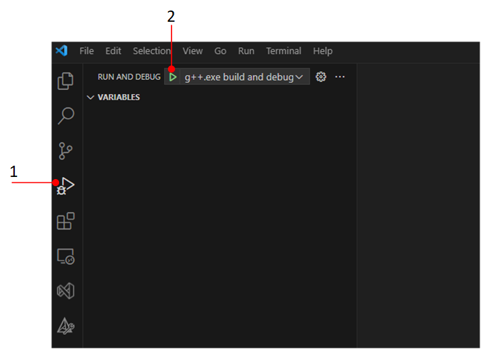
GUI Debug and Run the Simulator
Simulator running effect, GUI Simulator Running Effect.
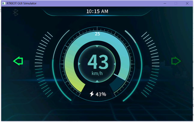
GUI Simulator Running Effect
LCD
The RTL8772GWP chip supports RGB mode LCD. Users do not need to write screen drivers from scratch, they can drive LCD screens with just a few simple steps. The RGB signal of RTL8772GWP is a fixed pin and cannot be mapped arbitrarily. There is only one set, as shown below. In the demonstration project, we will use the EK9716 display driver in the RGB888 interface, with a panel size of 800 x 480 as the target display. The input format will be RGB565 and the output format will be RGB888.
#define LCDC_DATA23         P5_0
#define LCDC_DATA22         P5_1
#define LCDC_DATA21         P5_2
#define LCDC_DATA20         P5_3
#define LCDC_DATA19         P5_4
#define LCDC_DATA18         P5_5
#define LCDC_DATA17         P3_5
#define LCDC_DATA16         P3_4
#define LCDC_DATA15         P3_3
#define LCDC_DATA14         P3_2
#define LCDC_DATA13         P9_2
#define LCDC_DATA11         P4_6
#define LCDC_DATA10         P4_5
#define LCDC_DATA9          P4_4
#define LCDC_DATA8          P1_2
#define LCDC_DATA12         P4_7
#define LCDC_DATA6          P4_2
#define LCDC_DATA5          P4_1
#define LCDC_DATA7          P4_3
#define LCDC_DATA4          P4_0
#define LCDC_DATA3          P0_7
#define LCDC_DATA2          P0_6
#define LCDC_DATA1          P0_5
#define LCDC_DATA0          P0_4

#define LCDC_RGB_WRCLK      P0_2
#define LCDC_HSYNC          P1_5
#define LCDC_VSYNC          P0_1
#define LCDC_CSN_DE         P0_0

#define LCDC_RESET          P2_2
Configurations
The default configuration of the dashboard feature in the SDK is as follows:
-
CONFIG_REALTEK_BUILD_GUI (on)Used to open GUI demo in HoneyGUI.
-
CONFIG_REALTEK_BUILD_GUI_800_480_DEMO (on)Enable building upper-level demo related files.
-
CONFIG_REALTEK_BUILD_LVGL_GUI (off)By default, RTK GUI demo is executed. If you need to switch to LVGL demo, you need to turn on
CONFIG_REALTEK_BUILD_LVGL_GUIinmenu_config.h(set to1), and addENABLE_LVGL_GUImacro definition in Keil precompilation. -
CONFIG_REALTEK_BUILD_SCRIPT_AS_A_APP (off)If you need to use the RVD tool for UI layout, you need to open the
CONFIG_REALTEK_BUILD_SCRIPT_AS_A_APPmacro definition (uncomment it). -
CONFIG_REALTEK_BUILD_PPE (on)Enable hardware accelerated Pixel Process Engine (PPE1.0), image effects processing (scaling, transparency, pixel convert processing, etc.).
-
CONFIG_REALTEK_CAN (off)Build CAN related project files.
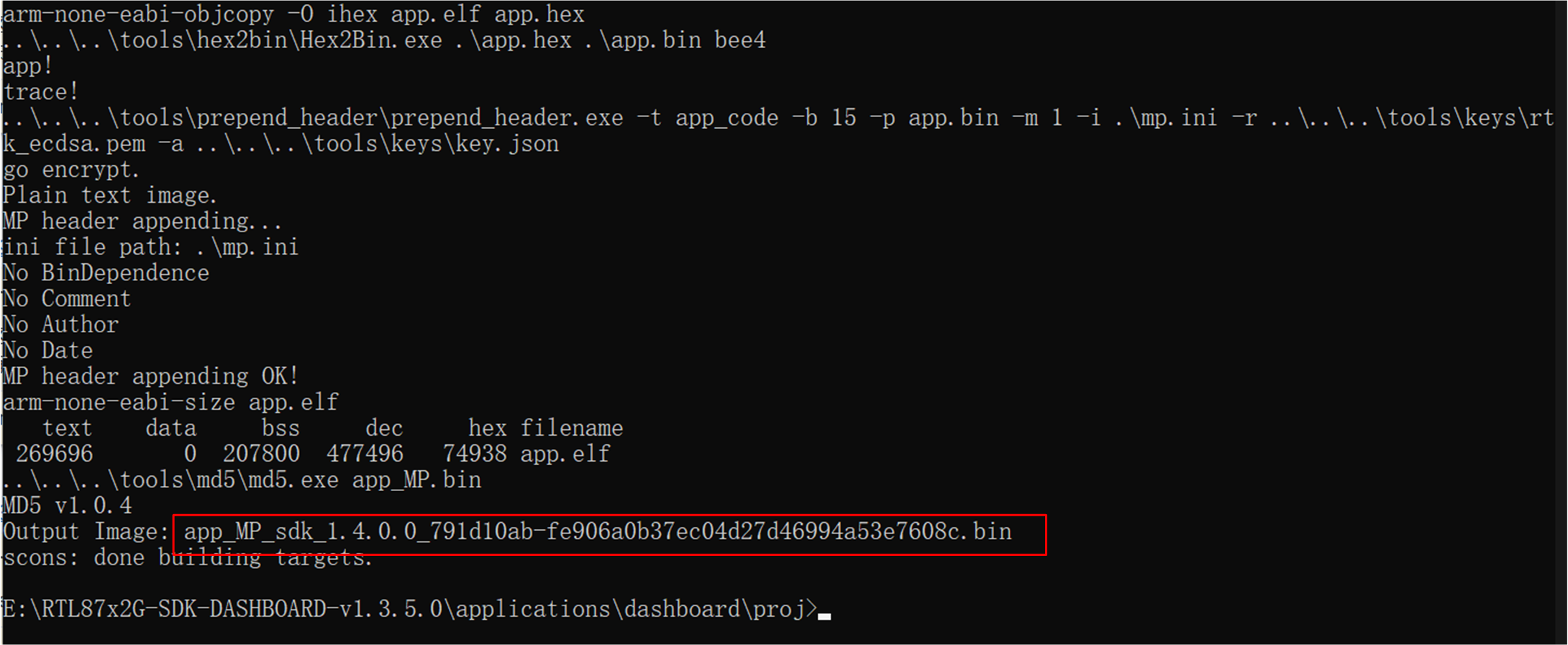
Scons Construction Project
Enable related macros in the
menu_config.hfile. For example, to build a CAN project, enableCONFIG_Reallek_CANand set it to1Run the cmd command in the proj directory: scons --target=MDK5. The run is successful and the following appears at the end: scons: done building targets.
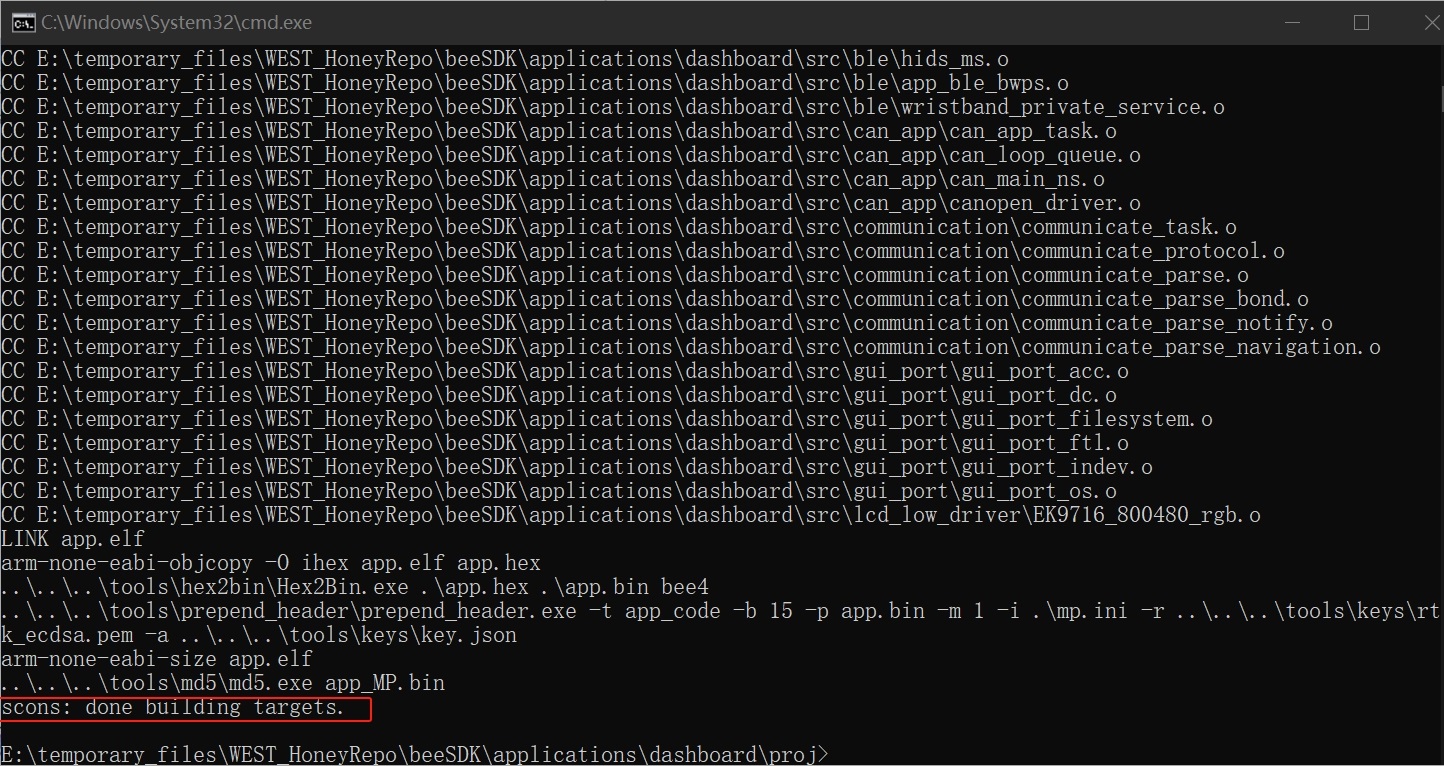
SCONS Success
Building and Downloading
Refer to Compilation and Download to build and download. It is worth noting that:
In the step Generating Flash Map, the developer need to generate the
flash_map.iniaccording to theSDK\applications\dashboard\proj\flash_map.h.-
In the step Generating System Config File, dashboard requires at least 2 slave links and the AE feature. Other features can be configured as required.
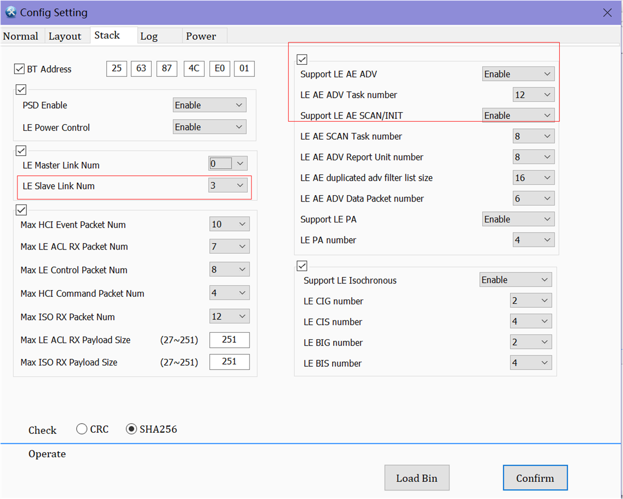
Dashboard Config File
Note
This chapter introduces the sample compilation method (such as Keil, gcc, etc.) and how to download it to the hardware board (Jlink, mptool, etc.).
-
In the step Generating App Image:
The path of dashboard SDK Keil project is
SDK\applications\dashboard\proj\mdk.-
Gcc Environment Setup Guide
Install python: go to the python official website to download the python installer suitable for the current system
Follow the installation instructions. Make sure to note the installation path of python, as you will need to add it to the system environment variables
Add the copied python installation path to both the system environment variables and the user environment variables, This ensures that Python can be recognized globally across the system
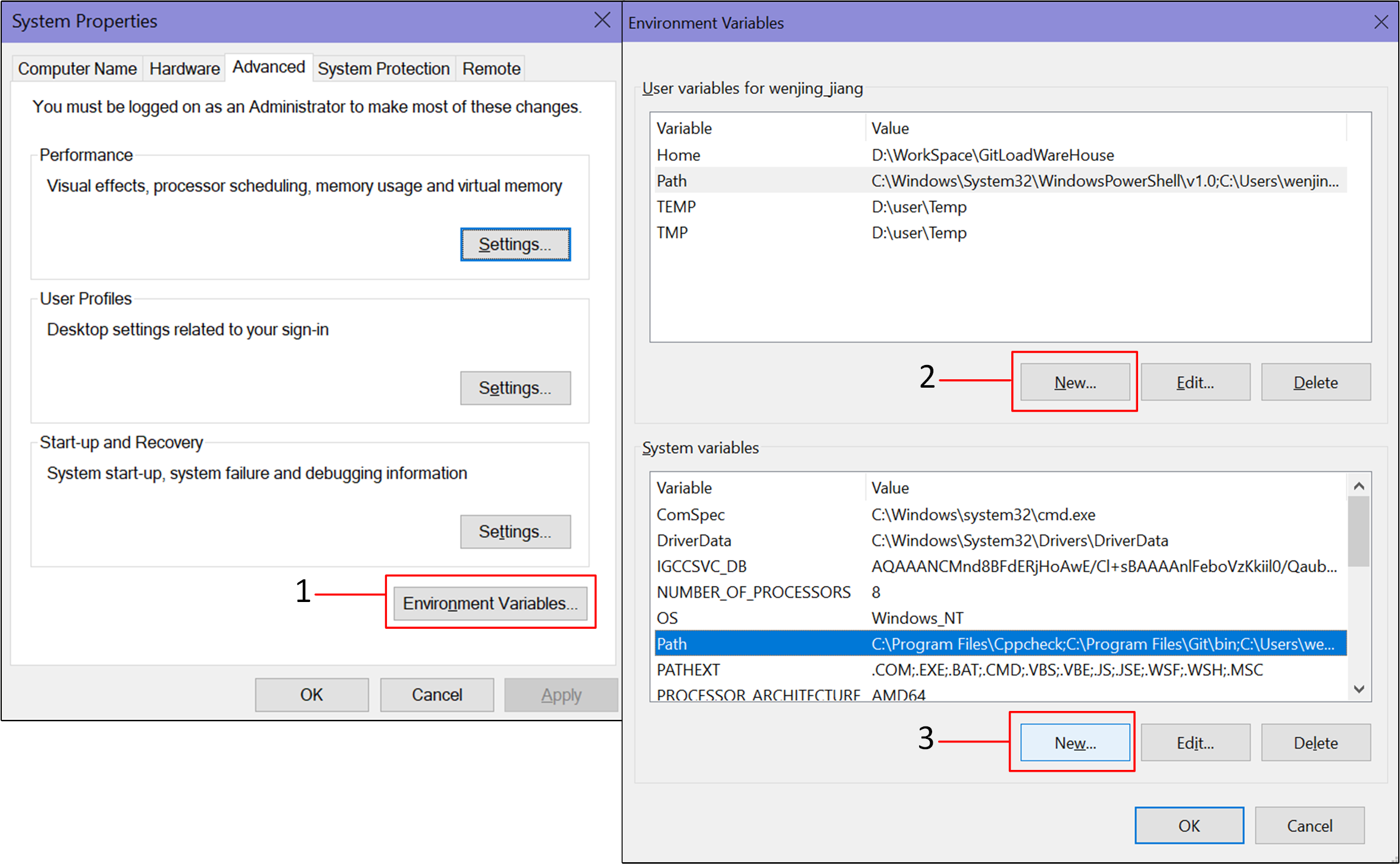
Python Path
Install Scons: open a command prompt window (enter commands in any file path cmd ),run the command pip install scons==4.4.0 to install the specified version of the scons library.
Cross-compiler installation: The recommended compiler version is 12.3.
Gcc compilation: In the Dashboard project path:
SDK\applications\dashboard\proj, use the console command line to run the command scons, which will automatically build the project and use gcc to complete the compilation. After the project is compiled using gcc, an App image will be generated in the default project path, where the burned file is a binary file with MD5 verification.
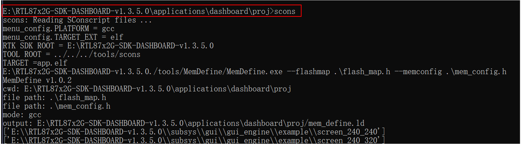
Dashboard Gcc Scons
Dashboard Gcc Scons Success
J-Link Download and Debug
J-Link is an emulator/debugger developed by SEGGER. It is a tool specifically for Arm processors that can be used to develop, debug, and test firmware for embedded devices. J-Link has high-speed and reliable simulation performance, supports real-time debugging and fast firmware downloading, and can help developers speed up the process of debugging and verifying embedded systems and improve development efficiency and quality.
J-Link supports multiple connection interfaces, such as JTAG, SWD, etc. Since SWD uses fewer wires, RTL8772GWP uses this interface: RTL87x2G-SWD Compatible Interface. In addition, J-Link is also compatible with multiple development environments and IDEs (such as Keil MDK, IAR Embedded Workbench, etc.). For Keil environment settings, please refer to Keil MDK.
It is recommended to use J-Link Software v6.44 (or later). For more information, see J-Link Download for compiling and debugging.
SWD Wiring
RTL8772GWP |
SWD |
|---|---|
RTL8772GWP |
SWD |
GND(black) |
GND |
P1_0(green) |
SWIO |
P1_1(yellow) |
SWCK |
VDEX(red) |
Vterf/3.3V |
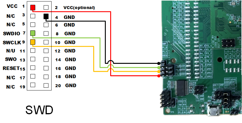
SWD Wiring
Keil Interface Settings
Refer to Keil MDK perform Keil interface settings.
Experimental Verification
After burning the sample program to EVB board, users can test whether the navigation information transmission, message pop-up window, etc. are normal by using the application development kit Dashboard.
EVB Debugging
To ensure that EVB can be used normally, users can follow the steps below:
Prepare an EVB, confirm that the EVB interface wiring is correct (UART-USB Wiring), put the EVB into download mode, and power on the EVB.
-
Double-click to run MPTool.exe , and refer to Bring Up EVB for specific operation steps and file paths.
At Load Layout, click .. to load
flash_map.inifile.Click Browse to load all burning files following files.
Click User Data to add user resource
root.bin.
The user data load address and size are automatically determined, but note that the address may overlap with the address specified in FlashMap. (In this example, the address is set to 0x04400000.)

User Data Interface
Click Detcet to successfully identify the COM port of EVB.
Click Open to successfully open the COM port.
Click Download to burn, and the progress bar shows the current burning progress.
The progress bar shows OK, indicating that the file is burned successfully.
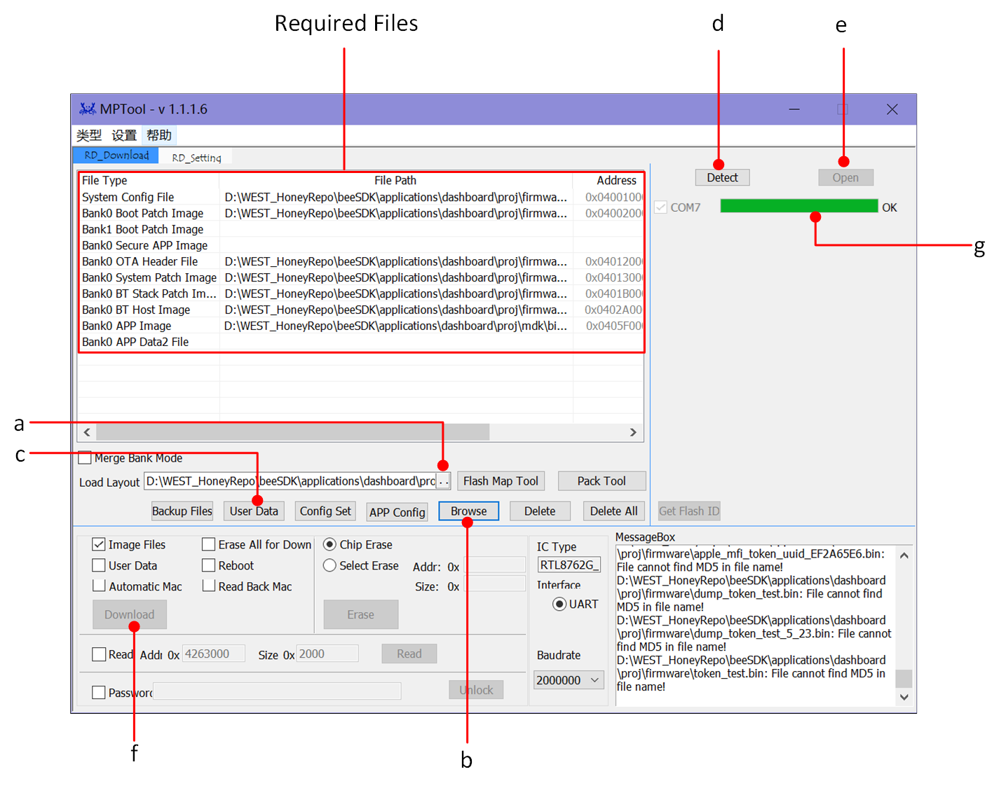
MPTool Burning Interface
-
After the program is burned, refer to Working Mode to put the EVB into working mode.
Observe the EVB behavior (search for BLE broadcast on the phone), or check whether the SoC-side Log is as expected.
For EVB hardware peripheral wiring, please refer to Wiring, and for program burning, please refer to Compilation and Download. After completing the above steps, short-circuit the Log and RX on the back of the EVB, press the Reset button on the EVB board or power on the EVB board again.
Users can use the following two methods to detect whether the SoC-side program is running normally:
sdk\tools), searches for and connects to the BLE signal, and the boot screen displays the status GUI Simulator Running Effect (one frame).Note
Broadcast name: BLE_DASHBOARD, Bluetooth address: [25:63:87:4C:E0:01]
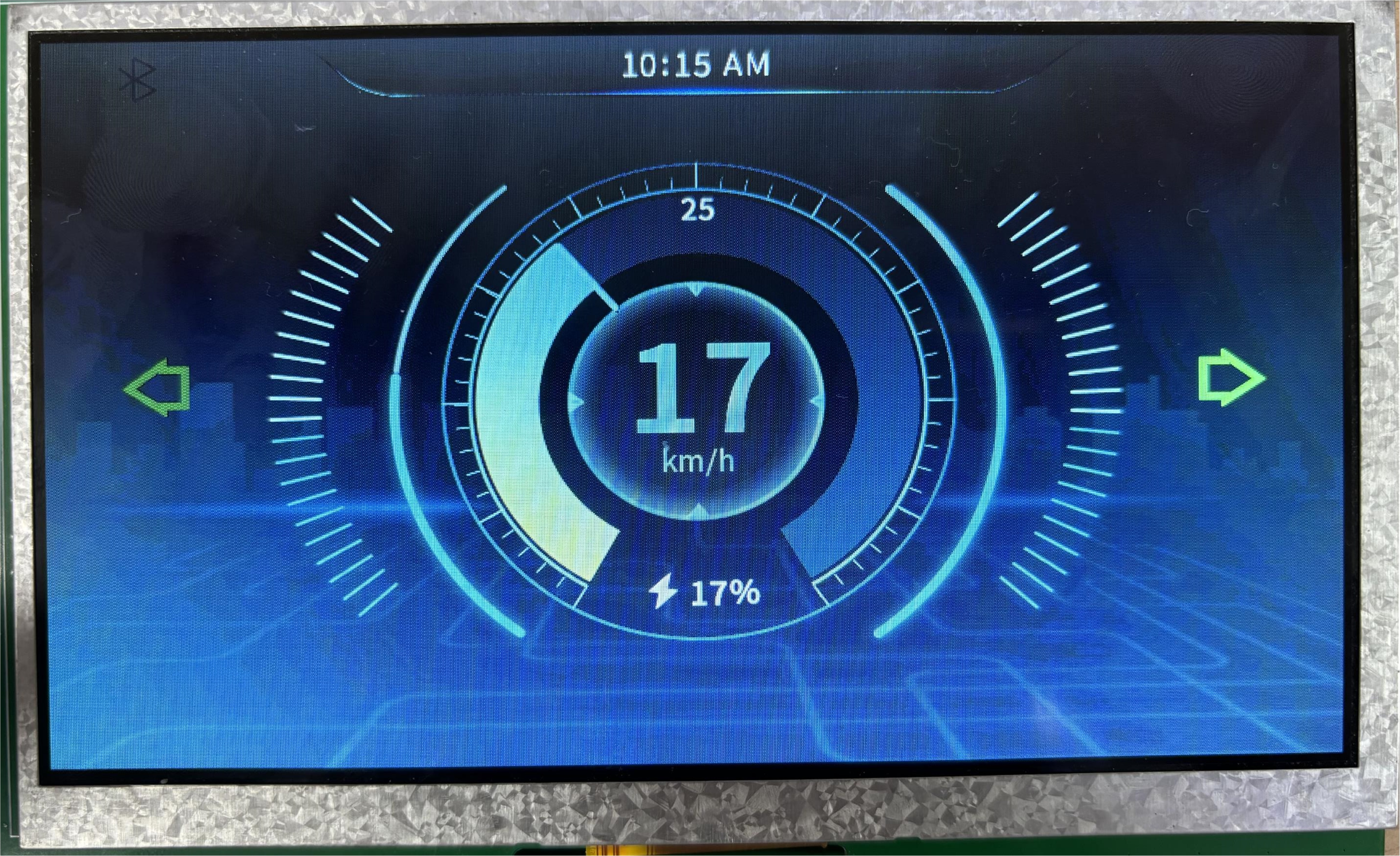
GUI Screen Display
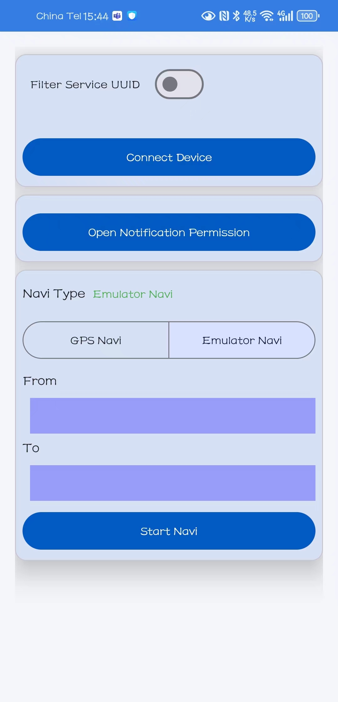
Dashboard APP Main Interface
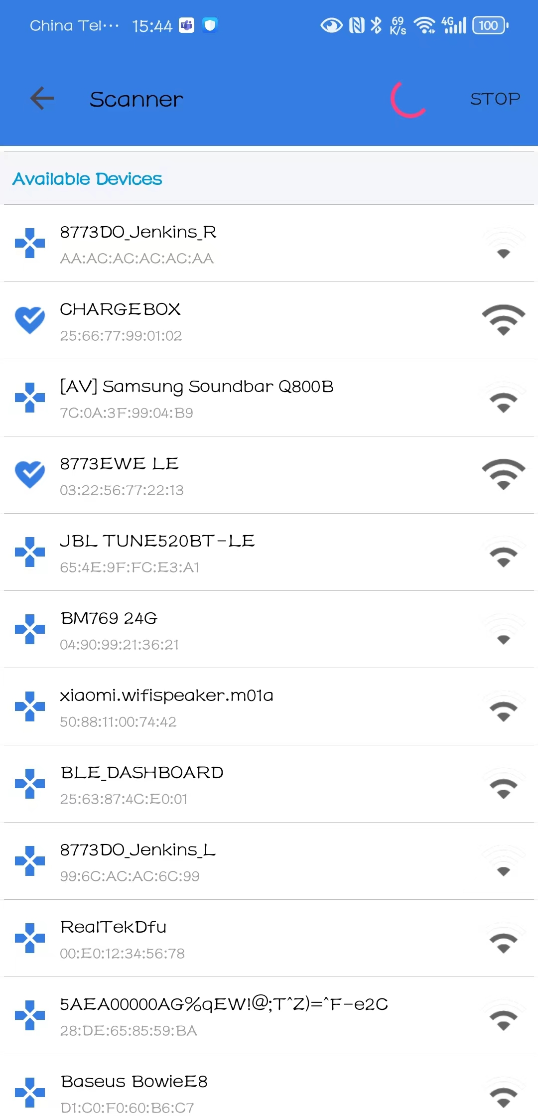
Dashboard APP Search Interface
Log Capture and Analysis
Please refer to Log Wiring for the Dashboard Navigation Interface EVB Board Wiring. After the EVB board is powered on, once the finish gui_mian Log appears, it means that the device interface initialization is complete and the screen refreshes normally. Click Connect Device on the mobile phone dashboard APK interface, and the Log prints GAP adv stoped:because connection created, which means that the mobile phone is successfully connected to the device.
If the user needs to modify the flash_map.h , he can refer to Flash Guide.
Software Design
This chapter mainly introduces the software-related technical parameters and behavioral specifications of the RTL8772GWP dashboard solution. It provides a software overview of all dashboard functions, which are used to guide dashboard development and track problems encountered in software testing.
Source Code Directory
Project directory:
sdk\application\dashboard\projSource code directory:
sdk\application\dashboard\src
Source files in dashboard application project are currently categorized into several groups as below.
└── Project: dashboard
    └── app                             includes app main
        ├── menu_config.h
        ├── main.c
        ├── dashboard_init.c
        ├── flash_map.h
        ├── board.h
        └── mem_config.h
    └── Device                          includes startup code
        ├── startup_rtl.c
        └── system_rtl.c
    ├── Lib                             includes all binary symbol files that user application is built on
    ├── Peripheral                      includes all peripheral drivers and module code used by the application
    └── Profile                         includes BLE profiles or services used by the find my application
        ├── ancs_client.c
        ├── gatt_client.c
        ├── bas.c
        ├── dis.c
        ├── dfu_service.c
        ├── ota_service.c
        └── tps.c                       tx power service
    └── dfu                             includes the dashboard dfu application implementation
        ├── dfu_common.c
        └── ble_dfu_transport.c
    └── dfu_task                        includes the  dashboard dfu task application implementation
        ├── dfu_main.c
        ├── dfu_task.c
        └── dfu_app.c
    ├── rtk_gui                         includes all gui port
    ├── realgui/3rd                     includes Third-party library
    ├── realgui/app                     includes Reallek gui app
    ├── realgui/dc                      includes Reallek gui app
    ├── realgui/engine                  includes all gui engine
    ├── realgui/demo                    includes all gui demo
    ├── realgui/input                   includes all gui input
    ├── realgui/misc                    includes all gui misc
    ├── realgui/widget                  includes all gui widget
    ├── database                        includes all database
    └── fs                              includes the  file system
        └──  romfs.c
    └── hal_drivers                     includes the  dashboard hardware layer driver
        ├── drv_flash.c
        ├── drv_dlps.c
        ├── drv_lcd.c
        └── drv_gpio.c
    └── lcd_low_driver                  includes the  dashboard hardware layer lcd driver
        └── EK9716_800480_rgb.c
    └── Compiler                        includes the  dashboard compiler
        ├── syscall.c
        └── syscall_mem.c
    └── bt_app                          includes the  dashboard bluetooth app
        ├── app_le_link_util.c
        ├── app_ble_bas.c
        ├── ancs.c
        ├── app_gap.c
        ├── app_task.c
        ├── his_ms.c
        ├── writband_private_service.c
        ├── app_ble_ota.c
        ├── app_ble_bwps.c
        └── app_ble_dfu.c
    └── communication                   includes all communication drivers and module code used by the application
Flash Layout
Application default flash layout header file: sdk\application\dashboard\proj\flash_map.h
Example Layout with a Total Flash Size of 1MB |
Size(Byte) |
Start Address |
|---|---|---|
Reserved |
4K |
0x04000000 |
OEM Header |
4K |
0x04001000 |
Bank0 Boot Patch |
32K |
0x04002000 |
Bank1 Boot Patch |
32K |
0x0400A000 |
OTA Bank0 |
1332K |
0x04012000 |
|
4K |
0x04012000 |
|
32K |
0x04013000 |
|
60K |
0x0401B000 |
|
212K |
0x0402A000 |
|
1008K |
0x0405F000 |
|
0K |
0x0415B000 |
|
0K |
0x0415B000 |
|
16K |
0x0415B000 |
|
0K |
0x0415F000 |
|
0K |
0x0415F000 |
|
0K |
0x0415F000 |
|
0K |
0x0415F000 |
OTA Bank1 |
0K |
0x040AC000 |
Bank0 Secure APP code |
16K |
0x0415F000 |
Bank0 Secure APP Data |
0K |
0x04163000 |
Bank1 Secure APP code |
0K |
0x04163000 |
Bank1 Secure APP Data |
0K |
0x04163000 |
OTA Temp |
1008K |
0x04163000 |
FTL |
16K |
0x0425F000 |
APP Defined Section1 |
8K |
0x04263000 |
APP Defined Section2 |
0K |
0x04265000 |
Important
To adjust flash layout, flow the steps listed on the Generating Flash Map in Quick Start.
After flash layout adjustment, you must flow the steps listed on the Generating OTA Header and Generating System Config File with new
flash_map.ini.
Software Architecture
The system software architecture is shown below:
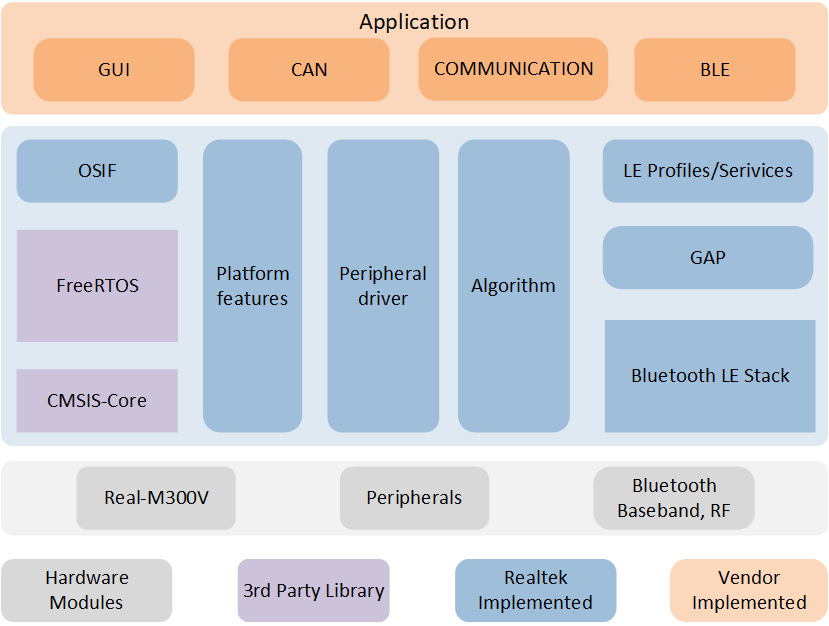
Software Architecture
IO Drivers: Provide application layer access to the interface of RTL87x2G peripherals.
OSIF: Abstraction layer for real-time operating systems.
GAP: Abstraction layer which user application communicates with BLE stack.
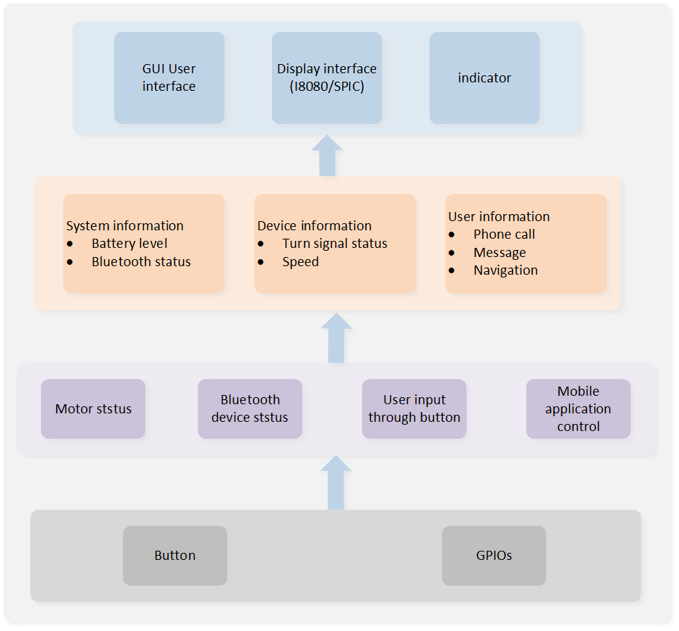
Dashboard Application System Diagram
/* Non-Secure main. */
int main(void)
{
    DBG_DIRECT("Non-Secure World: main");
    dashboard_system_clock_init();
    dashboard_components_init();
    dashboard_task_init();

    /* Start scheduler. */
    os_sched_start();
}
/*-----------------------------------------------------------*/
Tasks and Priorities
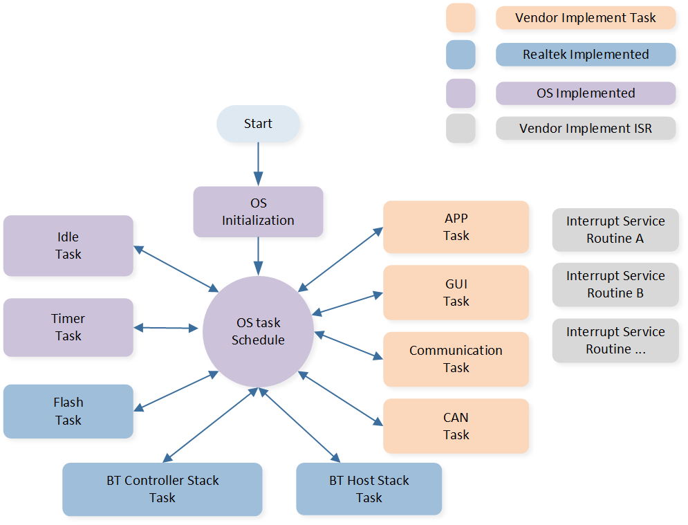
RTL8772GWP uses RTOS by default, and encapsulates a layer of OS if interface on this basis. RTL8772GWP has built-in Timer Task, Idle Task, Flash Task, BT Controller Stack Task, BT Host Stack Task, and the dashboard application has its own APP Task, GUI Task, Communication Task, and CAN Task.
Dashboard Application Task Composition
Task |
Describe |
Priority |
|
|---|---|---|---|
Timer |
implementing software timers required by FreeRTOS |
6 |
|
BT Controller Stack |
implement the bluetooth protocol stack below HCI |
6 |
|
BT Host Stack |
implement bluetooth protocol stack above HCI |
2 |
|
Flash |
handling asynchronous flash requests |
1 |
|
Idle |
run background tasks |
including DLPS |
0 |
App |
process different messages and events through message queues and event processing functions to manage and control bluetooth functions |
6 |
|
GUI |
processing image generation and screen data transmission |
1 |
|
Communication |
handling bluetooth interactive communications |
1 |
|
CAN |
handling CAN communication |
1 |
Note
Multiple application tasks can be created, and memory resources will be allocated accordingly.
Idle tasks and timer tasks are provided by FreeRTOS.
Tasks have been configured to be preemptive based on their priority using the SysTick interrupt.
Interrupt Service Routines (ISR) have been implemented by the vendor.
App task initialization related code entry:
void dashboard_task_init(void)
{
#if (RTK_BT_TASK == 1) || (RTK_BLE_TASK == 1)
    bt_task_init();
#endif
#ifdef ENABLE_RTK_GUI
#ifdef ENABLE_RTK_GUI_SCRIPT_AS_A_APP
    gui_server_init();
#else
    gui_main();
#endif
#endif
}
void dashboard_system_clock_init(void)
{
    uint32_t actual_mhz;
    int32_t ret0, ret1, ret2, ret3;
    ret0 = pm_cpu_freq_set(125, &actual_mhz);

    ret1 = flash_nor_set_seq_trans_enable(FLASH_NOR_IDX_SPIC0, 1);
    ret2 = fmc_flash_nor_clock_switch(FLASH_NOR_IDX_SPIC0, 160, &actual_mhz);
    ret3 = flash_nor_try_high_speed_mode(0, FLASH_NOR_DTR_4_BIT_MODE);

    APP_PRINT_INFO5("ret0 %d , ret1 %d , ret2 %d , ret3 %d actual_mhz %d", ret0, ret1, ret2, ret3,
                    actual_mhz);
    fmc_psram_clock_switch(PSRAM_IDX_SPIC1, 160, &actual_mhz);
    drv_dlps_exit_cbacks_register("psram", psram_winbond_opi_init);
    pm_display_freq_set(CLK_PLL1_SRC, 100, 100);
    DBG_DIRECT("finish dashboard_system_clock_init");
}
void dashboard_components_init(void)
{
#if (RTK_HAL_GPIO == 1)
    hw_pin_init();
#endif

#if (RTK_HAL_UART == 1)
    hw_uart_init();
#endif

#if (RTK_HAL_I2C == 1)
    hw_i2c_init();
#endif

#if (RTK_HAL_ADC == 1)
    hw_adc_init();
#endif

#if (RTK_HAL_LCD == 1)
    hw_lcd_init();
#endif

#if (RTK_HAL_TOUCH == 1)
    drv_touch_init();
#endif

#ifdef MODULE_VG_LITE
    hw_gpu_init();
#endif

#if (RTK_HAL_RTC == 1)
    hw_rtc_init();
#endif
#if (WS_USING_LETTER_SHELL == 1)
    userShellInit();
#endif
#ifdef RTK_PRIVATE_SERVICE
    communicate_task_init();
#endif // DEBUG

#if (RTK_HAL_DLPS == 1)
    pwr_mgr_init();
#endif
}
APP Task
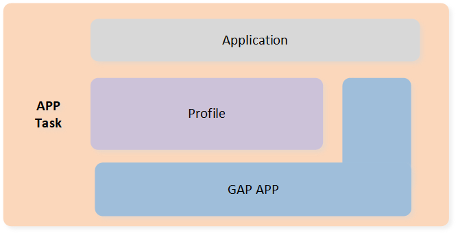
APP Task Architecture
The BLE related status is handled by
gap_handle_msgto process the messages sent by the upper layer, and the BLE data sending and receiving callbacks are registered to the read/write interface registered when the app creates the service.The user application layer freely implements the control of BLE behavior, including broadcast switch, establishing connection, updating connection parameters, etc.
-
New app task: The structure of
app_dashboard_launcherdisplays two basic elements:thread_detryandui_design.The
ui_designfunction creates the UI interface and required system resources.Developers can place programs that execute periodically in the
thread_entryor message entry to receive messages from other tasks.
  gui_app_t app_dashboard_launcher =
  {
      .screen =
      {
          .name = "app_dashboard_launcher",
          .x    = 0,
          .y    = 0,
      },
      .thread_entry = app_dashboard_launcher_update_thread,
      .ui_design = app_dashboard_launcher_ui_design,
  };

  gui_app_t *get_app_dashboard_launcher(void)
  {
      return &app_dashboard_launcher;
}
GUI Task
GUI refresh is triggered by keystrokes, timers, and other application behaviors. Before the interface is refreshed, the user updates the information of each control in the interface according to the current behavior. The core part of the GUI is drawn in the frame buffer according to the type and position of each control. The frame buffer can be internal RAM or PSRAM. In order to save RAM resources, a whole frame of FrameBuffer is divided into multiple parts (10 lines are used as a block in the current SDK, and a total of 48 blocks are drawn), and the segments are drawn and sent to the screen synchronously through LCDC. When using PSRAM, each part is first updated to the whole frame PSRAM, and then the whole frame is sent directly to the screen through DPI.
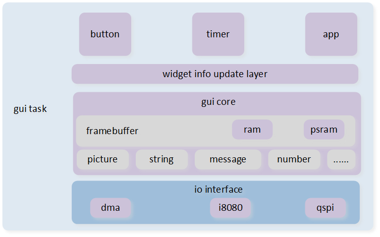
GUI Task Architecture
The screen resolution in the demo application is 800*480. We will create two Window widgets as basic containers to display information in the BLE connected and unconnected states. The functions app_dashboard_create_main_display() and app_dashboard_create_connected_display() will create the remaining widgets and attach them to the two window widgets respectively.
Dashboard API Description Dashboard API Interface
Description
app_dashboard_launcher_ui_design ()main entrance of UI interface
app_dashboard_create_main_display ()display dashboard home page information
app_dashboard_data_get_show_main_display ()get dashboard home page information
app_dashboard_create_connected_display ()display navigation page information
app_dashboard_initialize_data ()initialize control content
app_update_gui_widget ()update control content
app_dashboard_get_data ()get dashboard information
app_dashboard_data_set_battery_level ()set the latest battery data
app_dashboard_data_get_battery_level ()get current battery data
app_dashboard_data_set_car_speed ()set the current car speed
app_dashboard_data_get_car_speed ()get the current car speed
app_dashboard_data_set_car_turn_info ()set the current car turning information
app_dashboard_data_get_car_turn_info ()get the current car turning information
app_dashboard_data_set_bluetooth_status ()set the current Bluetooth status
app_dashboard_data_get_bluetooth_status ()get the current Bluetooth status
app_dashboard_data_set_navi_status ()set the current navigation status
app_dashboard_data_get_navi_status ()get the current navigation status
app_dashboard_data_update_navi_status ()update the current navigation status
app_dashboard_data_set_phone_status ()set the current phone status
app_dashboard_data_get_phone_status ()get the current phone status
app_dashboard_data_update_phone_status ()set the current phone information
app_dashboard_data_set_message_data_update ()set the current message information
app_dashboard_data_get_message_data_update ()get the current message information
app_dashboard_data_update_message_status ()update the current message information
app_dashboard_data_set_current_timer ()set the current time information
app_dashboard_data_get_current_timer ()get the current time information
app_dashboard_data_set_tense_timer_info ()set the current tense information
app_dashboard_data_get_tense_timer_info ()get the current tense information
app_dashboard_data_set_reject_end_call ()set the rejection and hang up the phone
app_dashboard_data_set_accept_call ()set the answer phone
app_dashboard_update_main_display_speed_info ()update the main interface speed information
app_dashboard_update_main_display_turn_info ()update the main interface turn information
app_dashboard_update_main_display_bluetooth_info()update the Bluetooth connection information on the main interface
app_dashboard_update_main_display_phone_infor()update the phone information on the main interface
app_dashboard_update_main_display_message_infor()update the message information on the main interface
GUI Control Description GUI Control
Description
gui_win_create()create win window
gui_set_font_mem_resourse()find and set font resources in memory
gui_win_set_animate()set window animation effect
gui_img_set_attribute()set the attributes of image object
gui_img_create_from_mem()create image object
gui_text_create()create text object
gui_text_mode_set()set the text mode of text object
For more details about GUI controls, please refer to the documentation: https://docs.realmcu.com/Honeygui/en/latest/widgets/index.html
    void app_dashboard_launcher_ui_design(gui_app_t *app)
    {
        win_connected_display = gui_win_create(&(app->screen),
                                "win_connected_display", 0, 0, 800, 480);
        win_main_display = gui_win_create(&(app->screen), "win_main_display", 0, 0, 800, 480);
        gui_font_mem_init(HARMONYOS_SIZE28_BITS1_FONT_BIN);
        gui_font_mem_init(HARMONYOS_SIZE32_BITS1_FONT_BIN);
        gui_font_mem_init(HARMONYOS_SIZE56_BITS1_FONT_BIN);

        app_dashboard_create_main_display(win_main_display);
        app_dashboard_create_connected_display(win_connected_display);
        win_main_display->base.not_show = false;
        win_connected_display->base.not_show = true;
        app_dashboard_initialize_data();
}
-
Create a BLE non-connected widget
The
app_dashboard_create_main_displayfunction will rely on the layout file BLE Non-Connected State Layout to assign the widgets to the correct coordinates. We will register two eventsobj_animateto handle the state of the panel before and after refresh. At the end of this function, we will call the refresh function of each widget to display the latest information to the user.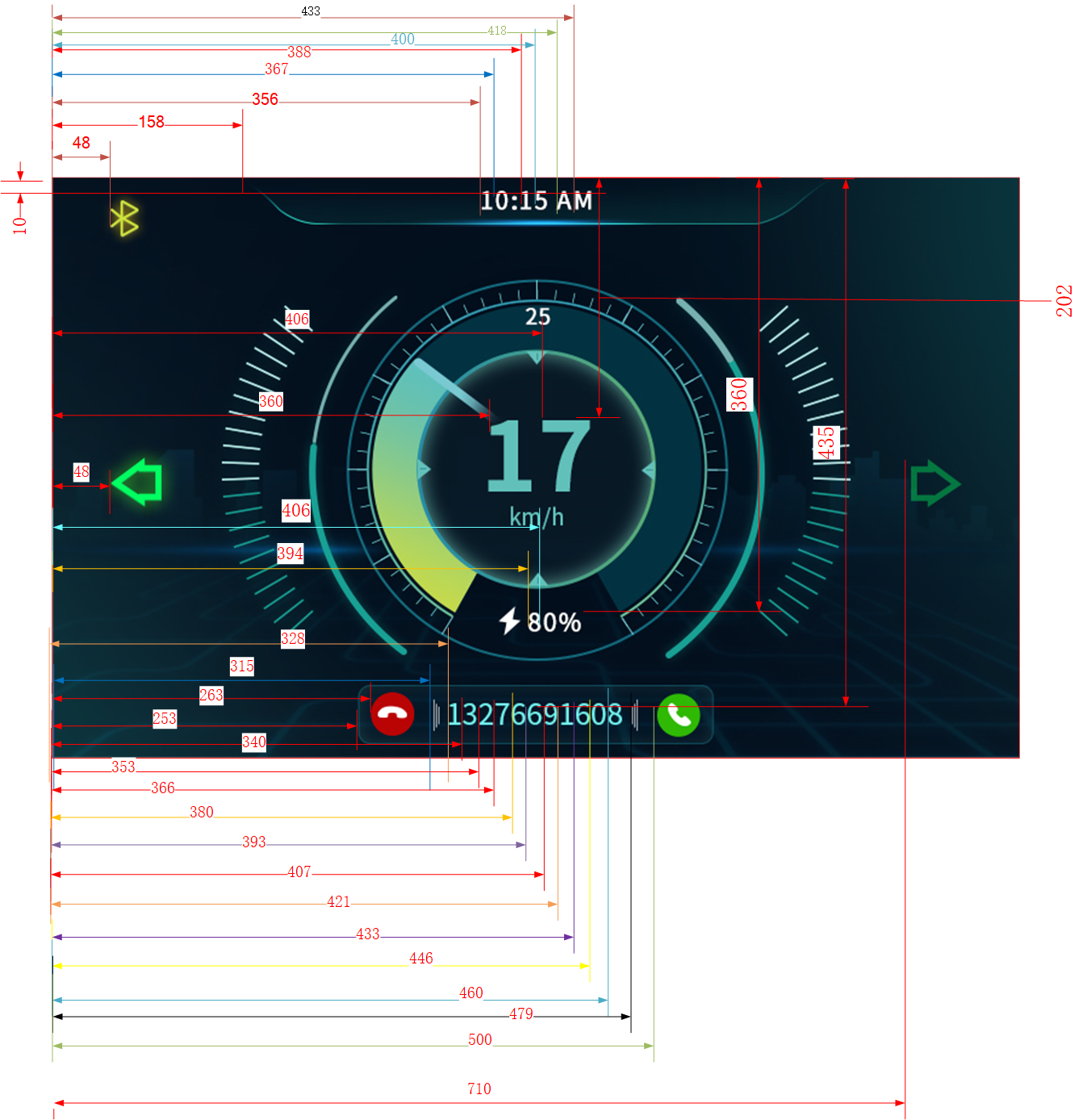
BLE Non-Connected State Layout
void app_dashboard_create_main_display(gui_win_t *target_main_display) { /* set update callback */ gui_win_set_animate(target_main_display, 1000, -1, paint_main_display_cb, target_main_display); /* set Image data */ dashboard_background = gui_img_create_from_mem(target_main_display, "dashboard_background", BACKGROUND_BIN, 0, 0, 800, 480); speed_high_digital = gui_img_create_from_mem(target_main_display, "speed_high_digital", SPED0_BIN, 360, 202, 40, 60); speed_low_digital = gui_img_create_from_mem(target_main_display, "speed_low_digital", SPED0_BIN, 406, 202, 40, 60); bluetooth_status = gui_img_create_from_mem(target_main_display, "bluetooth_status", BTOF_BIN, 48, 10, 23, 30); left_turn_light_status = gui_img_create_from_mem(target_main_display, "left_turn_light_status", TL_OF_BIN, 48, 208, 42, 40); right_turn_light_status = gui_img_create_from_mem(target_main_display, "right_turn_light_status", TR_OF_BIN, 710, 208, 42, 40); hour_high_digital = gui_img_create_from_mem(target_main_display, "hour_high_digital", TIMER0_BIN, 355, 12, 9, 16); hour_low_digital = gui_img_create_from_mem(target_main_display, "hour_low_digital", TIMER0_BIN, 366, 12, 9, 16); min_high_digital = gui_img_create_from_mem(target_main_display, "min_high_digital", TIMER0_BIN, 387, 12, 9, 18); min_low_digital = gui_img_create_from_mem(target_main_display, "min_low_digital", TIMER0_BIN, 399, 12, 9, 18); tense_high_digital = gui_img_create_from_mem(target_main_display, "tense_high_digital", APM_A_BIN, 417, 12, 9, 18); tense_low_digital = gui_img_create_from_mem(target_main_display, "tense_low_digital", APM_M_BIN, 432, 12, 9, 18); bat_high_digital = gui_img_create_from_mem(target_main_display, "bat_high_digital", TIMER0_BIN, 394, 360, 9, 18); bat_low_digital = gui_img_create_from_mem(target_main_display, "bat_low_digital", TIMER0_BIN, 406, 360, 9, 18); tel_box = gui_img_create_from_mem(target_main_display, "tel_box", TELBOX_BIN, 253, 410, 295, 49); tel_accept = gui_img_create_from_mem(target_main_display, "tel_accept", TELBOX_BIN, 253, 410, 295, 49); tel_reject_end = gui_img_create_from_mem(target_main_display, "tel_reject_end", TELBOX_BIN, 253, 410, 295, 49); refuse_button = gui_img_create_from_mem(target_main_display, "refuse_button", REFUS_BIN, 263, 416, 36, 36); ans_button = gui_img_create_from_mem(target_main_display, "ans_button", ANS_BIN, 500, 416, 36, 36); tel_box_left_button = gui_img_create_from_mem(target_main_display, "tel_box_left_button", SYMB1_BIN, 315, 416, 36, 36); tel_box_right_button = gui_img_create_from_mem(target_main_display, "tel_box_right_button", SYMB2_BIN, 479, 416, 36, 36); dashboard_pointer = gui_img_create_from_mem(target_main_display, "dashboard_Cpointer", DASHBOARD_0_BIN, 243, 84, 0, 0); short_message = gui_img_create_from_mem(target_main_display, "short_message", MESSAGE_BIN, 221, 0, 359, 80); /* set font data */ app_phone_data current_phone_status; app_dashboard_data_get_phone_status(¤t_phone_status); short_tel_number = gui_text_create(target_main_display, "short_tel_number", 322, 415, 158, 30); memcpy(&show_tel_number[0], ¤t_phone_status.current_phone_number[0], current_phone_status.current_phone_number_len); gui_text_set(short_tel_number, (char *)show_tel_number, GUI_FONT_SRC_BMP, gui_rgb(UINT8_MAX, UINT8_MAX, UINT8_MAX), current_phone_status.current_phone_number_len, 28); gui_text_mode_set(short_tel_number, CENTER); short_tel_accept = gui_text_create(target_main_display, "short_tel_accept", 360, 415, 800, 30); gui_text_set(short_tel_accept, "calling", GUI_FONT_SRC_BMP, gui_rgb(UINT8_MAX, UINT8_MAX, UINT8_MAX), 7, 32); app_message_data current_message_status; app_dashboard_data_get_message_data_update(¤t_message_status); memcpy(&show_message_data[0], ¤t_message_status.wechat_msg[0], current_message_status.wechat_msg_len); short_message_data = gui_text_create(target_main_display, "short_message_data", 300, 10, 240, 50); gui_text_set(short_message_data, (char *)show_message_data, GUI_FONT_SRC_BMP, gui_rgb(UINT8_MAX, UINT8_MAX, UINT8_MAX), (current_message_status.wechat_msg_len - 1), 32); gui_text_mode_set(short_message_data, MULTI_LEFT); /* Prepare the intial data */ app_dashboard_update_main_display_time_info(); app_dashboard_update_main_display_tense_apm_info(app_dashboard_data_get_tense_timer_info()); app_dashboard_update_main_display_battery_info(app_dashboard_data_get_battery_level()); app_dashboard_update_main_display_speed_info(app_dashboard_data_get_car_speed()); app_dashboard_update_main_display_turn_info(app_dashboard_data_get_car_turn_info()); app_dashboard_update_main_display_bluetooth_info(app_dashboard_data_get_bluetooth_status()); app_dashboard_update_main_display_phone_infor(¤t_phone_status); app_dashboard_update_main_display_message_infor(¤t_message_status); }
BLE connection status layout
void app_dashboard_create_connected_display(gui_win_t *target_connected_display) { /* set update callback */ gui_win_set_animate(target_connected_display, 1000, -1, paint_connected_display_cb, target_connected_display); /* set Image data */ dashboard_c_background = gui_img_create_from_mem(target_connected_display, "dashboard_c_background", BACKGROUND_C_BIN, 0, 0, 800, 480); speed_high_c_digital = gui_img_create_from_mem(target_connected_display, "speed_high_c_digital", SPED_C0_BIN, 214, 232, 27, 40); speed_low_c_digital = gui_img_create_from_mem(target_connected_display, "speed_low_c_digital", SPED_C0_BIN, 251, 232, 27, 40); hour_high_c_digital = gui_img_create_from_mem(target_connected_display, "hour_high_digital", TIMER0_BIN, 355, 12, 9, 16); hour_low_c_digital = gui_img_create_from_mem(target_connected_display, "hour_low_digital", TIMER0_BIN, 366, 12, 9, 16); min_high_c_digital = gui_img_create_from_mem(target_connected_display, "min_high_digital", TIMER0_BIN, 387, 12, 9, 18); min_low_c_digital = gui_img_create_from_mem(target_connected_display, "min_low_digital", TIMER0_BIN, 399, 12, 9, 18); tense_high_c_digital = gui_img_create_from_mem(target_connected_display, "tense_high_c_digital", APM_CA_BIN, 417, 12, 9, 18); tense_low_c_digital = gui_img_create_from_mem(target_connected_display, "tense_low_c_digital", APM_CM_BIN, 432, 12, 9, 18); bat_high_c_digital = gui_img_create_from_mem(target_connected_display, "bat_high_c_digital", TIMER0_BIN, 238, 371, 9, 18); bat_low_c_digital = gui_img_create_from_mem(target_connected_display, "bat_low_c_digital", TIMER0_BIN, 250, 371, 9, 18); left_turn_light_c_status = gui_img_create_from_mem(target_connected_display, "left_turn_light_c_status", TL_OF_C_BIN, 110, 10, 42, 40); right_turn_light_c_status = gui_img_create_from_mem(target_connected_display, "right_turn_light_c_status", TR_OF_C_BIN, 665, 10, 42, 40); navi_c_status = gui_img_create_from_mem(target_connected_display, "navi_c_status", NAVI_C1_BIN, 505, 170, 268, 218); refuse_c_button = gui_img_create_from_mem(target_connected_display, "refuse_c_button", REFUS_BIN, 502, 410, 36, 36); ans_c_button = gui_img_create_from_mem(target_connected_display, "ans_c_button", ANS_BIN, 740, 410, 36, 36); tel_box_left_c_button = gui_img_create_from_mem(target_connected_display, "tel_box_left_c_button", SYMB1_BIN, 554, 414, 36, 36); tel_box_right_c_button = gui_img_create_from_mem(target_connected_display, "tel_box_right_c_button", SYMB2_BIN, 718, 414, 36, 36); dashboard_Cpointer = gui_img_create_from_mem(target_connected_display, "dashboard_Cpointer", DASHBOARD_C2_BIN, 110, 133, 9, 18); short_c_message = gui_img_create_from_mem(target_connected_display, "short_c_message", MESSAGE_BIN, 221, 0, 359, 80); /* set font data */ app_navi_data current_navi_data; app_dashboard_data_get_navi_data_update(¤t_navi_data); memcpy(&show_c_navigation_msg[0], ¤t_navi_data.navigation_msg[0], current_navi_data.navigation_num_len); short_c_navi_message_1 = gui_text_create(target_connected_display, "short_c_navi_message_1", 490, 88, 150, 60); gui_text_set(short_c_navi_message_1, (char *)show_c_navigation_msg, GUI_FONT_SRC_BMP, gui_rgb(UINT8_MAX, UINT8_MAX, UINT8_MAX), current_navi_data.navigation_num_len, 56); gui_text_mode_set(short_c_navi_message_1, RIGHT); memcpy(&show_c_navigation_unit[0], ¤t_navi_data.navigation_unit[0], current_navi_data.navigation_unit_len); short_c_navi_message_3 = gui_text_create(target_connected_display, "short_c_navi_message_3", 640, 108, 150, 40); gui_text_set(short_c_navi_message_3, (char *)show_c_navigation_unit, GUI_FONT_SRC_BMP, gui_rgb(0xcc, 0xcc, 0xcc), current_navi_data.navigation_unit_len, 32); gui_text_mode_set(short_c_navi_message_3, LEFT); memcpy(&show_c_road_names[0], ¤t_navi_data.road_names[0], current_navi_data.road_num_len); short_c_navi_message_2 = gui_text_create(target_connected_display, "short_c_navi_message_2", 490, 148, 300, 40); gui_text_set(short_c_navi_message_2, (char *)show_c_road_names, GUI_FONT_SRC_BMP, gui_rgb(0xcc, 0xcc, 0xcc), current_navi_data.road_num_len, 32); gui_text_mode_set(short_c_navi_message_2, CENTER); app_phone_data current_phone_status; app_dashboard_data_get_phone_status(¤t_phone_status); short_c_tel_number = gui_text_create(target_connected_display, "short_c_tel_number", 560, 410, 158, 30); memcpy(&show_c_tel_number[0], ¤t_phone_status.current_phone_number[0], current_phone_status.current_phone_number_len); gui_text_set(short_c_tel_number, (char *)show_c_tel_number, GUI_FONT_SRC_BMP, gui_rgb(UINT8_MAX, UINT8_MAX, UINT8_MAX), current_phone_status.current_phone_number_len, 28); gui_text_mode_set(short_c_tel_number, CENTER); short_c_tel_accept = gui_text_create(target_connected_display, "short_c_tel_accept", 600, 410, 800, 30); gui_text_set(short_c_tel_accept, "calling", GUI_FONT_SRC_BMP, gui_rgb(UINT8_MAX, UINT8_MAX, UINT8_MAX), 7, 28); app_message_data current_message_status; app_dashboard_data_get_message_data_update(¤t_message_status); memcpy(&show_c_message_data[0], ¤t_message_status.wechat_msg[0], current_message_status.wechat_msg_len); short_c_message_data = gui_text_create(target_connected_display, "short_c_message_data", 300, 10, 240, 50); gui_text_set(short_c_message_data, (char *)show_c_message_data, GUI_FONT_SRC_BMP, gui_rgb(UINT8_MAX, UINT8_MAX, UINT8_MAX), (current_message_status.wechat_msg_len - 1), 32); gui_text_mode_set(short_c_message_data, MULTI_LEFT); /* Prepare the intial data */ app_dashboard_update_connected_display_time_info(); app_dashboard_update_connected_display_tense_apm_info(app_dashboard_data_get_tense_timer_info()); app_dashboard_update_connected_display_battery_info(app_dashboard_data_get_battery_level()); app_dashboard_update_connected_display_speed_info(app_dashboard_data_get_car_speed()); app_dashboard_update_connected_display_turn_info(app_dashboard_data_get_car_turn_info()); app_dashboard_update_connected_display_phone_infor(¤t_phone_status); app_dashboard_update_connected_display_message_infor(¤t_message_status); }
BLE Communication Task
The communication task is responsible for the management of BLE data transmission, packaging the data according to the current transmission data command format and sending it through the Bluetooth protocol stack. Customers generally use their own Bluetooth data interaction format. Tasks can be used as a reference for sending methods or they can be implemented by themselves. Developers must refer to Bluetooth to familiarize themselves with the BLE service structure and how to process messages. In this design document, we will use the specified BLE service of the dashboard application as a demonstration. Developers can choose which BLE services to use in the mobile application according to their product requirements.
Dashboard Communication Block Diagram
After the mobile APP successfully connects to the dashboard device, the APP can transmit necessary information to the device using BLE write requests. All messages will be written via characteristics.
    /**      * @brief write characteristic data from stack. *
* @param ServiceId ServiceId generated when register to BT Host stack.
* @param iAttribIndex Attribute index of getting characteristic data.
* @param wLength length of data to be written.
* @param pValue pointer of data to be written.
* @return TProfileResult profile procedure results.         */
    T_APP_RESULT bwps_service_attr_write_cb(uint8_t conn_id, T_SERVER_ID service_id,
     uint16_t attrib_index, T_WRITE_TYPE write_type, uint16_t length, uint8_t *p_value,
                                            P_FUN_WRITE_IND_POST_PROC *p_write_ind_post_proc)
    {
        T_APP_RESULT  wCause  = APP_RESULT_SUCCESS;
        uint8_t *buf = NULL;
        APP_PRINT_INFO2("bwps_service_attr_write_cb: attrib_index = %d, data %b", attrib_index,
    CE_BINARY(length, p_value));

        if (p_value == NULL)
        {
            APP_PRINT_ERROR0("bwps_service_attr_write_cb, p_value is NULL");
            wCause = APP_RESULT_INVALID_VALUE_SIZE;
            return wCause;
        }

        switch (attrib_index)
        {
        default:
            wCause = APP_RESULT_ATTR_NOT_FOUND;
            APP_PRINT_ERROR2("bwps_service_attr_write_cb Error: attrib_index 0x%x, length %d", attrib_index,  length);
            break;
        case GATT_SRV_BWPS_TX_INDEX:
            APP_PRINT_INFO0("bwps_service_attr_write_cb, GATT_SRV_BWPS_TX_INDEX");
            /* copy gatt write value in tx_buffer, the first byte is value length*/
    #if 1
            buf = malloc((length + 1) * sizeof(uint8_t));
            buf[0] = length;
            memcpy(buf + 1, p_value, length);
            extern void *raw_data_receive_queue_handle;
            if (os_msg_send(raw_data_receive_queue_handle, &buf, 0) == false)
            {
                APP_PRINT_ERROR0("send_msg_to_l1send_task_fail");
                free(buf);
            }
    #endif
            break;
        case GATT_SRV_BWPS_DEVNAME_INDEX:
            APP_PRINT_INFO0("BWPS: update device name\n");
            break;
        }

        return wCause;
}
All received messages will be published to the raw_data_receive_queue_handle queue, which will be processed in the resolve_remote_data.
void l1receive_task(void *pvParameters)
{
    uint8_t *buf = NULL;
    os_alloc_secure_ctx(1024);
    os_msg_queue_create(&raw_data_receive_queue_handle, "rec_raw_data", 0x10, sizeof(void *));

    while (true)
    {
        if (os_msg_recv(raw_data_receive_queue_handle, &buf, 0xFFFFFFFF) == true)
        {
            //rt_kprintf("buf2 = 0x%x \n", buf);
            resolve_remote_data(buf + 1, buf[0]);
            free(buf);
        }
    }
}
Once the received data passes the data integrity check, the L2_frame_resolve will process the request. In the dashboard application, developers only need to process three types of data:
NAVIGATION_INFORMATION_ID
NOTIFY_COMMAND_ID
CONTROL_COMMAND_IDbool L2_frame_resolve(uint8_t *pData, uint16_t length) { if ((pData == NULL) || (length == 0)) { return false; } WRISTBAND_COMMUNICATE_COMMAND command_id = (WRISTBAND_COMMUNICATE_ COMMAND)pData[0]; uint8_t first_key = pData[2]; uint16_t first_value_length = (((pData[3] << 8) | pData[4]) & 0x1FF); APP_PRINT_INFO1("L2_frame_resolve length is %d", length); switch (command_id) { case NAVIGATION_INFORMATION_ID: { APP_PRINT_INFO1("NAVIGATION_INFORMATION_ID, KEY = 0x%x", first_key); APP_PRINT_INFO1("NAVIGATION_INFORMATION_ID,length is %d", length); APP_PRINT_INFO1("RECEIVE navi info is %b", TRACE_BINARY(length, (uint8_t *)pData + L2_FIRST_VALUE_POS)); resolve_Navigation_command(first_key, pData + L2_FIRST_VALUE_POS, first_value_length); } break; case NOTIFY_COMMAND_ID: { APP_PRINT_INFO2("NOTIFY_COMMAND_ID, KEY = 0x%x, info= 0x%x", first_key, pData[5]); resolve_Notify_command(first_key, pData + L2_FIRST_VALUE_POS, first_value_length, pData[5]); } break; case CONTROL_COMMAND_ID: { APP_PRINT_INFO1("CONTROL_COMMAND, KEY = 0x%x", first_key); resolve_Control_command(first_key, pData + L2_FIRST_VALUE_POS, first_value_length); } break; default: break; } return true; }
Whenever BLE receives a message from the mobile APP, it will update the data to the dashboard data container, and then the UI update thread will get the latest information and refresh the display.
CAN Communication Task
The CAN sample implements a basic CAN application task structure to manage and process CAN communication through tasks and message queues.
CAN API Description
Dashboard CAN Interface |
Description |
|---|---|
|
initializes the CAN application task and creates the task |
|
sends a message to the CAN task |
|
entry function for the CAN application task, creates message queues and continuously receives and processes events |
|
displays navigation page information |
|
initializes all tasks and drivers related to CAN |
|
initializes CANOpen tasks and message queues |
|
sends CAN data, including writing data to the send queue and handling write failures |
|
configures the CAN receive message buffer |
|
initializes CAN receive DMA to receive CAN messages via DMA |
|
transmits process data objects (PDO) over CAN |
|
CAN interrupt handler that manages various CAN interrupt events such as receive complete interrupts, send complete interrupts, and error interrupts |
Pin Definitions
#define CAN_TX_PIN          P1_4
#define CAN_RX_PIN          P1_6
CAN Send Task
    /**
* @brief  Send CAN data.
* @param  notused: The parameter is not used.
* @param  p_data: The message data.
* @note   API from CANFestival
* @return None
*/
unsigned char canSend(CAN_PORT notused, Message *p_data)
{
    static CAN_TxMsgDef CO_TxMsg;
    CO_TxMsg.CO_TxFrame.frame_brs_bit = CAN_BRS_NO_SWITCH_BIT_TIMING;
    CO_TxMsg.CO_TxFrame.standard_frame_id = p_data->cob_id;
    CO_TxMsg.CO_TxFrame.extend_frame_id = 0x00;
    CO_TxMsg.CO_TxFrame.frame_type = CAN_CheckFrameType(p_data->rtr, CAN_IDE_STANDARD_FORMAT,
                                                        CAN_EDL_STARDARD_FRAME);
    CO_TxMsg.CO_TxFrame.auto_reply_bit = RESET;
    CO_TxMsg.dlc = p_data->len;
    APP_PRINT_INFO2("[canSend] dlc = %d, std id = 0x%X", CO_TxMsg.dlc,
                    CO_TxMsg.CO_TxFrame.standard_frame_id);
    for (uint8_t i = 0; i < CO_TxMsg.dlc; i++)
    {
        CO_TxMsg.data[i] = p_data->data[i];
        APP_PRINT_INFO2("[canSend] CO_TxMsg.data[%d] = 0x%X", i, CO_TxMsg.data[i]);
    }
    if (!loop_queue_is_full(p_canSend_queue, sizeof(CAN_TxMsgDef)))
    {
        if (false == loop_queue_write_buf(p_canSend_queue, &CO_TxMsg,
                                        sizeof(CAN_TxMsgDef), true))
        {
            T_IO_MSG io_can_msg;
            io_can_msg.type = IO_MSG_TYPE_CAN_SEND;
            app_send_msg_to_cantask(&io_can_msg);
        }
        else
        {
            APP_PRINT_ERROR0("Write TxMsg failed!");
            return 0xFF;
        }
    }
    return 0;
}
CAN Receive Task
/**
* @brief  basic configuration of CAN rx message buffer.
* @param  None
* @return None
*/
void can_basic_rx(uint8_t MsgBuf_index)
{
    /* set CAN Rx message buffer */
    CANError_TypeDef rx_error;
    CANRxFrame_TypeDef rx_frame_type;
    rx_frame_type.msg_buf_id = MsgBuf_index;
    rx_frame_type.frame_rtr_mask = SET;
    rx_frame_type.frame_ide_mask = SET;
    rx_frame_type.frame_id_mask = CAN_FRAME_ID_MASK_MAX_VALUE;
#if CAN_RX_DMA_EN
    rx_frame_type.rx_dma_en = SET;
#else
    rx_frame_type.rx_dma_en = RESET;
#endif
    rx_frame_type.auto_reply_bit = RESET;

    rx_error = CAN_SetMsgBufRxMode(&rx_frame_type);
    CAN_MBRxINTConfig(rx_frame_type.msg_buf_id, ENABLE);
    APP_PRINT_INFO2("[CAN] set CAN Rx MB_%d, rx_error %d", MsgBuf_index, rx_error);
}

/**
* @brief  dma initialize of CAN rx.
* @param  None
* @return None
*/
void can_start_rx_dma(uint32_t des_addr, uint32_t buffer_size)
{
    /* Turn on gdma clock */
    RCC_PeriphClockCmd(APBPeriph_GDMA, APBPeriph_GDMA_CLOCK, ENABLE);

    GDMA_InitTypeDef GDMA_InitStruct;
    GDMA_StructInit(&GDMA_InitStruct);

    /* GDMA initial*/
    GDMA_InitStruct.GDMA_ChannelNum          = GDMA_CHANNEL_NUM;
    GDMA_InitStruct.GDMA_DIR                 = GDMA_DIR_PeripheralToMemory;
    GDMA_InitStruct.GDMA_BufferSize          = buffer_size;
    GDMA_InitStruct.GDMA_SourceInc           = DMA_SourceInc_Fix;
    GDMA_InitStruct.GDMA_DestinationInc      = DMA_DestinationInc_Inc;
    GDMA_InitStruct.GDMA_SourceDataSize      = GDMA_DataSize_Word;
    GDMA_InitStruct.GDMA_DestinationDataSize = GDMA_DataSize_Word;
    GDMA_InitStruct.GDMA_SourceMsize         = GDMA_Msize_8;
    GDMA_InitStruct.GDMA_DestinationMsize    = GDMA_Msize_8;
    GDMA_InitStruct.GDMA_SourceAddr          = (uint32_t) & (CAN->CAN_RX_DMA_DATA);
    GDMA_InitStruct.GDMA_DestinationAddr     = des_addr;
    GDMA_InitStruct.GDMA_SourceHandshake     = GDMA_Handshake_CAN_BUS_RX;
    GDMA_InitStruct.GDMA_Secure_En           = ENABLE;

    GDMA_Init(GDMA_Channel, &GDMA_InitStruct);
    GDMA_INTConfig(GDMA_CHANNEL_NUM, GDMA_INT_Transfer, ENABLE);

    /* GDMA irq init */
    NVIC_InitTypeDef NVIC_InitStruct;
    NVIC_InitStruct.NVIC_IRQChannel         = GDMA_Channel_IRQn;
    NVIC_InitStruct.NVIC_IRQChannelCmd      = (FunctionalState)ENABLE;
    NVIC_InitStruct.NVIC_IRQChannelPriority = 3;
    NVIC_Init(&NVIC_InitStruct);

    GDMA_Cmd(GDMA_CHANNEL_NUM, ENABLE);
}
Troubleshooting
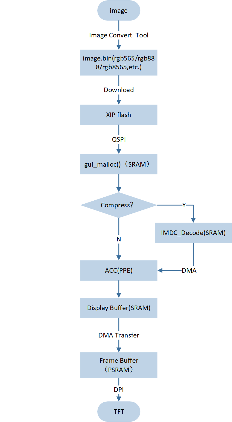
Graphic Data Loading Process
Load the program and drawing data from the external Flash to PSRAM, and display the drawing data to the TFT. The specific process is shown in the figure below Data Path.
User resource display file processing: Graphic resources are processed using the Image Convert Tool, and the image binary file is output, including the image attribute header (image size, compression, color format (RGB565, RGB888, etc.)), and User Data:
root.binis created.Download the flash area: Use the MPtool tool to burn into the EVB XIP flash area.
Read data in Flash: Use QSPI, 80MHz bandwidth, and double-edge data (DTR) reading method.
Allocate memory: Before loading image data, it is necessary to allocate enough memory to store image pixel data (SRAM) according to the image size and format.
Compressed graphics pixel processing: The GUI image control indexes the address of the file in the flash by the image name, determines whether it is compressed, and needs to be decompressed if compressed, and is moved from the flash to the SRAM via DMA. The pixel is processed by the PPE pixel processing engine and stored in the previously allocated memory (SRAM).
-
Uncompressed graphics pixel processing: The GUI image control indexes the address of the file in the flash by the image name, determines whether it is compressed, and the uncompressed image is directly moved from the flash to the SRAM via DMA, processed by the PPE, and stored in the SRAM.
Note
PPE processes uncompressed data, and compressed data needs to be decompressed before it can be processed by PPE.
TFT display: After PPE processing, the pixel is moved to the PSRAM cache via DMA, and finally displayed on the screen via LCDC (OPI).
Data Path
PPE1.0 Performance Measurement
As shown below, seven tasks have been created for the user application:
-
PPE function: Blend, unit ms, Destination fixed format RGB565, screen size 480 by 480, error no more than 180us.
-
PPE:RGB565 Bypass mode (Source to Destination),unit:ms
SRAM
PSRAM
FLASH
7.178
7.18
PSRAM
5.64
13.524
SRAM
3.426
5.228
-
PPE:RGB565 source over mode (Source to Destination),unit:ms
SRAM
PSRAM
FLASH
7.474
13.642
PSRAM
5.918
20.846
SRAM
5.04
13.528
-
PPE:RGB8565 Bypass mode (Source to Destination),unit:ms
SRAM
PSRAM
FLASH
11.518
11.52
PSRAM
8.754
16.932
SRAM
4.488
5.23
-
PPE:RGB8565 source over mode (Source to Destination),unit:ms
SRAM
PSRAM
FLASH
11.775
14.546
PSRAM
8.99
24.11
SRAM
5.775
13.528
-
-
PPE function: Scale, unit ms, Destination fixed format RGB565, error does not exceed 80us.
-
PPE: 480 * 480 reduced by 2 times to 240 * 240 (Source to Destination), unit: ms
SRAM
PSRAM
FLASH
3.762
3.758
PSRAM
2.891
4.83
SRAM
1.54
1.493
-
PPE: 240 * 240, enlarged 2 times to 480 * 480 (Source to Destination), unit: ms
SRAM
PSRAM
FLASH
16.119
16.119
PSRAM
7.78
13.507
SRAM
3.214
5.167
-
Port Adaptation LCD
LCD screen adaptation needs to be adapted according to the screen cache situation. In this sample, the default condition is that PSRAM is used as the screen cache. To select GRAM as the screen cache, please refer to the GRAM section.
RAMLESS
Screen resolution information configuration (refer to the screen specification), mainly configure LCD width, height, pixel depth information. Take the example as an example, modify the corresponding parameters in the
EK9716_800480_rgb.hheader file.
#define EK9716_800480_LCD_WIDTH                   800  //Screen width
#define EK9716_800480_LCD_HEIGHT                  480  //Screen Height
#define EK9716_DRV_PIXEL_BITS                     16  //Pixel Depth
The section height needs to be configured. The height selection depends on the actual situation. In the example project, LCD_SECTION_HEIGHT = 10 is configured. The corresponding parameters can be modified in
gui_port_dc.c.
#define LCD_SECTION_HEIGHT 10
PSRAM needs to be configured with address information as screen cache. In
gui_port_dc.c, the example of configuring PSRAM cache for framebuffer is as follows:
static uint32_t video_buffer1 = SPIC1_ADDR;
static uint32_t video_buffer2 = (SPIC1_ADDR + EK9716_800480_LCD_WIDTH * EK9716_800480_LCD_HEIGHT * 2);
static uint32_t current_buffer = SPIC1_ADDR;
Screen Display DMA Transfer API API
Description
memcpy_by_dma_start ()DMA starts to transfer data
memcpy_by_dma_done ()wait for DMA transfer to complete
-
Other interface APIs of LCD driver layer, corresponding to
gui_port_dc.c.LCD Screen Display Driver Interface API
Description
drv_lcd_get_screen_width ()get screen width
drv_lcd_get_screen_height ()get screen height
drv_lcd_get_pixel_bits ()get screen pixel depth
port_gui_lcd_power_on ()screen startup
port_gui_lcd_power_off ()screen shutdown
gui_port_dc_init ()initialize LCD
port_gui_lcd_update ()update each segment of LCD
drv_lcd_update ()transfer the specified buffer to the screen
Update the contents of the frame buffer to the LCD screen using the
port_gui_lcd_updateinterface. By default, the screen uses PSRAM as the frame buffer.void port_gui_lcd_update(struct gui_dispdev *dc) { uint32_t i = dc->section_count; uint32_t total_section_cnt = (drv_lcd_get_screen_height() / LCD_SECTION_HEIGHT + (( drv_lcd_get_screen_height() % LCD_SECTION_HEIGHT) ? 1 : 0)); uint32_t section = (drv_lcd_get_screen_height() / LCD_SECTION_HEIGHT + (( drv_lcd_get_screen_height() % LCD_SECTION_HEIGHT) ? 1 : 0)); #if 0 //gram if (i == 0) { drv_lcd_set_window(0, dc->fb_height * dc->section_count, dc->fb_width, dc->fb_height); drv_lcd_start_transfer(dc->frame_buf, dc->fb_width * dc->fb_height); } else if (i == section - 1) { uint32_t last_height = dc->screen_height - dc->section_count * dc->fb_height; drv_lcd_transfer_done(); drv_lcd_set_window(0, dc->fb_height * dc->section_count, dc->fb_width, last_height); drv_lcd_start_transfer(dc->frame_buf, dc->fb_width * last_height); drv_lcd_transfer_done(); } else { drv_lcd_transfer_done(); drv_lcd_set_window(0, dc->fb_height * dc->section_count, dc->fb_width, dc->fb_height); drv_lcd_start_transfer(dc->frame_buf, dc->fb_width * dc->fb_height); } #else //psram void *dst = (void *)(current_buffer + i * dc->fb_width * dc->fb_height * source_bytes_per_pixel); if (i == 0) { memcpy_by_dma_start(dst, dc->frame_buf, dc->fb_width * dc->fb_height * source_bytes_per_pixel); } else if (i == section - 1) { uint32_t last_height = dc->screen_height - dc->section_count * dc->fb_height; memcpy_by_dma_done(); memcpy_by_dma_start(dst, dc->frame_buf, dc->fb_width * last_height * source_bytes_per_pixel); memcpy_by_dma_done(); drv_lcd_update((uint8_t *)current_buffer, 0, 0, drv_lcd_get_screen_width(), drv_lcd_get_screen_height()); if (current_buffer == video_buffer1) { current_buffer = video_buffer2; } else if (current_buffer == video_buffer2) { current_buffer = video_buffer1; } else { current_buffer = video_buffer1; } } else { memcpy_by_dma_done(); memcpy_by_dma_start(dst, dc->frame_buf, dc->fb_width * dc->fb_height * source_bytes_per_pixel); } #endif }
GRAM
Compared with PSRAM, GRAM has a slower read and write speed. Therefore, for scenes that require frequent updates of display content (such as animation or video playback), GRAM may not be suitable. The following explains several key functions required for screen updates:
Wait for the previous section to be transferred: middle layer API interface
rtk_lcd_hal_transfer_done(), bottom layer implementationrtk_lcd_hal_transfer_done().
void rtk_lcd_hal_transfer_done(void)
{
    LCDC_HANDLER_DMA_FIFO_CTRL_t handler_reg_0x18;
    do
    {
        handler_reg_0x18.d32 = LCDC_HANDLER->DMA_FIFO_CTRL;
    }
    while (handler_reg_0x18.b.dma_enable != RESET);
    LCDC_HANDLER_OPERATE_CTR_t handler_reg_0x14;
    do
    {
        handler_reg_0x14.d32 = LCDC_HANDLER->OPERATE_CTR;
    }
    while (handler_reg_0x14.b.auto_write_start != RESET);

    LCDC_ClearDmaFifo();  // clear DMA FIFO
    LCDC_ClearTxPixelCnt();  // clear the pixel counter for the transfer
    LCDC_AXIMUXMode(LCDC_FW_MODE);  // switch AXI MUX mode to FW mode
    LCDC_Cmd(DISABLE);  // disable LCD controller
}
Set the drawing area: the middle layer API interface
rtk_lcd_hal_set_window(), corresponding to the underlying implementationrtk_lcd_hal_set_window().
void rtk_lcd_hal_set_window(uint16_t xStart, uint16_t yStart, uint16_t w, uint16_t h)
{
    uint8_t data[4];
    uint16_t xEnd = xStart + w - 1;
    uint16_t yEnd = yStart + h - 1;

    xStart = xStart + 0x14;
    xEnd = xEnd + 0x14;

    data[0] = xStart >> 8;
    data[1] = xStart & 0xff;
    data[2] = xEnd >> 8;
    data[3] = xEnd & 0xff;
    incna3311_cmd_param4(0x2A, data);


    data[0] = yStart >> 8;
    data[1] = yStart & 0xff;
    data[2] = yEnd >> 8;
    data[3] = yEnd & 0xff;
    incna3311_cmd_param4(0x2B, data);

    uint32_t len_byte = (xEnd - xStart + 1) * (yEnd - yStart + 1) * OUTPUT_PIXEL_BYTES;
    incna3311_enter_data_output_mode(len_byte);
}
Start from the frame buffer transfer: the middle layer API interface
rtk_lcd_hal_start_transfer(), corresponding to the bottom layer implementationrtk_lcd_hal_start_transfer().
void rtk_lcd_hal_start_transfer(uint8_t *buf, uint32_t len)
{

#if (DMA_LINKLIST == 0)
    LCDC_DMA_InitTypeDef LCDC_DMA_InitStruct = {0};
    LCDC_DMA_StructInit(&LCDC_DMA_InitStruct);
    LCDC_DMA_InitStruct.LCDC_DMA_ChannelNum          = LCDC_DMA_CHANNEL_NUM;
    LCDC_DMA_InitStruct.LCDC_DMA_DIR                 = 4;
    LCDC_DMA_InitStruct.LCDC_DMA_SourceInc           = LCDC_DMA_SourceInc_Inc;
    LCDC_DMA_InitStruct.LCDC_DMA_DestinationInc      = LCDC_DMA_DestinationInc_Fix;
    LCDC_DMA_InitStruct.LCDC_DMA_SourceDataSize      = LCDC_DMA_DataSize_Word;
    LCDC_DMA_InitStruct.LCDC_DMA_DestinationDataSize = LCDC_DMA_DataSize_Word;
    LCDC_DMA_InitStruct.LCDC_DMA_SourceMsize         = LCDC_DMA_Msize_8;
    LCDC_DMA_InitStruct.LCDC_DMA_DestinationMsize    = LCDC_DMA_Msize_8;
    LCDC_DMA_InitStruct.LCDC_DMA_SourceAddr          = (uint32_t)buf;
    LCDC_DMA_InitStruct.LCDC_DMA_Multi_Block_En     = 0;
    LCDC_DMA_Init(LCDC_DMA_CHANNEL_INDEX, &LCDC_DMA_InitStruct);
#else
    LCDC_DMA_InitTypeDef LCDC_DMA_InitStruct = {0};
    LCDC_DMA_StructInit(&LCDC_DMA_InitStruct);
    LCDC_DMA_InitStruct.LCDC_DMA_ChannelNum          = LCDC_DMA_CHANNEL_NUM;
    LCDC_DMA_InitStruct.LCDC_DMA_DIR                 = 4;
    LCDC_DMA_InitStruct.LCDC_DMA_SourceInc           = LCDC_DMA_SourceInc_Inc;
    LCDC_DMA_InitStruct.LCDC_DMA_DestinationInc      = LCDC_DMA_DestinationInc_Fix;
    LCDC_DMA_InitStruct.LCDC_DMA_SourceDataSize      = LCDC_DMA_DataSize_Word;
    LCDC_DMA_InitStruct.LCDC_DMA_DestinationDataSize = LCDC_DMA_DataSize_Word;
    LCDC_DMA_InitStruct.LCDC_DMA_SourceMsize         = LCDC_DMA_Msize_8;
    LCDC_DMA_InitStruct.LCDC_DMA_DestinationMsize    = LCDC_DMA_Msize_8;
    LCDC_DMA_InitStruct.LCDC_DMA_SourceAddr          = 0;

    LCDC_DMA_InitStruct.LCDC_DMA_Multi_Block_Mode   =
        LLI_TRANSFER;//LLI_TRANSFER or LLI_WITH_CONTIGUOUS_SAR
    LCDC_DMA_InitStruct.LCDC_DMA_Multi_Block_En     = 1;
    LCDC_DMA_InitStruct.LCDC_DMA_Multi_Block_Struct  = LCDC_DMA_LINKLIST_REG_BASE + 0x50;
    LCDC_DMA_Init(LCDC_DMA_CHANNEL_INDEX, &LCDC_DMA_InitStruct);

    LCDC_SET_GROUP1_BLOCKSIZE(ICNA3311_LCD_WIDTH * INPUT_PIXEL_BYTES);
    LCDC_SET_GROUP2_BLOCKSIZE(ICNA3311_LCD_WIDTH * INPUT_PIXEL_BYTES);

    /*16 pixel aligned for GPU*/
    LCDC_DMALLI_InitTypeDef LCDC_DMA_LLI_Init = {0};
    LCDC_DMA_LLI_Init.g1_source_addr = (uint32_t)buf;
    LCDC_DMA_LLI_Init.g1_sar_offset = ICNA3311_LCD_WIDTH * INPUT_PIXEL_BYTES * 2;

    LCDC_DMA_LLI_Init.g2_source_addr = (uint32_t)(buf + ICNA3311_LCD_WIDTH * INPUT_PIXEL_BYTES);
    LCDC_DMA_LLI_Init.g2_sar_offset = ICNA3311_LCD_WIDTH * INPUT_PIXEL_BYTES * 2;
    LCDC_DMA_LinkList_Init(&LCDC_DMA_LLI_Init,
                           &LCDC_DMA_InitStruct);//LLI_TRANSFER or LLI_WITH_CONTIGUOUS_SAR
#endif

    LCDC_ClearDmaFifo();  // clear DMA FIFO
    LCDC_ClearTxPixelCnt();  // Clear the pixel counter for the transfer

    LCDC_SwitchMode(LCDC_AUTO_MODE);  // Switch the LCD controller to automatic mode
    LCDC_SwitchDirect(LCDC_TX_MODE);  // Switch the LCD controller to transmit mode
    LCDC_SetTxPixelLen(len);  // Set the number of pixels to send

    LCDC_Cmd(ENABLE);  //Enable LCD Controller
#if DMA_LINKLIST
    LCDC_DMA_MultiBlockCmd(ENABLE);  // In DMA linked list mode, enable multi-block transfer
#endif
    LCDC_DMAChannelCmd(LCDC_DMA_CHANNEL_NUM, ENABLE);  // Enable DMA channel
    LCDC_DmaCmd(ENABLE);  // Enable DMA
#if (TE_VALID == 1)
    LCDC_TeCmd(ENABLE);  // If TE is valid, the TE (Transfer End) signal is enabled
#endif
#if (TE_VALID == 0)
    LCDC_AutoWriteCmd(ENABLE);  // If TE is invalid, the automatic write command is enabled
#endif

}
-
Tearing effect configuration to prevent screen tearing.
The hardware has a TE signal pin, which is configured as a falling edge trigger. At the same time, in the TE callback function, modify the TE flag.
Screen parameter configuration, completely refer to the situation where PSRAM is used as screen cache, configure basic screen information, and modify
sectionheight.
Reference
RTL8772GWP_Cluster_SDK_Programming_Guide R2