HID Proprietary Protocol Specification
This protocol is a Realtek private wireless protocol that supports point-to-point communication and is suitable for HID-related applications.
Features of this protocol:
Support 4K ultra-high reporting rate
Support multiple retransmission mechanisms to meet the reliability requirements of different services
Use frequency hopping technology to improve anti-interference ability
Support pairing for fast binding
Support automatic switching to low power mode when idle
This protocol is divided into two layers: physical layer and link layer. The physical layer defines the channel, RF parameters and modulation related. The link layer defines functions such as pairing, connection, and link maintenance, and provides communication services for the application layer. The details of this protocol are described later in this article.
Physical Layer
Physical Channel
The working frequency band is the 2.4GHz ISM frequency band, which is 2400~2483.5MHz.
The center frequency and number of channels are configurable. The default is 12 channels, respectively 2432, 2447, 2462, 2477, 2407, 2422, 2437, 2452, 2442, 2457, 2472, 2413MHz.
Modulation
The features are as follows:
Bandwidth Time Factor = 0.5
Modulation Index = 0.5
Symbol Rate = 2 Mbps
Link Layer
Frame Format
The frame format is as shown in the following table. Except for the CRC field, whose endianness is MSByte and MSBit, the endianness of all other fields is LSByte and LSBit.
Field Name |
Length (bit) |
Description |
|---|---|---|
PREAMBLE |
8 |
If the lsb of the access address is 0, the value is 0xAA If the lsb of the access address is 1, the value is 0x55 |
ACCESS ADDRESS |
32 |
logical channel identifier |
1 |
acknowledge bit |
|
7 |
sequence |
|
LENGTH |
7 |
the byte length of the payload field |
PAYLOAD |
n*8 |
command or application data with variable length in bytes |
CRC |
8 |
checksum |
Frame Coding
CRC checksum and whitening code will be used when sending and receiving data. See the following chapters for detailed parameters.
CRC
The verification range is from the access address to the payload.
The polynomial is 0x107.
The initial value is 0xff.
Whitening
The coding range is from the ACK to the CRC.
The polynomial is 0x91.
The initial value is based on the channel index.
Device Role
In HID applications, point-to-point communication occurs between the dongle and the peripheral device such as mice. This protocol defines the peripheral device as the master device, and the dongle as the slave device.
State
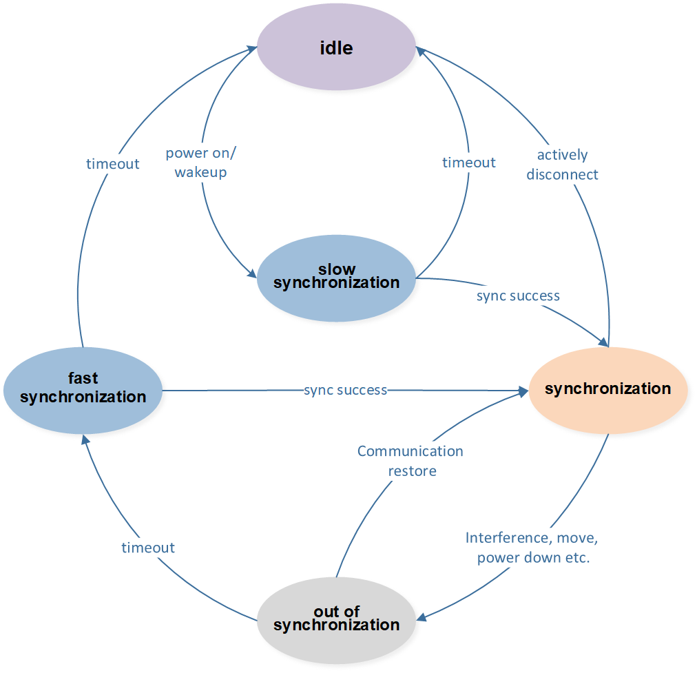
By default, the two devices are in an idle state, that is, not communicating. When two devices try to establish a connection, the master and slave are out of sync and may be operating on different physical channels and therefore cannot communicate immediately. At this time, the two will synchronize to the same physical channel through frequency hopping to establish a stable connection. This process is called the slow sync state. Then, both parties continue to conduct ping-pong communication on the physical channel, which is called the synchronization state. Due to interference, device movement, power outage, etc., the synchronized devices may lose synchronization and be unable to hear each other's messages, which is called an out-of-sync state.
The out-of-synchronization state may return to normal and switch back to the synchronization state; it may also time out. After the timeout, the device will enter the reconnection process. At this time, the master device and the slave device are also out of sync and may work on different physical channels. The two will try to synchronize to the same physical channel through frequency hopping again to restore the connection. If the recovery is successful, it switches back to the synchronization state, otherwise it enters the idle state.
Among these states, only the connection and reconnection states will perform channel frequency hopping. The frequency hopping in the connection process uses all channels, and the frequency hopping frequency is low, so it is called slow synchronization; the frequency hopping in the return connection process uses part of the channel, and the frequency hopping frequency is high, so it is called fast synchronization.
In summary, the status of the device is divided into: idle, slow synchronization, synchronization, out-of-synchronization, and fast synchronization. The following chapters will introduce the behavior of each state.
Idle
No communication is performed in the idle state. When the device is just powered on, the device is disconnected, or it is actively disconnected after a long period of inactivity, it will enter the idle state.
Slow Synchronization
The master device adopts the full channel sequential frequency hopping method.
The slave device evaluates all channels and selects the best channel.
The frequency hopping frequencies of the master device and the slave device are Fm and Fs respectively. The default Fm = 1KHz and Fs = 5Hz.
Synchronization
The device will periodically perform a single ping-pong communication, and this period is the synchronization interval. In order to balance power consumption and performance, the master device can adjust the synchronization interval.
Out of Synchronization
The master device will wait for a response from the slave device after sending a message at each synchronization interval. If the correct response is not received after the timeout, it is considered to have lost synchronization.
The slave device will continue to listen to the channel to receive messages. If it times out and does not hear the message from the master device, it is considered to have lost synchronization.
The out-of-synchronization timeout period is recorded as synchronization lost timeout period. The number of synchronizations of the master device before the out-of-synchronization timeout is the synchronization lost timeout period divided by the synchronization interval. The number of synchronizations needs to be guaranteed to be 2 times or more. If it is too small, it will frequently lose synchronization and time out, and then enter the fast synchronization state and interrupt normal communication, affecting communication efficiency.
Fast Synchronization
The frequency hopping channel range of the master device and the slave device is a channel subset composed of the channel segment where the current channel is located, which speeds up the recovery of synchronization at both ends. The channels are divided into 3 groups by default, namely {2432, 2447, 2462, 2477}, {2407, 2422, 2437, 2452}, {2442, 2457, 2472, 2413}. For example, the synchronization channel is 2422 MHz, and the fast synchronization frequency hopping frequencies are 2407, 2422, 2437, and 2452 MHz.
The master device uses sequential frequency hopping, and the slave device selects the best channel through channel evaluation.
State Machine
To sum up, the relationship between each state is as shown in Figure State Machine.

State Machine
Logic Channel
According to the value of access address, physical channels are divided into two types of logical channels: broadcast channels and data channels.
Broadcast channel: is used for device pairing, and the access address value is fixed at 0x8EBE89D6.
Data channel: is used for data communication, and the access address is specified by the slave device during the pairing process.
Attention
There is only one broadcast channel, which is shared by all devices and is only used when paired. There are approximately countless data channels, which are private communication channels for each pair of master and slave devices.
Acknowledge and Retransmit
The devices at both ends will maintain their own sending sequence number SEQ field. The SEQ is incremented every time a new packet is sent, and starts from 0 after overflow. If the device correctly receives the peer message, it will set the ACK field to 1 in its next message, that is, send ACK; if it receives an error, or does not receive it, it will set the ACK field to 0, that is, send NACK.
After the sender sends a message, if an ACK is received, it indicates that the message was sent successfully. If no response is received, or a NACK is received, it can be retransmitted or actively discarded. In other words, packet loss is allowed.
According to the number of retransmissions, messages are divided into the following four categories:
Zero retransmission: The message is only sent once regardless of whether it is responded to or not.
Limited retransmission: If the message is not responded to, it will be retransmitted. If there is no response after retransmitting a certain number of times, the retransmission will be cancelled.
Infinite retransmission: If the message is not answered, it will be retransmitted until it is answered.
Dynamic retransmission: If a message is not answered and needs to be retransmitted, if there are other messages to be sent, the retransmission will be canceled. If there are no other messages to be sent, the retransmission will continue.
Pairing
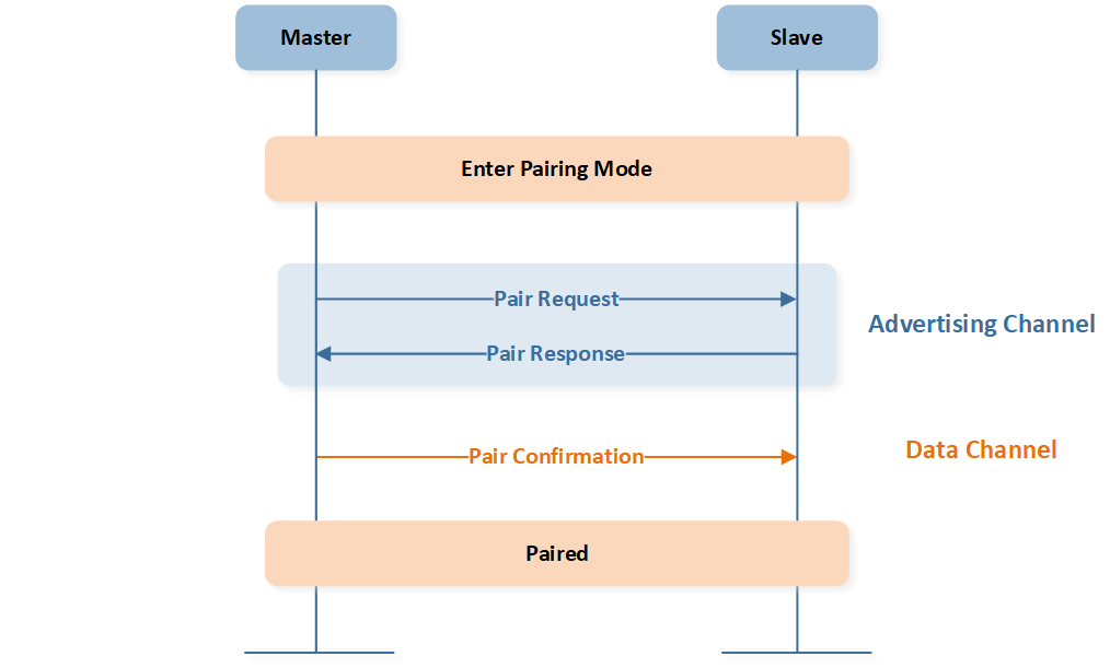
The binding relationship between master and slave devices is determined through the pairing process. When pairing, the master device sends a pairing request on the broadcast channel. If the slave device is also in the pairing state, it will respond with a pairing response and tell the master device the data channel and other pairing information.
Then, the two parties perform a handshake on the data channel to confirm that the pairing is successful. The pairing process is shown in Figure Pairing Procedure.

Pairing Procedure
Connect
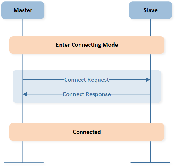
Two bound devices establish a connection through the connection process, that is, they enter the synchronization state from the slow synchronization state. When establishing a connection, the master device sends a connection request and the slave device replies with a connection response, as shown in Figure Connection Procedure.

Connection Procedure
Heartbeat
If there is no data interaction between the master and slave devices in synchronization state, they can maintain the connection through the heartbeat mode. The heartbeat mode reduces the communication frequency, which reduces the power consumption of the master device.
When the master device has no data to send and the slave device did not send data last time, it will actively send a heartbeat message.
When the slave device responds with an empty message, the negotiation between the two parties is successful, and the master device will send heartbeat messages again according to the agreed interval.
When the slave device responds to a non-null message, it means that the slave device may have data to send, and the master device cannot enter the heartbeat state and needs to continue fast communication.
During the heartbeat cycle, the master device can send non-heartbeat messages at any time to interrupt the heartbeat process, and both parties will immediately exit the heartbeat maintenance state and enter the high-speed communication state.
An example of the heartbeat entry and exit process is shown in Figure Heartbeat Procedure.

Heartbeat Procedure
PDU
The payload part in the frame format is the protocol message PDU. The link layer protocol message PDU and the application layer protocol message PDU share the same format and its opcode, which are defined as shown in the following table.
Field Name |
Length (byte) |
Description |
|---|---|---|
OPCODE |
1 |
operation code 0x00~0x0f reserved for the link layer 0x10~0xff reserved for the application layer |
PARAMETER |
n |
message parameters |
The opcodes of the packets used by the link layer protocol are shown as follows.
Opcode Value |
Message Name |
Description |
|---|---|---|
0x00 |
Empty Packet |
Used to maintain the link. |
0x01 |
Pairing Request |
Sent by the master device in the pairing state to find the slave device in the pairing state at the same time. |
0x02 |
Pairing Response |
Pairing reply sent from the slave device. |
0x03 |
Pairing Confirmation |
Sent by the master device to confirm pairing status. |
0x04 |
Connect Request |
When the master device establishes a connection, it sends a connection request to find the slave device that is also in the connection state. |
0x05 |
Connect Response |
Connection reply sent from the slave device. |
0x06 |
Heartbeat |
Sent by the master device to reduce the communication frequency while maintaining the link. |
Application layer protocols are beyond the scope of this article. The following chapters introduce the specific functions and parameters of each link layer protocol message.
Empty Packet
Empty packet is used to maintain the link. Empty packet has no parameters.
Pairing Request
The master device in the pairing state sends the pairing request message to find the slave device in the pairing state at the same time and initiate the pairing process.
The parameters are as follows:
Field |
Size (Bytes) |
Description |
|---|---|---|
Sync Interval |
2 |
synchronization interval in unit of us |
Pairing Response
Sent by the slave device in the pairing state to respond to the pairing request.
The parameters are as follows:
Field |
Size (Bytes) |
Description |
|---|---|---|
Access Address |
4 |
access address used for the data channel |
Pairing Confirmation
The first packet sent by the master device after switching from the broadcast channel to the data channel. Pairing confirmation has no parameters.
Connect Request
Sent by the master device in the connecting state to find the slave device in the connecting state at the same time and initiate the connection process.
The parameters are as follows:
Field |
Size (Bytes) |
Description |
|---|---|---|
Sync Interval |
2 |
synchronization interval in units of us |
Connect Response
Sent by a slave device in the connecting state in response to a connect request. The connect response message has no parameters.
Heartbeat
Sent by the master device, sent when the master device decides to reduce the communication frequency.
The parameters are as follows:
Field |
Size (Bytes) |
Description |
|---|---|---|
Heartbeat Interval |
2 |
heartbeat interval in units of ms |