Charger
The whole charger system can be split into two layers: the upper layer and the lower layer.
The upper layer is app_charger (app_charger.c), which reports the state of charge (SoC¹, which is a term for charge, State of Charge) and charger state to other modules in the APP layer. It is an abstract wrapper to hide differences between the internal charger and the external charger.
The lower layer is the implementation of the charger that is usually the internal charger, but an external charger is an alternative.
There is an rtk_charger.c in the APP project as a wrapper for the internal charger because the internal charger was placed in ROM. On the other hand, the external charger should be implemented in the APP project completely.
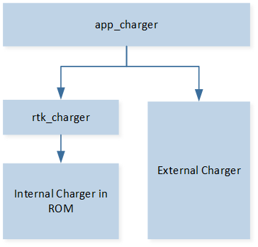
Charger Architecture
How to Link rtk_charger with app_charger?
The internal charger from RTK is useful, but an external one is also optional. As described above, if an external charger is to be used, it should interface with app_charger after finishing the driver for the external charger. Regarding the internal charger, RTK SDK has already implemented it in rtk_charger.c.
If the internal charger is to be used, please set RTK_CHARGER_ENABLE to 1; otherwise, set it to 0. All app_charger operations will switch between external and internal APIs as shown in the code below.
T_APP_CHARGER_STATE app_charger_get_charge_state(void)
{
   T_APP_CHARGER_STATE app_charger_state = APP_CHARGER_STATE_ERROR;

#if RTK_CHARGER_ENABLE
   T_CHARGER_STATE rtk_charger_state = rtk_charger_get_charge_state();

   app_charger_state = app_charger_state_convert(rtk_charger_state);
#endif

   return app_charger_state;
}

uint8_t app_charger_get_soc(void)
{
   uint8_t soc = 0;

#if RTK_CHARGER_ENABLE
   soc = rtk_charger_get_soc();
#endif

   return soc;
}
Generally, the major task for internal or external charger interfacing is to provide state of charge and charger state to app_charger both by call and callbacks.
By call, add the charger API in app_charger_get_charge_state and app_charger_get_soc. The content of these functions is displayed as code above.
By callbacks, register callbacks to the charger module (external charger). These callbacks finally send state of charge and charger state in messages by app_io_msg_send. These messages will be handled in app_charger_handle_msg. Then app_charger is responsible for reporting information to other APP modules. Follow the flow of internal charger (RTK charger).
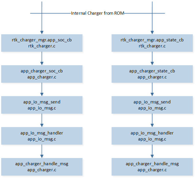
Internal Charger Flow
Note
APP layer smoothly supports state of charge report during battery discharge. It will process state of charge reported by internal charger and calculate the average. Also, if state of charge drops greater than 3% at one time, app_charger will ignore this report to avoid unexpected noise. This feature can be disabled by turning off the macro
F_APP_SMOOTH_BAT_REPORTinapp_flags.h.APP layer supports battery report de-bounce. State of charge will be filtered by APP layer, so it can only drop in discharge mode and rise in charge mode.
Internal Charger
There is a built-in internal charger system in RTK, which includes the charger module and the discharger module, as shown in Charger System.
The main functionality of the internal charger module includes battery charging, error handling, state of charge tracking, and status reporting with a callback function. The main functionality of the internal discharger module includes state of charge tracking and status reporting with a callback function. When the charger module is running, the system will not be allowed to enter low power mode. When the discharger module is running, the system is allowed to enter low power mode. The charger module and discharger module will not coexist.
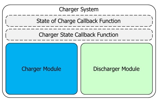
Charger System
Principle of Internal Charger
CC and CV control the charger system.
Considering the safety and efficiency of Lithium-ion battery charging, the charging process is divided into three stages.
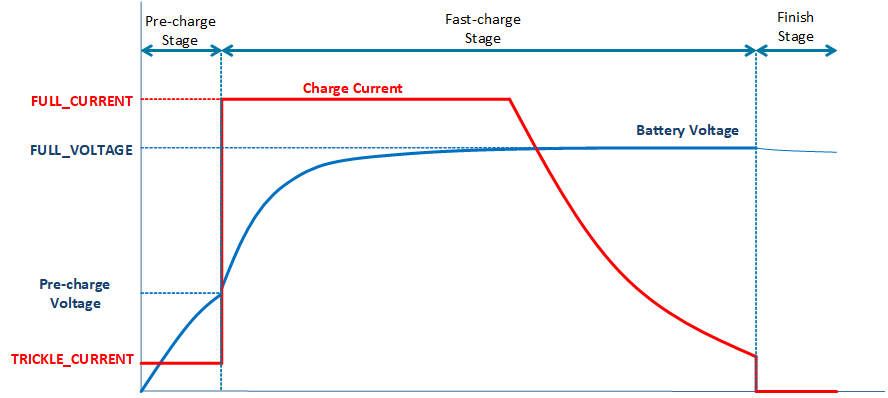
Charger Curve
Pre-charge Stage
Before the battery voltage reaches the pre-charge voltage, the maximum (trickle) current can only be 1/10 (typically) of the general charge (CC). The excessive current will be converted into heat, which hastens the death of batteries.
Fast-charge Stage
When the battery voltage exceeds the pre-charge voltage, it is then allowed to enter the fast-charge stage. In this stage, the charging current should be limited (CC), and the charging voltage should be limited to the termination voltage (CV). In the early stage of fast-charge, the charging rate will be bound by the current limit. When the battery voltage is nearly at full voltage, the charging current will gradually decrease, and the charging rate will be bound by the limit voltage.
Finish Stage
When the charging current is lower than the end current, it means that the battery is fully charged. Set the current upper limit to 0 to end the charging.
Battery OCV and VBAT Terminal Voltage
The voltage value obtained by API charger_utils_get_batt_volt() is the OCV of the battery.
When charging, OCV = VBAT - charging current * battery resistance.
When discharging, OCV = VBAT + discharge current * battery resistance.
Therefore, the voltage value measured at the VBAT terminal is different from the value obtained by API charger_utils_get_batt_volt(). Note, the higher charging current leads to a higher voltage division in the internal resistance of the battery. To confirm the actual OCV when charging, users could measure the battery voltage separately when cutting off the charging line.
Charger Configured by MCUConfig Tool
Internal charger is configured by MCUConfig Tool. Refer to the ‘Charger’ chapter of the MCUConfig Tool User Guide.
Note
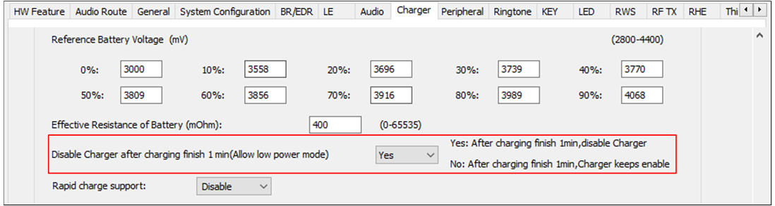
If the option Disable Charger after charging finish 1 min is on, the charger will be disabled after entering the finish state for 1 minute. This option is used to save power for the charging box. If the adapter in is detected, the charger will be enabled again automatically. So this option is preferred to be set in power-down mode instead of DLPS mode. The configuration in MCUConfig Tool is shown in the figure below.
If NTC is powered by PAD and uses RTK’s recommended hardware circuit for charger temperature detection, PAD rises slowly because of the capacitance on the hardware circuit, requiring a delay after pulling up PAD, use
platform_delay_msfor a 6 ms delay, oros_delayfor a 20 ms delay.The input voltage range of the charger temperature detection pin is 0V ~ 0.9V.
Disable Charger after Charging Finish 1 Minute
External BJT Charger
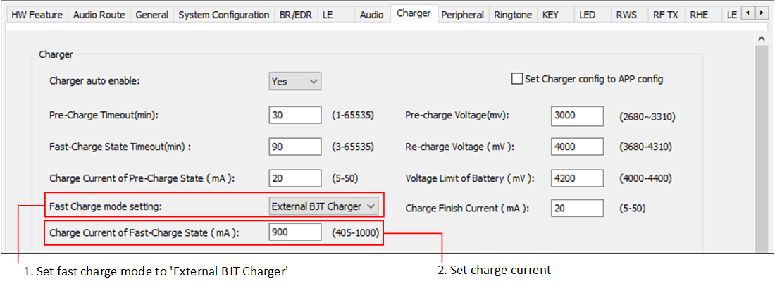
The External BJT Charger can be enabled for larger current charging for RTL87x3D, and the charging current is supported up to 405mA to 1000mA. The configuration in MCUConfig Tool is shown in High Current Charging Configuration.
Note, the voltage value measured at the VBAT terminal is different from the value obtained by API charger_utils_get_batt_volt(), details refer to Battery OCV and VBAT Terminal Voltage.
High Current Charging Configuration
Charger Thermal Protection
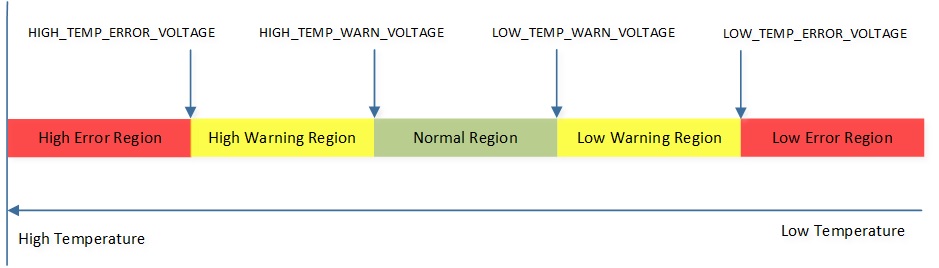
Users can configure 4 voltage levels corresponding to 2 warning temperatures and 2 error temperatures, as shown in Battery Temperature Regions.
Typically, from high temperature to low temperature, it would be HIGH_TEMP_ERROR_VOLTAGE, HIGH_TEMP_WARN_VOLTAGE, LOW_TEMP_WARN_VOLTAGE and LOW_TEMP_ERROR_VOLTAGE. The unit is mV.
Battery Temperature Regions
Reference Battery Voltage
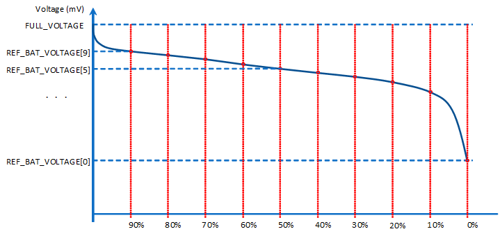
Ten battery voltage levels are used to estimate the state of charge, as shown in the Discharge Curve.
Discharge Curve corresponds to battery voltage levels from 0% to 90% (100% is obtained at the last trickle charge). It is recommended to discharge the battery from full to empty state of charge to get these 10 reference battery voltage levels for state of charge estimation. The unit is mV.
Discharge Curve
Internal Charger APIs from ROM
Internal Charger source code is implemented in ROM. APIs’ declarations are in charger_api.h.
charger_api_reg_state_of_charge_callbackRegister the user-defined callback function, which will be called by the charger module when the state of charge changes. The state of charge represents the quantity of electricity. Append the APP code according to the demand.
charger_api_unreg_state_of_charge_callbackUnregister the user-defined
STATE_OF_CHARGE_CALLBACKcallback function.charger_api_reg_charger_state_callbackRegister the user-defined callback function, which will be called by the charger module when the charger state (it is different from the state of charge mentioned above) changes.
charger_api_unreg_charger_state_callbackUnregister the user-defined
CHARGER_STATE_CALLBACKcallback function.-
Enable the charger module manually. IC’s ROM code calls it when the USB adapter is plugged in.
Note
It will cause a soft reset of the charger module and force the discharger module to be disabled if the discharger module is running.
-
Disable the charger module manually. IC’s ROM code calls it when the USB adapter is unplugged.
-
Enable the discharger module manually. IC’s ROM code calls it when the USB adapter is unplugged.
Note
It will cause a soft reset of the discharger module and force the charger module to be disabled if the charger module is running.
charger_api_disable_dischargerDisable the discharger module manually. IC’s ROM code calls it when the USB adapter is plugged in.
Note
When calling APIs 5 to 8 in the adapter callback to control the charger or discharger, it is necessary to turn off Charger auto enable and Battery detection support on the MCUConfig Tool.
charger_api_set_adapter_currentSet the maximum current of the adapter.
Note
It will trigger a soft reset of the charger module.
-
Set full charge current, the alias is general current (CC).
Note
It will trigger a soft reset of the charger module.
charger_api_get_state_of_chargeGet the state of charge. If the charger is in
CHARGER_MODULEorDISCHARGER_MODULE, the function returns auint8_tvalue (0~100). The return value means the battery’s quantity of electricity (0%~100%).Note
It returns 255 when the charger is in
NO_ACTIVE_MODULE.-
Get the charger module state.
-
Get the error code of the charger module.
Internal Charger APIs from charger_utils
-
Get the voltage of the battery.
Note
Please refer to Battery OCV and VBAT Terminal Voltage.
-
Get the current of the battery.
-
Get the temperature of the battery.
charger_utils_get_adapter_volt()Get the voltage of the adapter.
charger_utils_charger_auto_enable()Enable or disable the charger.
charger_utils_get_thermistor_enable_state()Get charger thermistor detection enable status.
-
Set the charge current of the pre-charge state, the timeout time of the pre-charge stage, the charge current of the fast-charge state, the timeout time of the fast-charge stage, and the voltage limit of the battery.
-
Get charge current of the pre-charge state, the timeout time of the pre-charge stage, the charge current of the fast-charge state, the timeout time of the fast-charge stage, and the voltage limit of the battery.
charger_utils_get_thermistor_1_pin()Get charging thermistor 1 ADC channel configurations.