Audio Route
The purpose of this document is to describe how to use the Audio Route module in the MCUConfig Tool. The audio routing capability of each IC can be demonstrated using the MCUConfig Tool. Customers can configure the routing relationship of each audio stream using the MCUConfig Tool.
This document contains the following information:
Audio Route Concepts
Audio Route indicates the static configuration of the physical data path. The Audio Route module is classified based on the Audio Category. The Audio Route module consists of Gateway configuration, Endpoint configuration, Logical IO configuration, and Physical IO configuration.
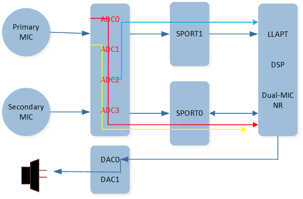
The figure shows a simplified Audio Route path between Codec and DSP.
Audio Route Path
As shown in the figure, the data collected by the microphone passes through an ADC channel of the Codec and flows to a SPORT RX channel to reach the DSP. After the data is processed by the DSP, it passes through a SPORT TX channel and then passes through the DAC channel of the Codec, and finally, is played out through the specific speaker.
The main function of the Audio Route module is to configure Gateway and Logical IO related parameters for an Audio Route path.
Audio Category
Audio Category is used to classify all streams transferred between the Host and the Controller. The streams that have the same control flows, usage scenarios, and functionalities should be classified as follows:
The table shows the types of Audio Category.
Category |
Description |
|---|---|
Audio |
Audio Playback Streams |
Voice |
Voice Uplink and Downlink Streams |
Record |
Voice Capture and Recognition Streams |
Line |
Line Streams |
Ringtone |
Ringtone Streams |
Voice Prompt |
Voice Prompt Streams |
APT |
Ambient Passthrough Streams |
LLAPT |
Low-latency Ambient Passthrough Streams |
ANC |
Ambient Noise Control Streams. |
VAD |
Voice Activity Detection Streams |
KWS |
Keyword Spotting Streams |
Pipe |
Codec Conversion Streams |
Gateway
A Gateway controls the inflow and outflow of multiple stream routing paths. These stream routing paths shall have the same configurations, such as sample rate, data length, channel length, and channel mode. The Host and the Controller shall support 2 Gateway types.
The table shows the types of Gateway.
Name |
Description |
|---|---|
SPORT |
I2S Interface |
SPDIF |
SPDIF Interface |
Each Gateway shall support at most 4 Gateway indexes per Gateway type. Currently, you can configure
SPORT0/1/2/3 and SPDIF0 through MCUConfig Tool. Each Gateway shall have two directions, including TX
and RX.
Logical IO
Logical IO refers to the logical input and output related to the functions provided by the DSP.
The table shows the types of Logical IO.
Name |
Value |
Description |
|---|---|---|
Audio Primary Out |
0x00 |
Audio Primary Out |
Audio Secondary Out |
0x01 |
Audio Secondary Out |
Audio Primary Reference Out |
0x02 |
Audio Primary Reference Out |
Audio Secondary Reference Out |
0x03 |
Audio Secondary Reference Out |
Voice Primary Out |
0x10 |
Voice Primary Out |
Voice Secondary Out |
0x11 |
Voice Secondary Out |
Voice Primary Reference Out |
0x12 |
Voice Primary Reference Out |
Voice Secondary Reference Out |
0x13 |
Voice Secondary Reference Out |
Voice Primary Reference In |
0x14 |
Voice Primary Reference In |
Voice Secondary Reference In |
0x15 |
Voice Secondary Reference In |
Voice Primary In |
0x16 |
Voice Primary In |
Voice Secondary In |
0x17 |
Voice Secondary In |
Voice Fusion In |
0x18 |
Voice Fusion In |
Voice Bone Conduction In |
0x19 |
Voice Bone Conduction Sensor In |
Record Primary Reference In |
0x20 |
Record Primary Reference In |
Record Secondary Reference In |
0x21 |
Record Secondary Reference In |
Record Primary In |
0x22 |
Record Primary In |
Record Secondary In |
0x23 |
Record Secondary In |
Record Fusion In |
0x24 |
Record Fusion In |
Record Bone Conduction In |
0x25 |
Record Bone Conduction Sensor In |
Line Primary Out |
0x30 |
Line Primary Out |
Line Secondary Out |
0x31 |
Line Secondary Out |
Line Primary Reference Out |
0x32 |
Line Primary Reference Out |
Line Secondary Reference Out |
0x33 |
Line Secondary Reference Out |
Line Primary Reference In |
0x34 |
Line Primary Reference In |
Line Secondary Reference In |
0x35 |
Line Secondary Reference In |
Line Left In |
0x36 |
Line Left In |
Line Right In |
0x37 |
Line Right In |
Ringtone Primary Out |
0x40 |
Ringtone Primary Out |
Ringtone Secondary Out |
0x41 |
Ringtone Secondary Out |
Ringtone Primary Reference Out |
0x42 |
Ringtone Primary Reference Out |
Ringtone Secondary Reference Out |
0x43 |
Ringtone Secondary Reference Out |
Voice Prompt Primary Out |
0x50 |
Voice Prompt Primary Out |
Voice Prompt Secondary Out |
0x51 |
Voice Prompt Secondary Out |
Voice Prompt Primary Reference Out |
0x52 |
Voice Prompt Primary Reference Out |
Voice Prompt Secondary Reference Out |
0x53 |
Voice Prompt Secondary Reference Out |
APT Primary Out |
0x60 |
APT Primary Out |
APT Secondary Out |
0x61 |
APT Secondary Out |
APT Primary Reference Out |
0x62 |
APT Primary Reference Out |
APT Secondary Reference Out |
0x63 |
APT Secondary Reference Out |
APT Primary Reference In |
0x64 |
APT Primary Reference In |
APT Secondary Reference In |
0x65 |
APT Secondary Reference In |
APT Front Left In |
0x66 |
APT Front Left In |
APT Front Right In |
0x67 |
APT Front Right In |
APT FF Left In |
0x68 |
APT FF Left In |
APT FF Right In |
0x69 |
APT FF Right In |
APT FB Left In |
0x6A |
APT FB Left In |
APT FB Right In |
0x6B |
APT FB Right In |
APT Bone Left In |
0x6C |
APT Bone Left In |
APT Bone Right In |
0x6D |
APT Bone Right In |
LL-APT Primary Out |
0x70 |
Low Latency APT Primary Out |
LL-APT Secondary Out |
0x71 |
Low Latency APT Secondary Out |
LL-APT Primary Reference Out |
0x72 |
Low Latency APT Primary Reference Out |
LL-APT Secondary Reference Out |
0x73 |
Low Latency APT Secondary Reference Out |
LL-APT Primary Reference In |
0x74 |
Low Latency APT Primary Reference In |
LL-APT Secondary Reference In |
0x75 |
Low Latency APT Secondary Reference In |
LL-APT Left In |
0x76 |
Low Latency APT Left In |
LL-APT Right In |
0x77 |
Low Latency APT Right In |
ANC Primary Out |
0x80 |
ANC Primary Out |
ANC Secondary Out |
0x81 |
ANC Secondary Out |
ANC Primary Reference Out |
0x82 |
ANC Primary Reference Out |
ANC Secondary Reference Out |
0x83 |
ANC Secondary Reference Out |
ANC Primary Reference In |
0x84 |
ANC Primary Reference In |
ANC Secondary Reference In |
0x85 |
ANC Secondary Reference In |
ANC FF Left In |
0x86 |
ANC Feedforward Left In |
ANC FF Right In |
0x87 |
ANC Feedforward Right In |
ANC FB Left In |
0x88 |
ANC Feedback Left In |
ANC FB Right In |
0x89 |
ANC Feedback Right In |
VAD Primary Reference In |
0x90 |
VAD Primary Reference In |
VAD Secondary Reference In |
0x91 |
VAD Secondary Reference In |
VAD Primary In |
0x92 |
VAD Primary In |
VAD Secondary In |
0x93 |
VAD Secondary In |
Endpoint
Endpoint defines the peripheral interface type for the physical data paths. Endpoint consists of SPK, MIC, AUX and SPDIF physical entity input and output.
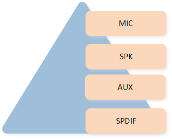
The figure shows types of Endpoint.
Endpoint Type
Note
MIC indicates the microphone input Endpoint.
SPK indicates the speaker output Endpoint.
AUX indicates the auxiliary input Endpoint or the auxiliary output Endpoint.
SPDIF indicates the SPDIF input Endpoint or the SPDIF output Endpoint.
Physical IO
The Physical IO defines the hardware driver layer interface enumerations for the corresponding IO Endpoint. Apparently, the Physical IO enumerations of each IO Endpoint type are coupled with the underlying hardware capabilities.
The table shows the parameter description of Physical IO.
IO Name |
Parameter List |
|---|---|
SPK |
Physical Speaker1/2 |
MIC |
Physical Microphone 1/2/3/4 |
AUX |
AUX-IN Left/Right Channel |
SPDIF |
SPDIF Interface 0 |
Audio Route Path
An audio path is constructed from one or more Audio Route paths.
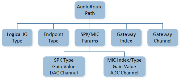
The figure shows the components of an Audio Route path.
Audio Route Path
As shown in the figure, an Audio Route path consists of the Logical IO Type, the Endpoint Type, SPK and MIC parameters, Gateway Index, and Gateway Channel. The parameter of SPK contains the SPK Type, SPK Gain, and DAC Channel. The parameter of MIC contains the MIC Index, MIC Type, MIC Gain, and ADC Channel.
The table shows the parameter description of an Audio Route path.
Name |
List |
|---|---|
SPK Index |
Speaker1/2 |
SPK Type |
Single-End/Differential |
DAC Channel |
DAC0/1/2/3 |
MIC Index |
Amic1/2/3 Dmic1/2 |
MIC Type |
Single-End/Differential/Falling Edge/Rising Edge |
ADC Channel |
ADC0/1/2/3 |
Gateway Index |
SPORT0/1/2/3/ SPDIF0 |
Gateway Channel |
TX Channel0/1/2/3 RX Channel0/1/2/3 |
Audio Route Configurations
The Audio Route module is mainly used to configure related parameters of Gateway and Logical IO parameters of the physical data stream. The main configurable functions are as follows:
Configure ADC Gain for the device MIC.
Configure the Gateway hardware parameters.
Configure the Codec Mixing function.
Configure Logical IO parameters for the audio stream.
ADC Gain
The ADC Gain is mainly used to configure the analog boost gain of the selected physical MIC or AUX.
When there is a need to adjust the volume of the MIC input, it can be done through this function.
The figure shows that Voice Primary In selects Amic1 Differential.

Voice Primary
In
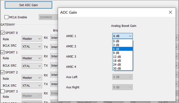
The figure shows how to configure ADC Gain.
ADC Gain
When configuring the Physical IO of a corresponding Physical MIC or AUX, also configure the ADC Gain of that Physical MIC or AUX. For example, if the Voice Primary In is configured in the Voice Category and Amic1 Differential is selected, then the ADC Gain value of Amic1 Differential should be configured.
After clicking the Set ADC Gain button, the ADC Gain configuration box will appear. Select the for Amic1 Differential from the drop-down box. The analog boost gain of the physical MIC or AUX can be set to values ranging from 0dB to 30dB in increments of 3dB.
Note
MIC
ADC Gaincan be adjusted using the Set ADC Gain button only ifAmicis selected.AUX
ADC Gaincan be adjusted by setting the Set ADC Gain button only whenAUXis selected.DmicGain cannot be adjusted by the Set ADC Gain button.Configure
ADC Gainfor theAmicindex as required.
Gateway
In the current Gateway parameters, the SPORT and SPDIF hardware parameters are configured by default. Unless there are specific requirements, there is no need to set the SPORT and SPDIF hardware parameters. If customers require the configuration of the SPORT and SPDIF parameters, they should contact the relevant developer to obtain and provide the necessary parameters. The default configuration for SPORT and SPDIF may vary depending on the specific IC.
The figure shows how to configure Gateway parameters.
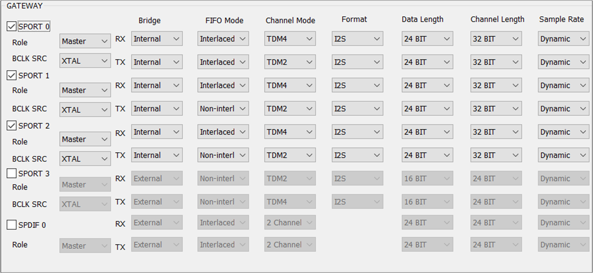
Gateway
Note
SPORT: Select this option to enable the SPORT of the corresponding index. The optional value is
SPORT0/1/2/3. If the Gateway index of an Audio Route path is selected, enable this Gateway index and configure related parameters. The figure shows when to configure Gateway index parameters.
SPDIF: Select this option to enable the SPDIF of the corresponding index. The optional value is
SPDIF0.Bridge: SPORT supports single-direction
TXandRXconfigurations. The options areInternalandExternal. It is worth noting that when this option is configured asExternal, go to the HW Feature tab to configure the corresponding PINMUX.Role: Configure the Role. The value can be
Masterorslave.BCLK SRC: Configure the BCLK and jitter functions. The optional value is
XTALorPLL.RX/TX FIFO Mode: Configure the manner in which the
RXandTXdirections of SPORT align FIFO data. The optional value isNon-interlacedorInterlaced.RX/TX Channel Mode: Configure the transfer mode in the
RXandTXdirections. The value isTDM2/4/6/8.RX/TX Format: Configure the format of SPORT data in the
RXandTXdirections. The value can beI2S/Left Justified/PCM_A/PCM_B.RX/TX Data Length: Configure the data length in the
RXandTXdirections of SPORT. The value is8/16/20/24/32BIT.RX/TX Channel Length: Configure the length of the channel in the
RXandTXdirections. The optional value is16/20/24/32BIT.RX/TX Sample Rate: Configure the
RXandTXdirection of SPORT support sampling rate conversion, optional value of8/16/32/44.1/48/88.2/96/192/12/24/11.025/22.05KHZ.
External Device
The figures show how to configure .
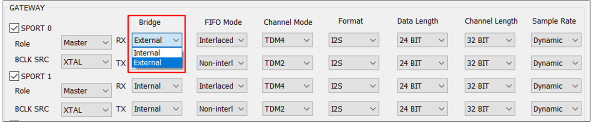
External Bridge
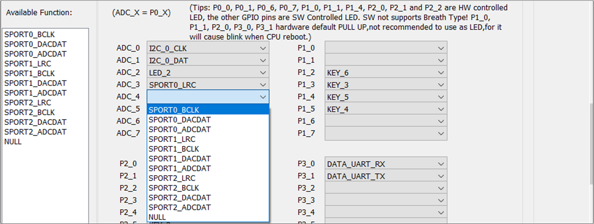
External Bridge PINMUX
To configure an external device in one direction, use the TX and RX drop-down boxes. For example, if the RX and TX options in the field of SPORT0 are configured as External, configure the corresponding PINMUX settings for SPORT0_LRC, SPORT0_BCLK, SPORT0_DACDAT, and SPORT0_ADCDAT in the HW Feature tab.
Note
When the field is set to
Master, theTXandRXfield allows users to freely selectExternalorInternal. When is set toSlave, theTXandRXof the field can only be changed to the fixed valueExternal.RTL87x3E and RTL87x3EP: For
SPORT0/1, you can configure the field based on the field. ForSPORT2, theTXandRXof its field is a fixed valueExternal, regardless of its value.RTL87x3D: For
SPORT0/1/2, you can configure the field based on the field. ForSPORT3, theTXandRXof its field is a fixed valueExternal, regardless of its value.
MCLK
The figure shows how to configure MCLK.
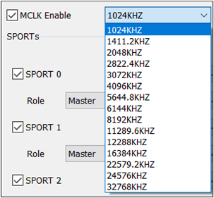
MCLK
MCLK is primarily used to configure the sample rate of the external DSP. Once the TX and RX options
in the field are configured as External, the frequency configuration will only take
effect when MCLK Enable is selected.
Note
If the MCLK Enable option is selected, external MCLK configuration is enabled.
With the MCLK Enable option checked, the optional is
1024KHZ,1411.2KHZ,2048KHZ,2822.4KHZ,3072KHZ,4096KHZ,5644.8KHZ,6144KHZ,8192KHZ,11289.6KHZ,12288KHZ,16384KHZ,22579.2KHZ,24576KHZ,32768KHZ.
BCLK
The figure shows how to configure BCLK.
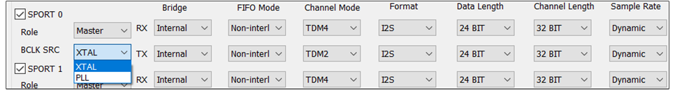
BCLK
If there is no special requirement, the XTAL crystal oscillator is used as the default clock source.
You can also choose PLL as the clock source by selecting the desired option from the
drop-down box.
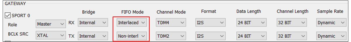
FIFO Mode
The is configured by default based on the specific product modality. If you need to
configure the of TX and RX, the available options are Interlaced or Non-interlaced.
The figure shows the different configurations of between TWS and Headset.
TWS
FIFO Mode of TWS
Headset

FIFO Mode of Headset
Channel Mode
The is configured by default. If you need to configure the fields of TX and RX in
GATEWAY, the available options include TDM2/4/6/8.
Note
For RTL87x3E and RTL87x3EP,
RXdefault value isTDM4,TXdefault value isTDM2.For RTL87x3D,
RXdefault value isTDM6,TXdefault value isTDM2.The index of must be smaller than the index. For example, when is
TDM4, you can only set toChannel0/1/2/3. The figure shows the limitation between and .
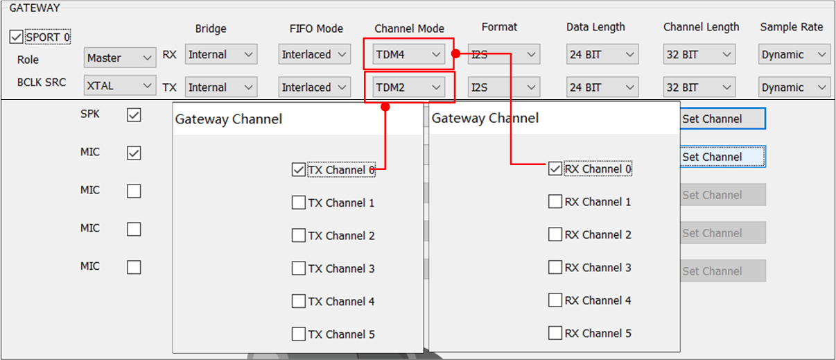
Limitation of Channel Mode and Gateway Channel
Data Length
The figure shows how to configure Gateway .
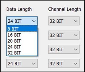
Gateway Data Length
The Gateway is configured by default. However, if there is a special requirement, it may be necessary to configure the fields of TX and RX in the Gateway.
Note
For RTL87x3E, RTL87x3EP and RTL87x3D: Set the to 24BIT.
Channel Length
The figure shows how to configure Gateway .
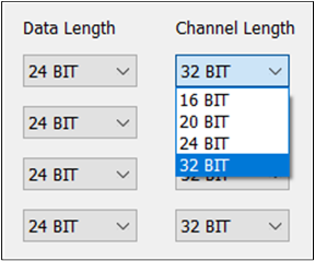
Gateway Channel Length
The Gateway is configured by default. However, if there is a special requirement, it may be necessary to configure the fields of TX and RX in the Gateway.
Note
For RTL87x3E, RTL87x3EP and RTL87x3D: Set the to 24BIT and the to 32BIT.
Sample Rate
The figure shows how to configure Gateway .
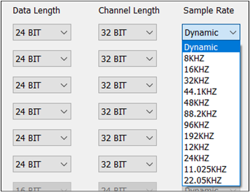
Gateway Sample Rate
The Gateway is configured by default. If there are special requirements, the TX and RX fields need to be configured in the GATEWAY. When selecting Dynamic for the , the physical data flow uses its own Sample Rate. On the other hand, selecting any other option indicates that the physical data path uses a fixed Sample Rate.
Note
When the Gateway is External, the Gateway should be set to fixed 48K.
Codec Mixing
Codec provides two mix data nodes, which can ignore the influence of sample rate and simultaneously play mixed data of two or three channels.
The figure shows a sample of Codec Mixing function.
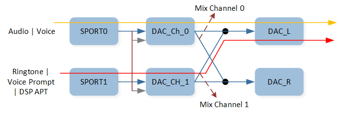
Codec Mixing Function
As shown in the figure, Audio or Voice and Voice Prompt are mixed, deployed, and played on DAC0. For tool
configuration, Codec mix supports the configuration of DAC0 and DAC1 to select the mix path of
the demand. This field is also configured by default.
The figure shows how to configure Codec Mixing function.

Codec Mixing
Note
If the
DAC1check box is selected inDAC0, it allows for the mixing of data fromDAC1toDAC0.Enabling the
DAC0check box inDAC1allows for the mixing of data fromDAC0toDAC1.
Codec Interpolation Filter
When there is a requirement to reduce the latency of the DAC Channel, Codec Interpolation Filter Type should be configured.
The figure shows how to configure Codec Interpolation Filter Type.
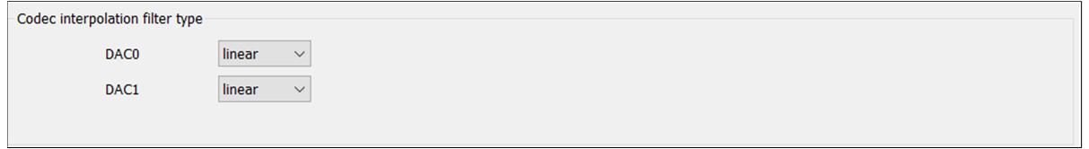
Codec Interpolation Filter Type
Each Codec DAC channel can choose either linear or minimum interpolation filter type.
Audio Logical Device
Audio Logic Device supports the configuration of Logic IO parameters for data streams such as Audio, Voice, Record, Line, Ringtone, Voice Prompt, APT, LLAPT, ANC and VAD. The Logical IO configuration of each category is different for TWS and Headset.
The figure shows how to configure the Audio Route path for different Audio Categories.
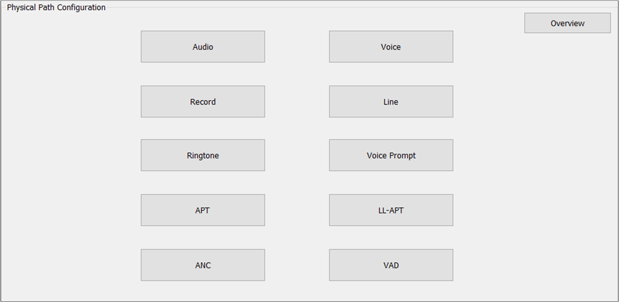
Audio Route Path of Audio Categories
If there is a need to configure the Logical IO parameter for the Audio Category, the appropriate Audio Category button should be clicked. The corresponding configuration box will then pop up. It should be noted that the Logical IO configuration is different for different product forms. This section explains how to configure Logical IO in terms of TWS and Headset. The Overview button can be clicked to get an overview of Logical IO configuration information for all Audio Categories.
Audio
Audio Category supports Audio Primary Out, Audio Secondary Out, Audio Primary Reference Out and Audio Secondary Reference Out.
Audio Primary Out is used to set the Audio physical route of the Primary output.
Audio Secondary Out is used to set the Audio physical route of the Secondary output.
Audio Primary Reference Out is used to set the Audio physical AEC loopback path of the Primary output.
Audio Secondary Reference Out is used to set the Audio physical AEC loopback path of the Secondary output.
TWS
The figure shows how to configure an Audio Route path for Audio Out of TWS.
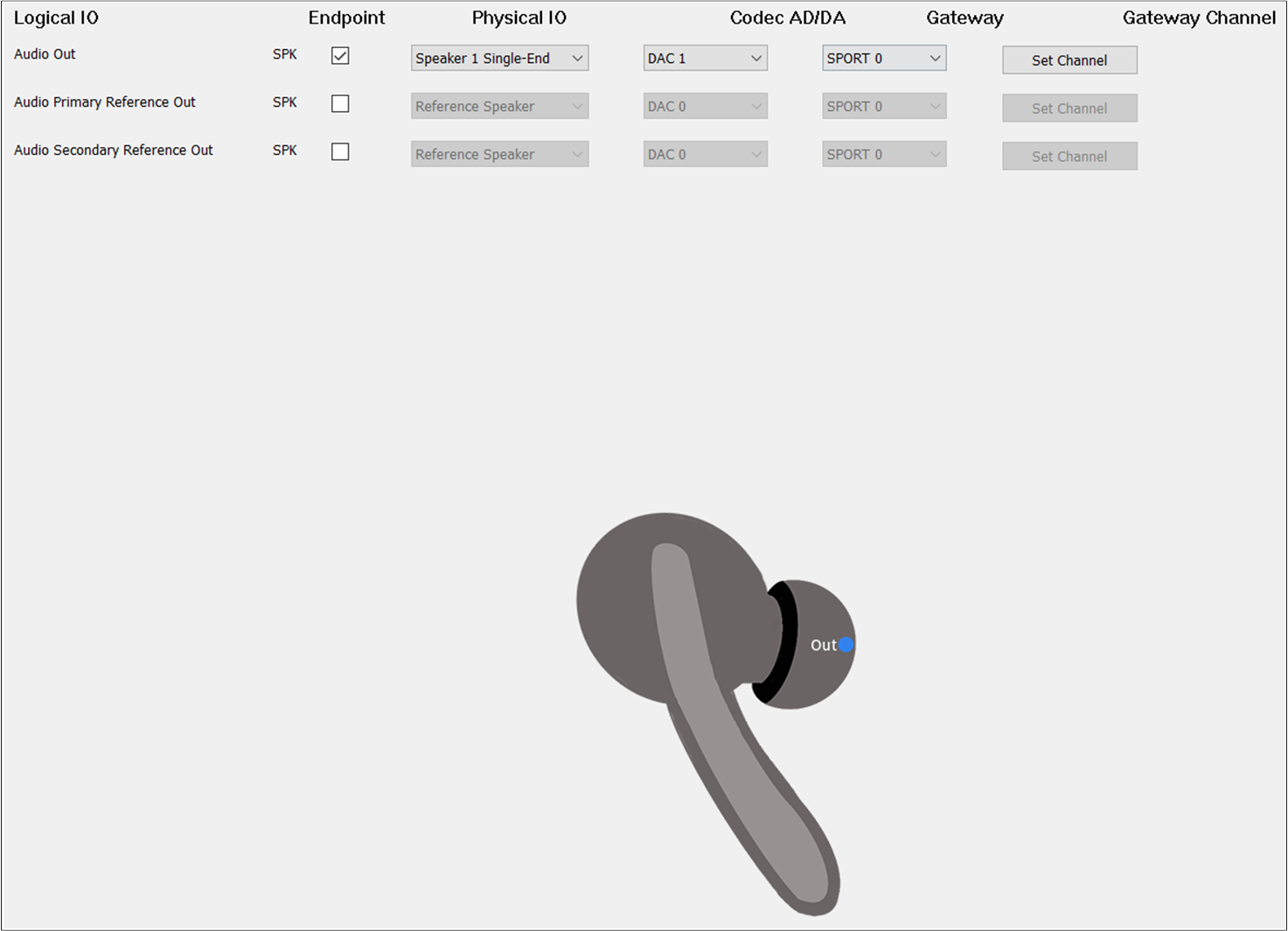
Audio Route of TWS
As shown in the figure, this line of configuration for Audio Out forms an Audio Route path. When
clicking the blue dot Out in the TWS headphone diagram, the Audio Out will be bolded to indicate that
it’s necessary to configure the Audio Route path in order to play the audio sound. Check the
box on the Endpoint to enable Audio Out. For Physical IO, select
Speaker1/2 Single-end/Differential. For Codec AD/DA, select DAC0. For Gateway, select SPORT0. For Gateway Channel, select TX Channel 0.
Headset
The figure shows how to configure Audio Route path for Audio Category of Headset.
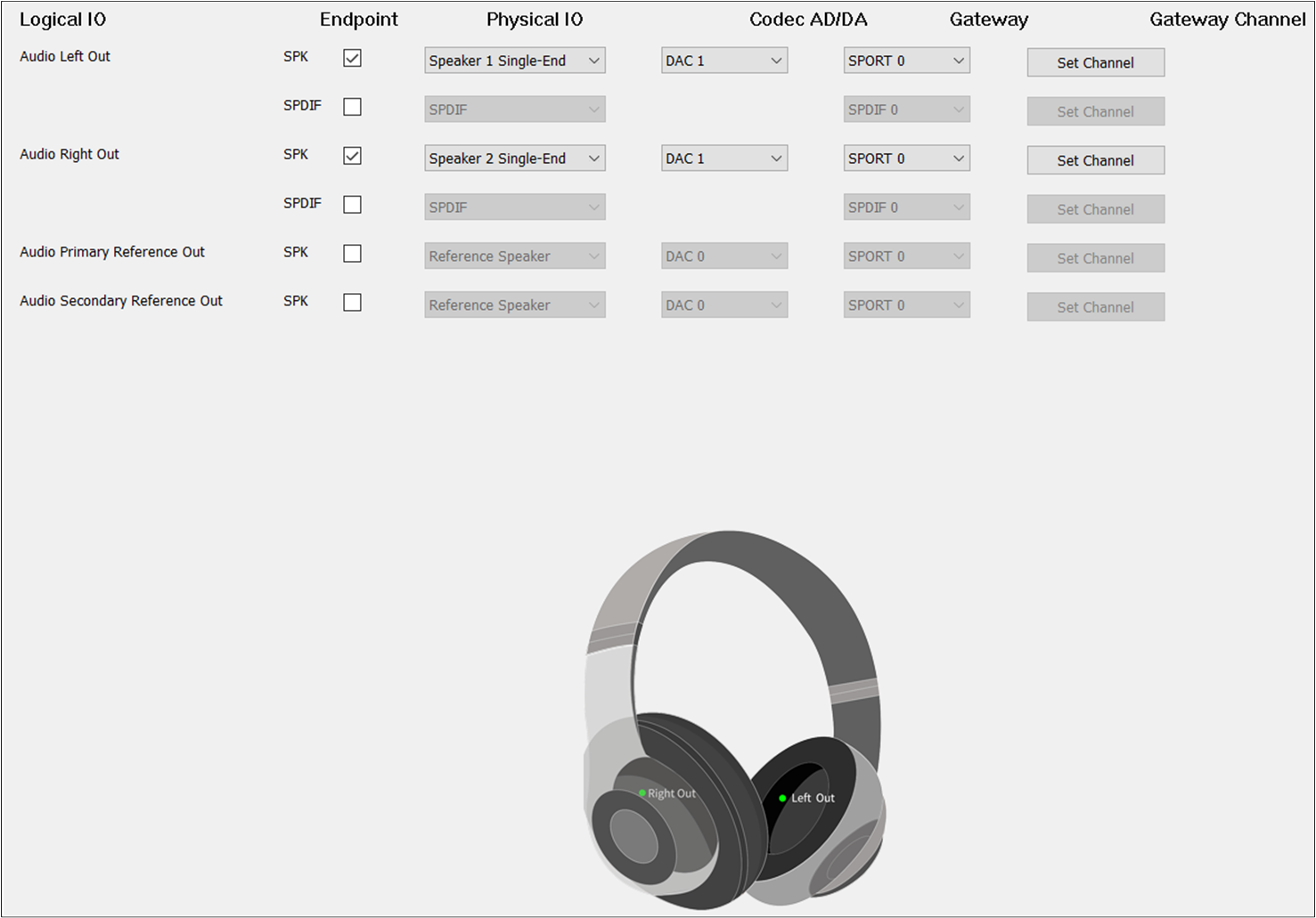
Audio Route of Headset
Different from TWS, Headset needs to select Audio Primary Out and Audio Secondary Out. For Audio
Secondary Out, the should be set to DAC1 and the should be set to TX
Channel 1.
AEC Loopback
AEC means linear removal of echo signal mixing in microphone input without affecting the
quality of the desired speech signal. To enable the AEC loopback function, check the Audio Primary Reference Out or Audio Secondary Reference Out. For Physical IO of Audio
Primary Reference Out and Audio Secondary Reference Out, select Reference Speaker.
Note
When the Record Primary Reference In and Record Secondary Reference In corresponding to the Record Category are also configured, the AEC loopback path of Audio and Record can be really connected.
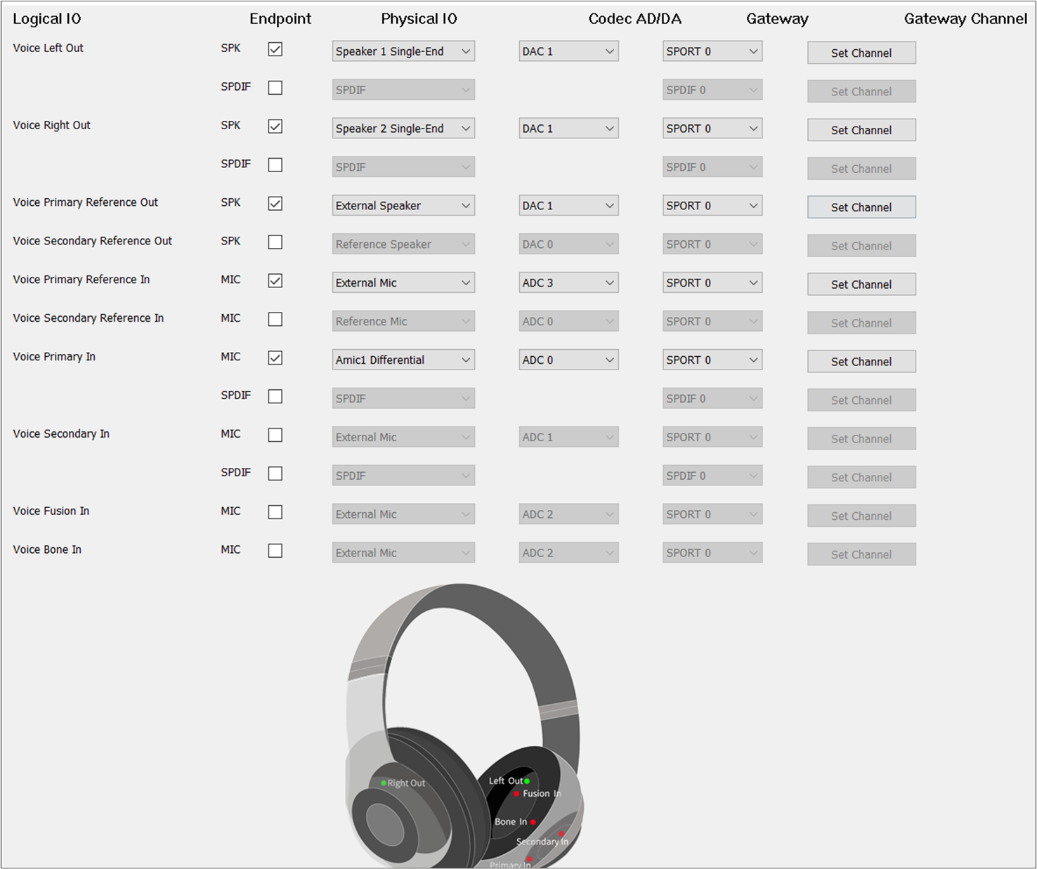
Voice
Voice Category supports Voice Primary Out, Voice Secondary Out, Voice Primary Reference Out, Voice Secondary Reference Out, Voice Primary Reference In, Voice Secondary Reference In, Voice Primary Reference In, Voice Primary In, Voice Secondary In, Voice Fusion In and Voice Bone In:
Voice Primary Out is used to set the Voice physical route of the Primary output Endpoint.
Voice Secondary Out is used to set the Voice physical route of the Secondary output Endpoint.
Voice Primary Reference Out is used to set the Voice physical AEC loopback path of the Primary output Endpoint.
Voice Secondary Reference Out is used to set the Voice physical AEC loopback path of the Secondary output Endpoint.
Voice Primary Reference In is used to set the Voice physical AEC loopback path of the Primary input Endpoint.
Voice Secondary Reference In is used to set the Voice physical AEC loopback path of the Secondary input Endpoint.
Voice Primary In is used to set the Voice physical route for the Primary input Endpoint.
Voice Secondary In is used to set the Voice physical route of the Secondary input Endpoint.
Voice Fusion In is used to set the Voice physical route for Fusion input Endpoint.
Voice Bone In is used to set the Voice physical route for the Bone Sensor input Endpoint.
TWS
The figure shows how to configure an Audio Route path for Voice Out of TWS.
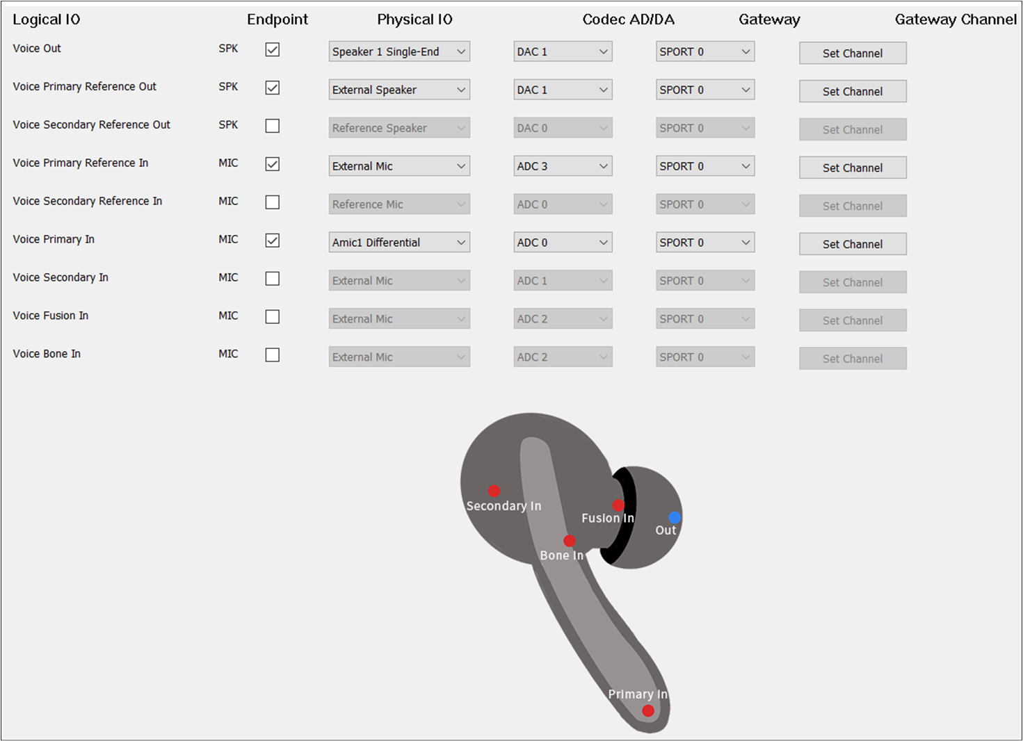
Voice Route of TWS
Voice Out should be selected. The Voice Out parameters are the same as the Audio Out parameters.
Headset
The figure shows how to configure an Audio Route path for the Voice Category of Headset.
Voice Route of Headset
Different from TWS, Headset needs to select Voice Primary Out and Voice Secondary Out. For Voice
Secondary Out, the should be set to DAC1 and the should be set to TX
Channel 1.
Default MIC
If there is no special requirement, the Voice Primary In should be selected to play the input voice.
For , check the MIC button to enable Voice Primary In. For , select the index and type of MIC. For ADC Channel, select ADC0/1/2/3/4/5. For Gateway, select SPORT0. For Gateway Channel, select RX Channel 0/1/2/3. It should be noted
that the and should choose a different index for different Logical IO.
Dual MIC
When two microphones are needed as input, select Voice Primary In and Voice Secondary In.
It should be noted that the and of Voice Primary In and Voice Secondary
In should be different. For example, when the of Voice Primary In is set to ADC0, the
of Voice Secondary In should be set to ADC1/2/3/4. The of Voice Primary
In is set to RX Channel 0, the of Voice Secondary In should be set to RX
Channel 1/2/3/4.
Audio Effect Requirements
When other voice sound effects requirements arise, Voice Fusion In and Voice
Bone In can be configured. Similarly, the and of Voice Fusion In and Voice Bone In should
be different from Voice Primary In and Voice Secondary In.
AEC Loopback
When there is a requirement for AEC loopback functionality, select the Voice Primary
Reference Out and Voice Primary Reference In at the same time. The Voice
Secondary Reference Out and Voice Secondary Reference In can also be selected at the same time to enable the AEC loopback
functionality. For of Voice Reference Primary Out and Voice Reference Secondary Out,
select Reference Speaker. For DAC Channel of Voice Reference Primary Out and Voice
Reference Secondary Out, select DAC0 or DAC1. For of Voice Reference Primary In
and Voice Reference Secondary In, select Reference MIC. It should be noted that the and should choose a different index for different Logical IO.
Note
When the Voice Primary Reference Out and Voice Primary Reference In corresponding to the Voice Category, or when the Voice Secondary Reference Out and Voice Secondary Reference In are configured, the AEC loopback path is actually connected.
Record
Record Category supports Record Primary In, Record Secondary In, Record Primary Reference In, Record Secondary Reference In, Record Fusion In, and Record Bone In:
Record Primary In is used to set the Record physical route of the Primary input Endpoint.
Record Secondary In is used to set the Record physical route of the Secondary input Endpoint
Record Primary Reference In is used to set the Record physical AEC loopback path of the Primary input Endpoint.
Record Secondary Reference In is used to set the Record physical AEC loopback path of the Secondary input Endpoint.
Record Fusion In is used to set the Record physical route of the Fusion input Endpoint.
Record Bone In is used to set the Record physical route of the Bone Sensor input Endpoint.
TWS
The figure shows how to configure an Audio Route path for Record In of TWS.
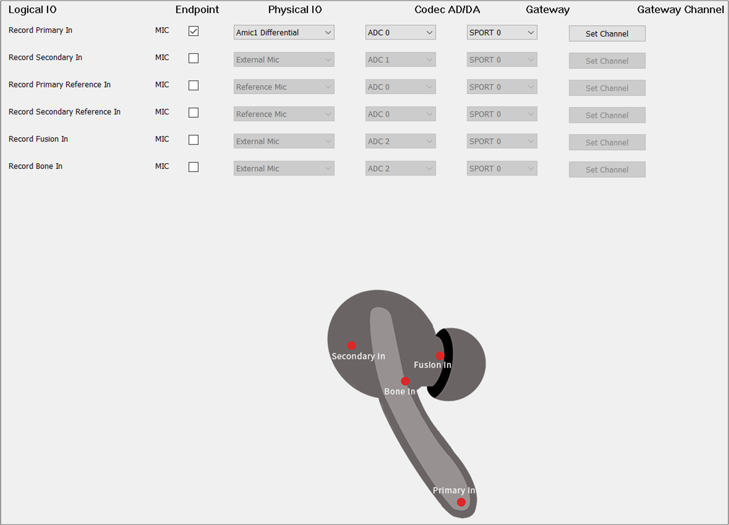
Record Route of TWS
Record Primary In should be selected. The Record Primary In parameters are the same as the
Voice Primary In.
Headset
The figure shows how to configure the Audio Route path for the Record Category of Headset.
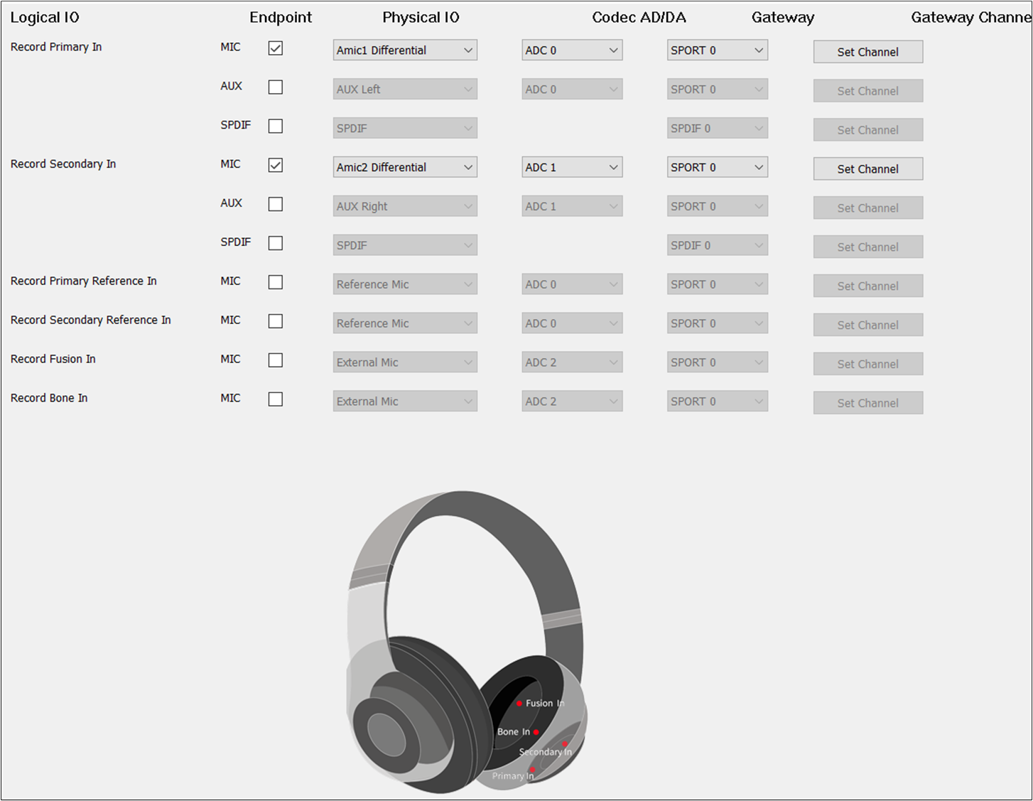
Record Route of Headset
Record Primary In and Record Secondary In should be selected.
Default MIC
If there is no special requirement, the Record Primary In should be selected to record the input
sound. For , check the MIC button to enable Record Primary In. For ,
select the index and type of MIC. For , select ADC0/1/2/3/4/5. For
Gateway, select SPORT0. For , select RX Channel 0/1/2/3. It should
be noted that the and should choose a different index for different
Logical IO.
Dual MIC
When two microphones are needed as input, check Record Primary In and Record Secondary In.
It should be noted that the and of Record Primary In and Record
Secondary In should be different.
Audio Effect Requirements
When other voice sound effects are required, configure Record Fusion In and Record
Bone In. The and of Record Fusion In and Record Bone In should also be
different from each other.
AEC Loopback
When the AEC loopback functionality is required, check the Audio Primary
Reference Out and Record Primary Reference In at the same time. Also, check the Audio
Secondary Reference Out and Record Secondary Reference In at the same time to enable the AEC
loopback functionality. The and of Record Primary Reference In and
Record Secondary Reference In should also be different from Record Primary In, Record Secondary In,
Record Fusion In and Record Bone In if they are selected.
Note
When the Audio Primary Reference Out and Audio Secondary Reference Out corresponding to Audio Category, Ringtone Category or Voice Prompt Category are configured, the AEC loopback path for Audio and Record, Ringtone and Record, or Voice Prompt and Record is open.
Line
Line Category supports Line Primary Out, Line Secondary Out, Line Primary Reference Out, Line Secondary Reference Out, Line Left In, Line Right In, Line Primary Reference In and Line Secondary Reference In:
Line Primary Out is used to set the Line physical route of the Primary output Endpoint.
Line Secondary Out is used to set the Line physical route of the Secondary output Endpoint.
Line Primary Reference Out is used to set the Line physical AEC loopback path of the Primary output Endpoint.
Line Secondary Reference Out is used to set the Line physical AEC loopback path of the Secondary output Endpoint.
Line Primary Reference In is used to set the Line physical AEC loopback path of the Primary input Endpoint.
Line Secondary Reference In is used to set the Line physical AEC loopback path of the Secondary input Endpoint.
Line Primary In is used to set the Line physical route of the Primary input Endpoint.
Line Secondary In is used to set the Line physical route of the Line Secondary input Endpoint.
TWS
The figure shows how to configure the Audio Route path for the Line Category of TWS.
Line Route of TWS
To play the sound of the Line and record the input of the Line, select Line Out and Line In.
For the of Line, select AUX, and the should be set to AUX Left.
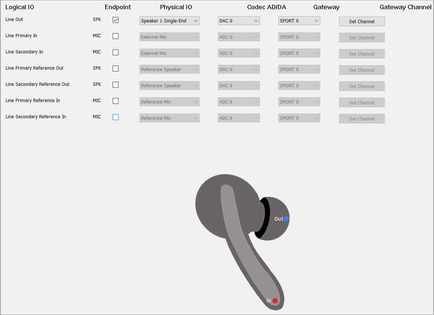
Headset
The figure shows how to configure the Audio Route path for the Line Category of Headset.
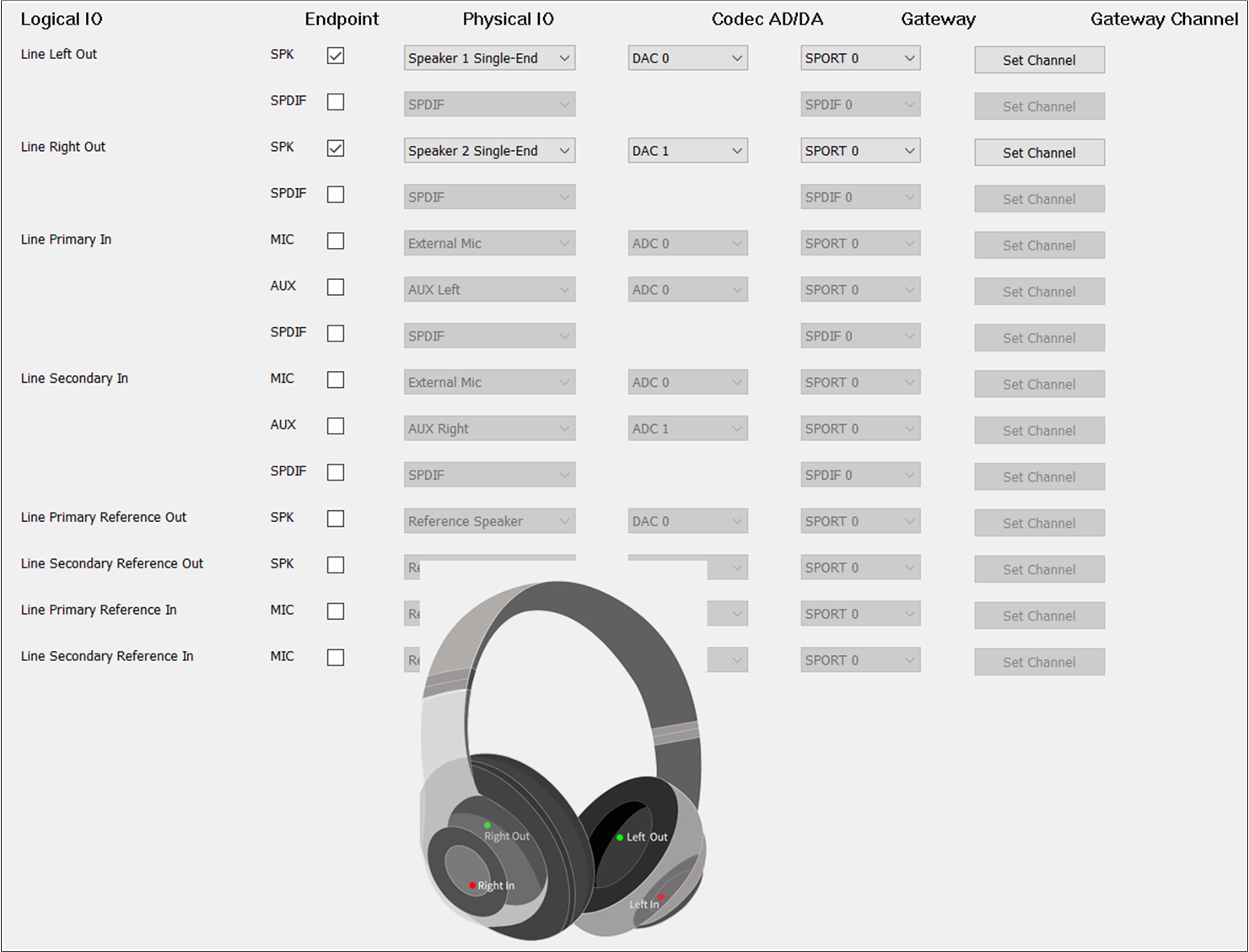
Line Route of Headset
For Headset, select Line Primary Out and Line Secondary Out, Line Left In and Line Right
In. The and of Line Primary Out and Line Secondary Out are the same as
Audio Primary Out and Audio Secondary Out. The and of Line Left In and
Line Right In should be different.
AEC Loopback
When there is a requirement for AEC loopback functionality, check the Line Primary
Reference Out and Line Primary Reference In at the same time. Also, check the Line Secondary
Reference Out and Line Secondary Reference In at the same time to enable the AEC loopback
functionality. The and of Line Primary Reference In and Line Secondary
Reference In should also be different from Line Left In, Line Right In if they are selected.
Note
When the Line Primary Reference Out and Line Primary Reference In corresponding to the Line Category, or when the Line Secondary Reference Out and Line Secondary Reference In are configured, the loopback path of the AEC is actually connected.
Ringtone
Ringtone Category supports Ringtone Primary Out, Ringtone Secondary Out, Ringtone Primary Reference Out and Ringtone Secondary Reference Out:
Ringtone Primary Out is used to set the Ringtone physical route of the Primary output Endpoint.
Ringtone Secondary Out is used to set the Ringtone physical route of the Secondary output Endpoint.
Ringtone Primary Reference Out is used to set the Ringtone physical AEC loopback path of the Primary output Endpoint.
Ringtone Secondary Reference Out is used to set the Ringtone physical AEC loopback path of the Secondary output Endpoint.
TWS
The figure shows how to configure an Audio Route path for Ringtone Out of TWS.
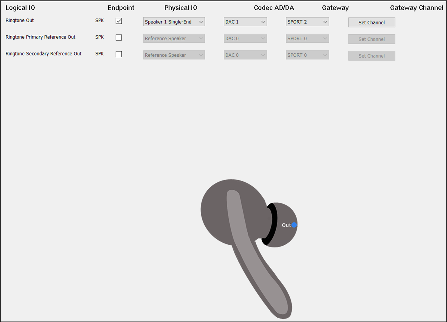
Ringtone Route of TWS
Check the box on the Endpoint to enable Ringtone Out. For , select
Speaker1/2 Single-end/Differential. For , select DAC2. For , select SPORT2. For , select TX Channel 0.
Headset
The figure shows how to configure the Audio Route path for the Ringtone Category of Headset.
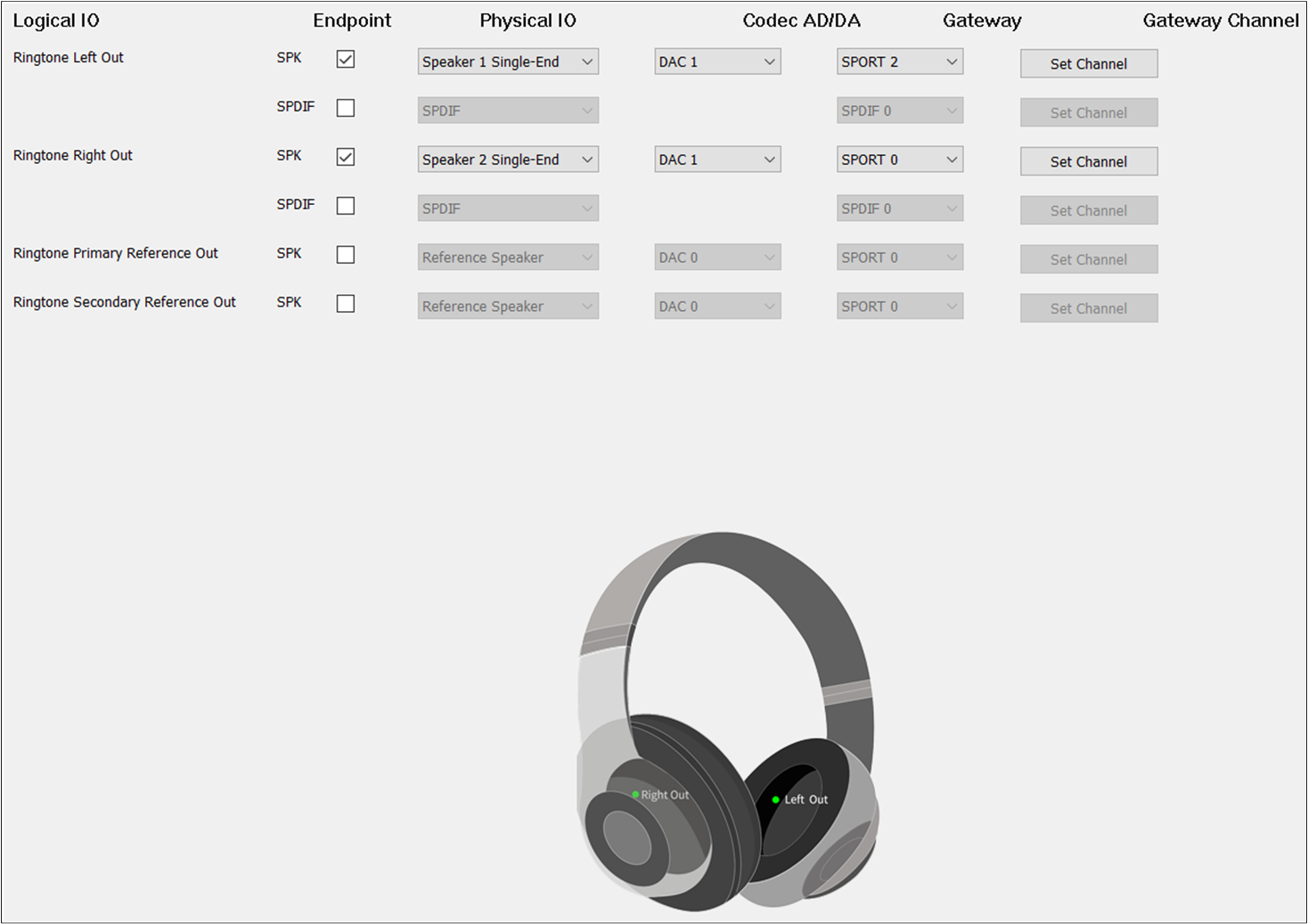
Ringtone Route of Headset
Different from TWS, Headset needs to check Ringtone Primary Out and Ringtone Secondary Out. For
Ringtone Secondary Out, the should be set to DAC1 and the should be set
to TX Channel 1.
AEC Loopback
To enable the AEC loopback function, check the Ringtone Primary Reference
Out or Ringtone Secondary Reference Out.
Note
When the Record Primary Reference In and Record Secondary Reference In corresponding to the Record Category are also configured, the AEC loopback path of Ringtone and Record is really open.
Voice Prompt
Voice Prompt Category supports Voice Prompt Primary Out, Voice Prompt Secondary Out, Voice Prompt Primary Reference Out and Voice Prompt Secondary Reference Out:
Voice Prompt Primary Out is used to set the Voice Prompt physical route path of the Primary output Endpoint.
Voice Prompt Secondary Out is used to set the Voice Prompt physical route path of the Secondary output Endpoint.
Voice Prompt Primary Reference Out is used to set the physical AEC loopback path of the Voice Prompt in the Primary output Endpoint.
Voice Prompt Secondary Reference Out is used to set the physical AEC loopback path of the Voice Prompt of the Secondary output Endpoint.
TWS
The figure shows how to configure an Audio Route path for Voice Prompt Out of TWS.
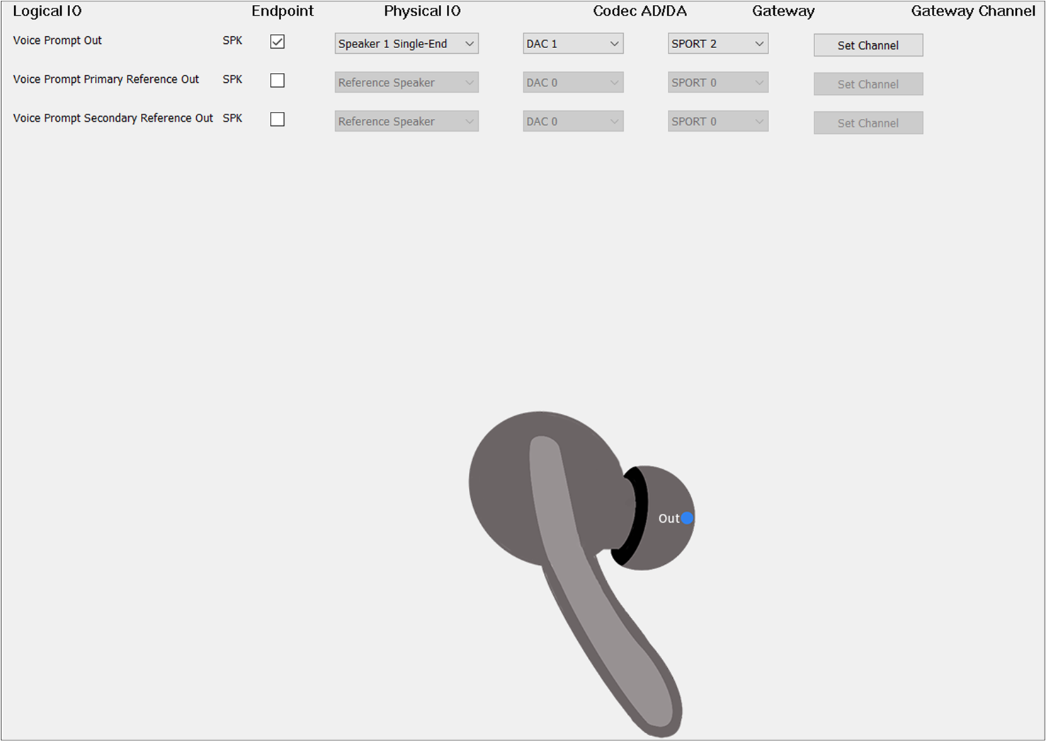
Voice Prompt Route of TWS
The box on the should be checked to enable Voice Prompt Out. For , select
Speaker1/2 Single-end/Differential. For , select DAC2. For , select SPORT2. For , select TX Channel 0.
Headset
The figure shows how to configure the Audio Route path for the Voice Prompt Category of Headset.
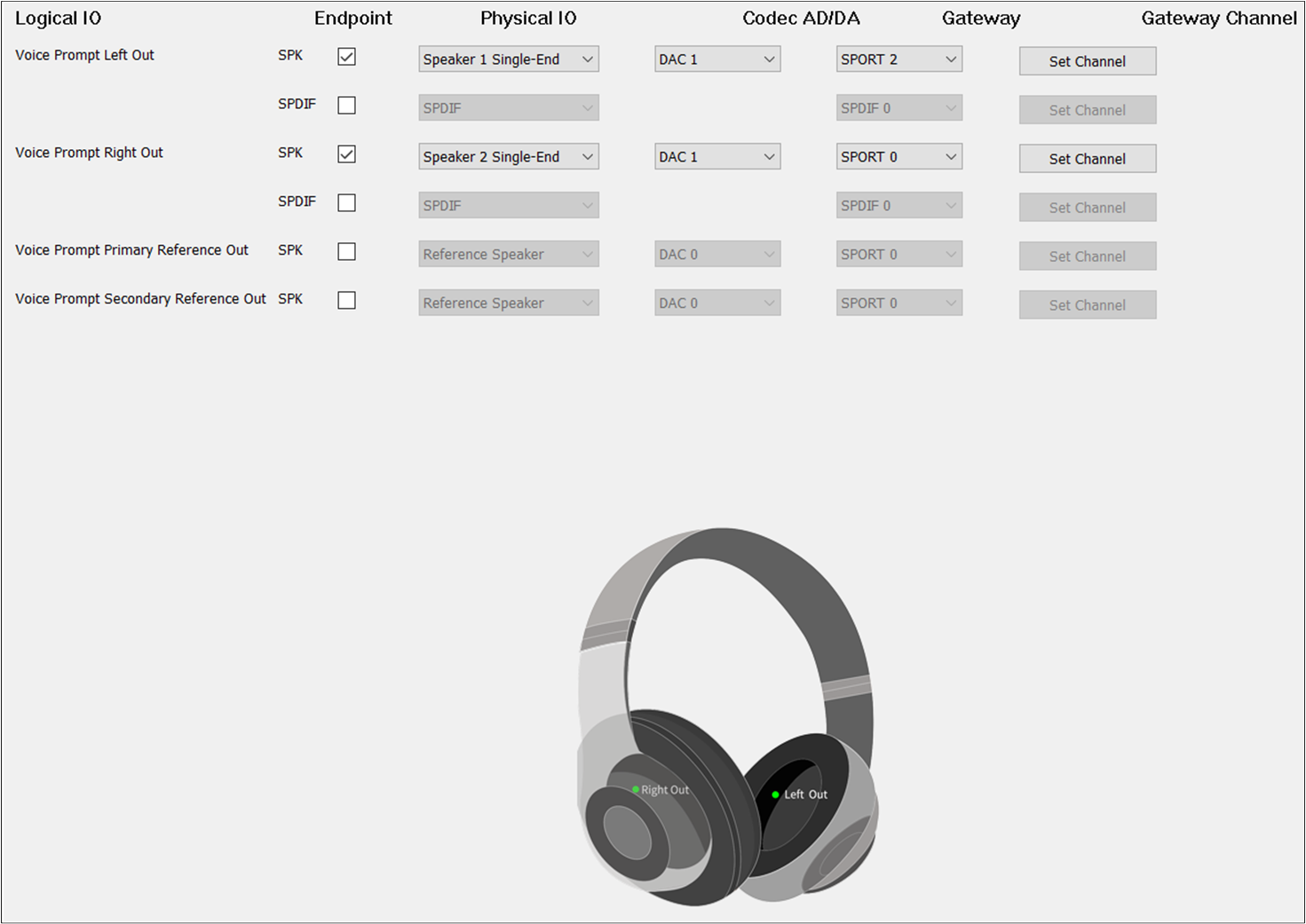
Voice Prompt Route of Headset
Different from TWS, Headset needs to check Voice Prompt Primary Out and Voice Prompt Secondary Out.
For Voice Prompt Secondary Out, set the to DAC1 and the to TX Channel 1.
AEC Loopback
To enable the AEC loopback function, check the Voice Prompt Primary Reference
Out or Voice Prompt Secondary Reference Out.
Note
When the Record Primary Reference In and Record Secondary Reference In corresponding to the Record Category are also configured, the AEC loopback path of the Voice Prompt and the Record is really open.
ANC
ANC Category supports ANC Primary Out, ANC Secondary Out, ANC Primary Reference Out, ANC Secondary Reference Out, ANC Secondary Reference Out, ANC Primary Reference In, ANC Secondary Reference In, ANC FF Left In, ANC FF Right In, ANC FB Left In and ANC FB Right In:
ANC Primary Out is used to set the ANC physical route of the Primary output Endpoint.
ANC Secondary Out is used to set the ANC physical route of the Secondary output Endpoint.
ANC Primary Reference Out is used to set the ANC physical AEC loopback path of the Primary output Endpoint.
ANC Secondary Reference Out is used to set the ANC physical AEC loopback path of the Secondary output Endpoint.
ANC Primary Reference In is used to set the ANC physical AEC loopback path of the Primary input Endpoint.
ANC Secondary Reference In is used to set the ANC physical AEC loopback path of the Secondary input Endpoint.
ANC FF Left In is used to set the ANC physical route with the Feedforward Left input Endpoint.
ANC FF Right In is used to set the ANC physical route with the Feedforward Right input Endpoint.
ANC FB Left In is used to set the ANC physical route of the Feedback Left input Endpoint.
ANC FB Right In is used to set the ANC physical route of the Feedback Right input Endpoint.
TWS
The figure shows how to configure an Audio Route path for ANC of TWS.
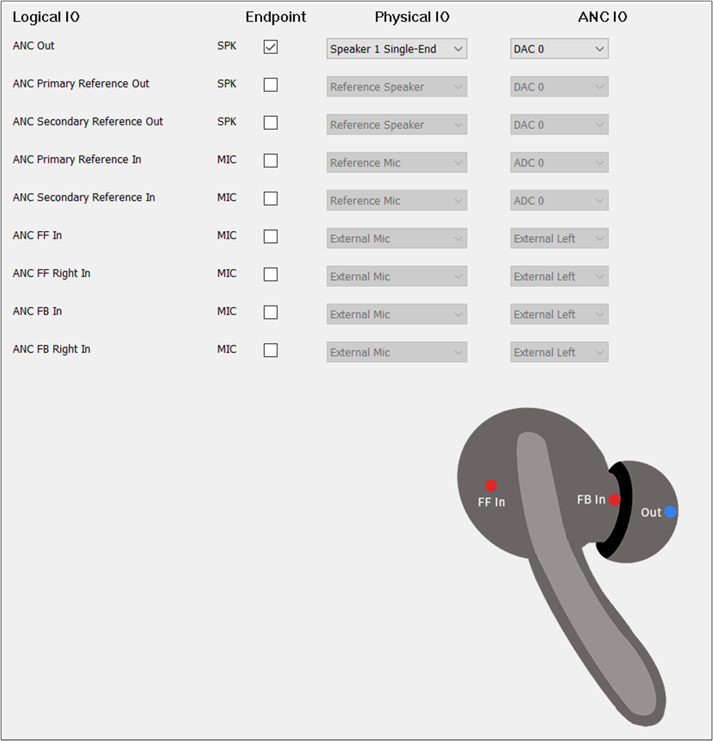
ANC Route of TWS
To play the sound of ANC, select the ANC Out. The configuration of ANC Out could be the same as Audio Out. To record the input sound of ANC, there are three scenarios. Configure it according to requirements. Only select ANC FF In. Only select ANC FB In. Select ANC FF In and ANC FB In together. For the ANC IO of ANC, select External Left, External Right, Internal Left, and Internal Right. But for ANC FF In, the must be set to External Left for TWS. For ANC FB IN, the must be set to Internal Right.
Headset
ANC Primary Out and ANC Secondary Out should be checked.
The figure shows how to configure the Audio Route path for the ANC Category of Headset.
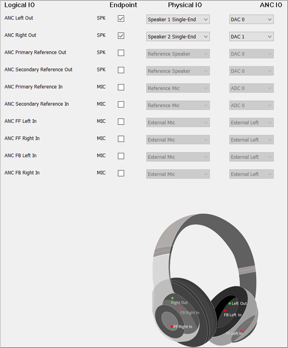
ANC Route of Headset
The and of ANC Primary Out and ANC Secondary Out are the same as Audio
Primary Out and Audio Secondary Out. ANC FF Left In and ANC FF Right In should be selected. ANC FB
Left In and ANC FB Right In should be selected. The and of ANC Left In must
be different from ANC Right In. The of ANC FF Left In must be set to External Left. of ANC FF Right In must be set to External Right. The of ANC FB Left In must be set to
Internal Left. The of ANC FB Right In must be set to Internal Right.
AEC Loopback
When enabling the AEC loopback function, check the ANC Primary Reference Out and ANC Primary Reference In. It is also possible to select ANC Secondary Reference Out and ANC Secondary Reference In.
Note
When ANC Primary Reference Out and ANC Primary Reference In correspond to ANC Category, or when the ANC Secondary Reference Out and ANC Secondary Reference In are well configured, the AEC loopback path can be really opened.
APT
APT function supports APT Primary Out, APT Secondary Out, APT Primary Reference Out, APT Secondary Reference Out, APT Primary Reference In, APT Secondary Reference In, APT Front Left In, APT Front Right In, APT FF Left In and APT FF Right In, APT FB Left In, APT FB Right In, APT Bone Left In and APT Bone Right In:
APT Primary Out is used to set the APT physical route of the Primary output Endpoint.
APT Secondary Out is used to set the APT physical route of the Secondary output Endpoint.
APT Primary Reference Out is used to set the APT physical AEC loopback path of the Primary output Endpoint.
APT Secondary Reference Out is used to set the APT physical AEC loopback path of the Secondary output Endpoint.
APT Primary Reference In is used to set the APT physical AEC loopback channel of the Primary input Endpoint.
APT Secondary Reference In is used to set the APT physical AEC loopback channel of the Secondary input Endpoint.
APT Front Left In is used to set the APT physical route of the front Left input Endpoint.
APT Front Right In is used to set the APT physical route of the front Right input Endpoint.
APT FF Left In is used to set the APT physical route of the FF Left input Endpoint.
APT FF Right In is used to set the APT physical route of the FF Right input Endpoint.
APT FB Left In is used to set the APT physical route of the FB Left input Endpoint.
APT FB Right In is used to set the APT physical route of the FB Right input Endpoint.
APT Bone Left In is used to set the APT physical route of the Bone Sensor Left input Endpoint.
APT Bone Right In is used to set the APT physical route of the Bone Sensor Right input Endpoint.
TWS
The figure shows how to configure an Audio Route path for APT of TWS.
APT Route of TWS
To play the sound of APT, select the APT Out. For , select Speaker1/2 Single-end/Differential. For , select DAC1. For , select
SPORT1. For , select TX Channel 0.
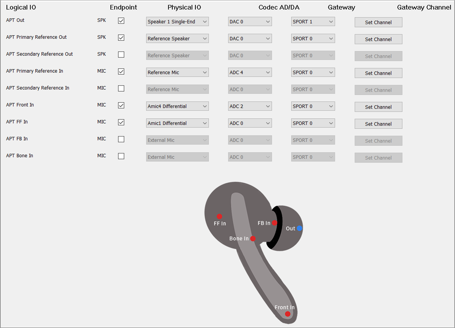
Headset
APT Primary Out and APT Secondary Out should be selected.
The figure shows how to configure the Audio Route path for the APT Category of Headset.
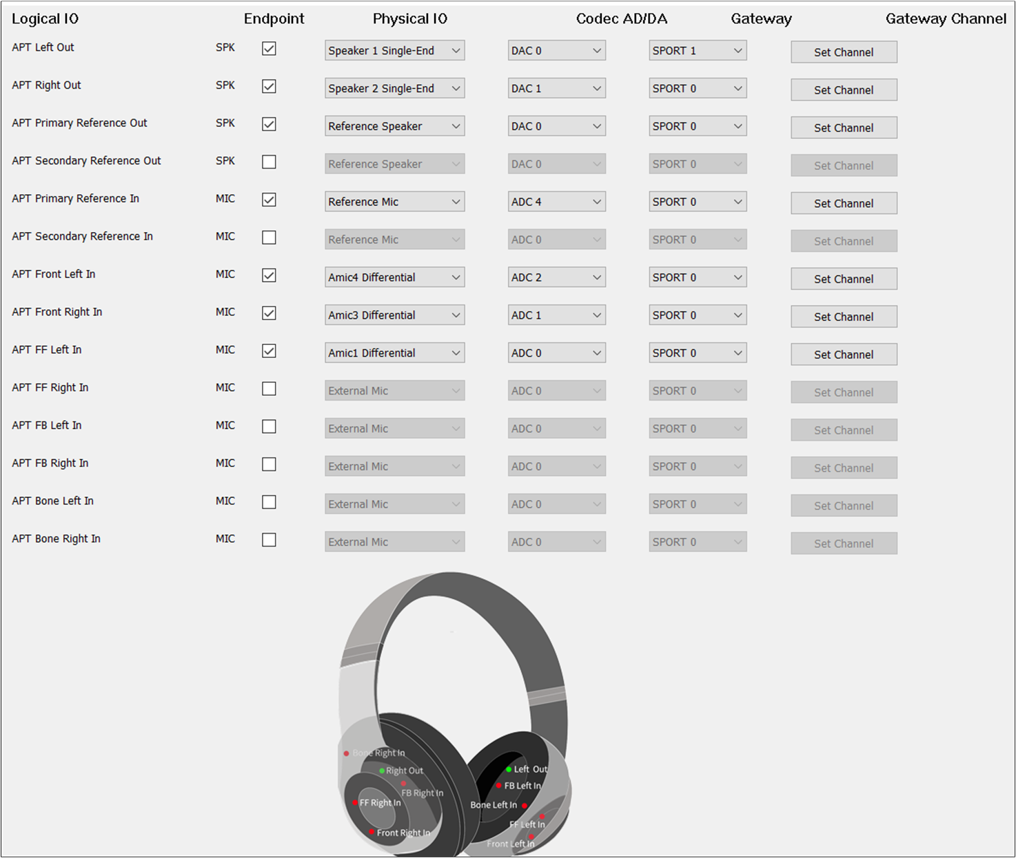
APT Route of Headset
The and of APT Primary Out and APT Secondary Out are the same as Audio
Primary Out and Audio Secondary Out.
Default MIC
If there is no special requirement, the APT Front In should be selected to record the input sound of
APT. For , check the MIC button to enable APT Front In. For , select the index and type of mic. For , select ADC0/1/2/3/4/5. For , select SPORT0. For , select RX Channel 0/1/2/3.
Dual MIC
When two microphones are needed as input, check APT Front In and APT FF In for TWS. For
Headset, select two of APT Front Left In, APT Front Right In, APT FF Left In, APT FF Right
In, APT FB Left In, and APT FB Right In. Note that the and
of APT Front In and APT FF In should be different.
Three MIC Requirements
When three microphones are needed as input, check APT Front In, APT FF In, and APT FB In for TWS.
For Headset, select three of APT Front Left In, APT Front Right In, APT FF Left In, APT FF
Right In, APT FB Left In, and APT FB Right In. The and of APT Front In,
APT FF In, and APT FB In should also be different from each other.
Audio Effect Requirements
When other voice sound effects are needed, configure APT Bone In for TWS. For
Headset, select APT Bone Left In or APT Bone Right In. The and
of APT Bone In should also be different from APT Front In, APT FF In, and APT FB In.
AEC Loopback
To enable the AEC loopback function, check the APT Primary Reference Out
and APT Primary Reference In. Select APT Secondary Reference Out and APT Secondary
Reference In.
Note
When APT Primary Reference Out and APT Primary Reference In correspond to APT Category, or when APT Secondary Reference Out and APT Secondary Reference In are configured, the AEC loopback path can be really opened.
LLAPT
LL-APT function supports LL-APT Primary Out, LL-APT Secondary Out, LL-APT Primary Reference Out, LL-APT Secondary Reference Out, LL-APT Primary Reference In, LL-APT Secondary Reference In, LL-APT Left In, and LL-APT Right In:
LL-APT Primary Out is used to set the LL-APT physical route of the Primary output Endpoint.
LL-APT Secondary Out is used to set the LL-APT physical route of the Secondary output Endpoint.
LL-APT Primary Reference Out is used to set the LL-APT physical AEC loopback path of the Primary output Endpoint.
LL-APT Secondary Reference Out is used to set the LL-APT physical AEC loopback path of the Secondary output Endpoint.
LL-APT Primary Reference In is used to set the LL-APT physical AEC loopback path of the Primary input Endpoint.
LL-APT Secondary Reference In is used to set the LL-APT physical AEC loopback path of the Secondary input Endpoint.
LL-APT Left In is used to set the LL-APT physical route of the Left input Endpoint.
LL-APT Right In is used to set the LL-APT physical route of the Right input Endpoint.
TWS
The figure shows how to configure an Audio Route path for LLAPT of TWS.
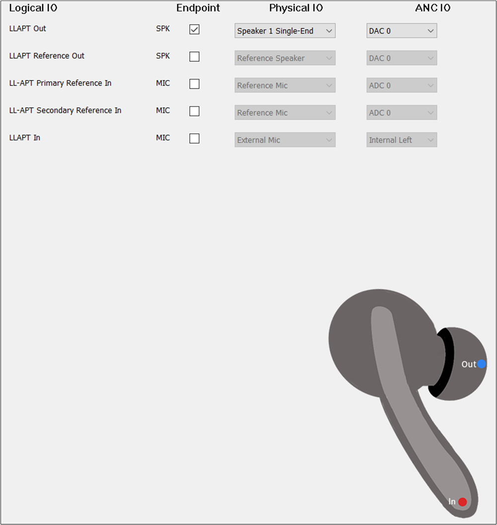
LLAPT Route of TWS
To play the sound of LLAPT, select the LLAPT Out. The configuration of LLAPT Out could be
the same as Audio Out. To record the input sound of LLAPT, select the LLAPT In. For the
of LLAPT In, select External Left, External Right, Internal Left, and Internal Right.
But for LLAPT In, the must be set to External Right for TWS.
Headset
LLAPT Primary Out and LLAPT Secondary Out should be checked.
The figure shows how to configure Audio Route path for LLAPT Category of Headset.
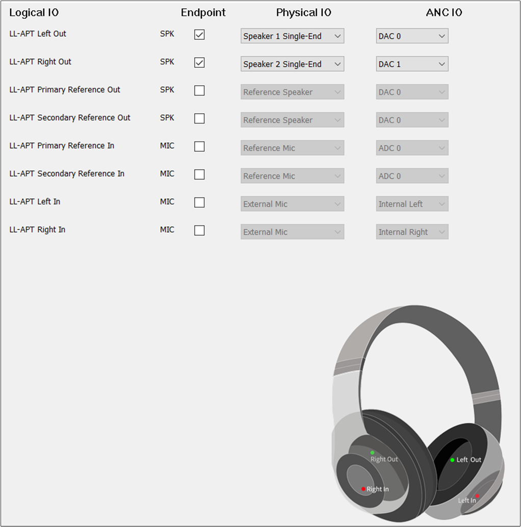
LLAPT Route of Headset
The and of LLAPT Primary Out and LLAPT Secondary Out are the same as
Audio
Primary Out
and Audio Secondary Out. LLAPT Left In and LLAPT Right In should be selected.
The and of LLAPT Left In must be different from LLAPT Right In. The of
LLAPT Left IN must be set to External Left. The of LLAPT Right IN must be set to External Right.
AEC Loopback
To enable the AEC loopback function, check the LLAPT Primary Reference Out
and LLAPT Primary Reference In. Select LLAPT Secondary Reference Out and LLAPT
Secondary Reference In.
Note
When LL-APT Primary Reference Out and LL-APT Primary Reference In correspond to LL-APT Category, or when the LL-APT Secondary Reference Out and LL-APT Secondary Reference In are configured, the AEC loopback path can be really connected.
VAD
VAD Category supports VAD Primary In, VAD Secondary In, VAD Primary Reference In, VAD Secondary Reference In:
VAD Primary In is used to set the VAD physical route of the Primary input Endpoint.
VAD
Secondary
In is used to set the VAD physical route of the Secondary input Endpoint.
VAD Primary Reference In is used to set the VAD physical AEC loopback path of the Primary input Endpoint.
VAD Secondary Reference In is used to set the VAD physical AEC loopback path of the Secondary input Endpoint.
TWS
The figure shows how to configure an Audio Route path for VAD In of TWS.

VAD Route of TWS
VAD Primary In should be selected. The VAD Primary In parameters are the same as the Record Primary In.
Headset
The figure shows how to configure the Audio Route path for the VAD Category of Headset.
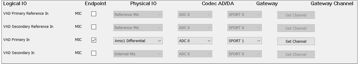
VAD Route of Headset
VAD Primary In and VAD Secondary In should be selected
Default MIC
If there is no special requirement, the VAD Primary In should be selected to record the input
sound. For , check the MIC button to enable VAD Primary In. For ,
select the index and type of microphone. For , select ADC0/1/2/3/4/5. For
, select SPORT0. For , select RX Channel 0/1/2/3. It should
be noted that the and should choose a different index for different Logical IO.
Dual MIC
When two microphones are needed as input, check VAD Primary In and VAD Secondary In.
It should be noted that the and of VAD Primary In and VAD
Secondary In should be different.
AEC Loopback
When there is a requirement for AEC loopback functionality, check the Audio Primary
Reference Out and VAD Primary Reference In at the same time. The Audio
Secondary Reference Out and VAD Secondary Reference In can also be checked to enable the AEC
loopback functionality. The and of VAD Primary Reference In and
VAD Secondary Reference In should also be different from VAD Primary In, VAD Secondary In if they
are selected.
Note
When the Primary Reference Out and Secondary Reference Out corresponding to Audio Category, Ringtone Category, or Voice Prompt Category are configured, the AEC loopback path for Audio and VAD, Ringtone and VAD, or Voice Prompt and VAD is open.
AEC Reference
The figure shows how the AEC Reference function works.
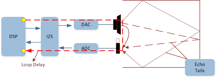
AEC Reference Function
AEC Reference function: Linear removal of echo signal mixing in microphone input without affecting the quality of
the desired speech signal. For tool configuration, when there is a need to configure the AEC Reference function,
select Primary Reference Out and Primary Reference In of Audio Category. The AEC Reference configuration
can be performed in the following three cases:
The figure shows the three cases of AEC Reference function.
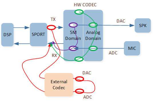
AEC Reference Function Cases
1. Case1: Reference signal from HW Codec DAC[5M]=>ADC[5M]=>SPORT RX=>DSP.
In this case, select Primary Reference Out and Primary Reference In and set them as Reference
Speaker and Reference MIC for tool configuration. There are three existing requirements as follows:
Note
The figure shows the tool configuration of the AEC Reference function between Audio and Record.
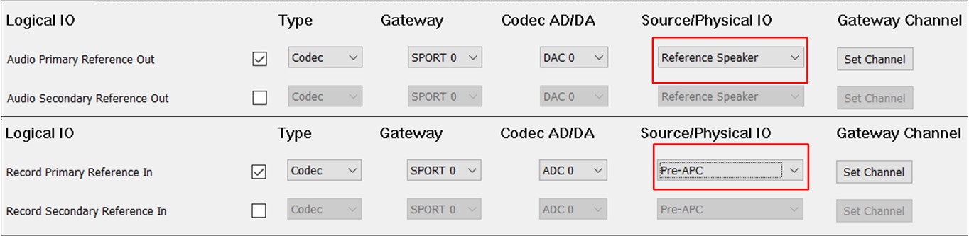
AEC Reference of Audio and Record
The figure shows the tool configuration of the AEC Reference function of Voice.
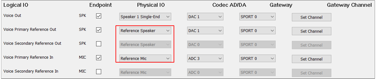
AEC Reference of Voice
The figure shows the tool configuration of the AEC Reference function of APT.
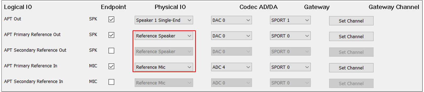
AEC Reference of APT
2. Case2: Reference signal from HW Codec DAC[5M]=>DAC[Analog]=>ADC[5M]=>SPORT RX=>DSP.
In this case, for tool configuration, select Primary Reference Out and set them to physical speaker
and select Primary Reference In and set them to physical microphone.
Note
The figure shows the tool configuration of the AEC Reference function for the second case.
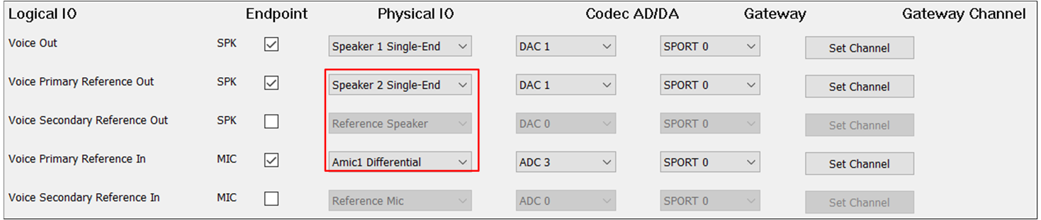
AEC Reference of Analog
3. Case3: Reference signal from External Codec DAC=> ADC=>SPORT RX=>DSP.
In this case, for tool configuration, select Primary Reference Out and configure Primary Reference In
as External Speaker and External MIC.
Note
The figure shows the tool configuration of the AEC Reference function for the third case.
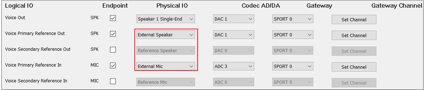
AEC Reference of External
Note
On RTL87x3E and RTL87x3EP,
DAC0can loopback toADC0\2\4,DAC1can loopback toADC1\3\5.On RTL87x3D,
DAC0can loopback toADC0\2\4,DAC1can loopback toADC1\3\5.