DSPConfig Tool
This documentation provides detailed guidance on the GUI to fine-tune the behavior related to the DSP FW part in the RTL87xx IC series. This DSPConfig Tool allows developers to configure parameters of built-in signal processing algorithms for voice and audio applications.
In addition, this DSPConfig Tool also provides user-friendly parameter fine-tuning functions, which can greatly shorten the turnaround time of parameter tuning, and they are:
Over-the-air Parameter Configuration
Run-time DSP configurations of embedded voice and audio enhancement functions via the wireless Bluetooth link.
Finally, this tool also supports the generation of DSP configuration files for RTL87xx toolchain, including flash download and mass-production software tools.
The terminology which will be used in the rest of this document is listed in: Terminology.
Abbreviations |
Descriptions |
|---|---|
Line-in |
An analog/digital input signal looped into DSP and then playback via analog/digital output interface as illustrated in Line-in Loopback Application. |
Far-end |
Denote the remote side phone caller in Bluetooth HFP mode as illustrated in Far-end and Near-end Sides. |
Near-end |
Denote the user of the Bluetooth audio device as illustrated in Far-end and Near-end Sides. |
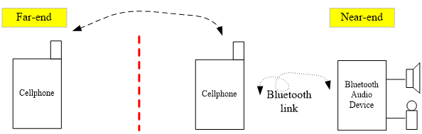
Far-end and Near-end Sides
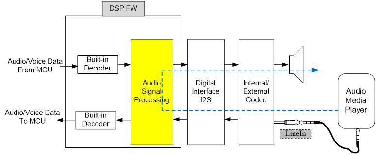
Line-in Loopback Application
Getting Started
Development Flow
Before starting the development, one must make sure of the types of IC package and ID number. Subsequently, RTL87xx IC Development Flow shows the development flow for Bluetooth audio products based on RTL87xx. The DSPConfig Tool generates a configuration binary file for the later MP Tool (See MP Tool user guide), which then merges binary files of the GUI Tool (Also see GUI Tool user guide) generated files, DSP system binary files, MCU binary files, etc.
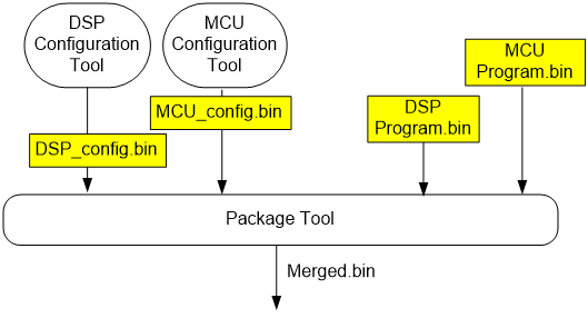
RTL87xx IC Development Flow
Select IC series and IC type which are going to be used, and then click Confirm button to enter MPPG Tool dialog. Please make sure the correct IC series and IC type are selected, or there may be an error in the pack procedure.
Bluetooth Connectivity and Hardware/Software Installation
Since the function for over-the-air parameter update via Bluetooth link is available in the tool, the developer must make sure that dongle RTL8761AUV or RTL8761AU is on hand and its Bluetooth driver is correctly installed in the windows OS.
To disable the built-in Bluetooth adapter, one can find the Bluetooth device via in the windows 7 OS. After disabling the Bluetooth adapter hardware, the removal of the Bluetooth driver program is also necessary.
In the case of successful installation of Bluetooth drivers, the Device Manager shows the Realtek Bluetooth 4.0 Adapter and no driver of other Bluetooth IC vendors shall still exist because it could possibly affect the operational behavior of the 'Realtek Bluetooth Adapter'.
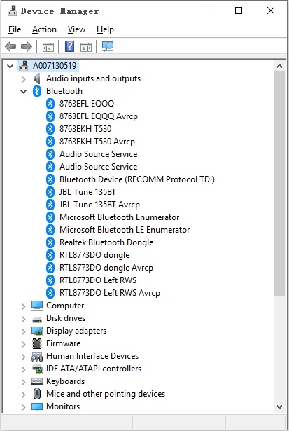
Successful Driver and Realtek Bluetooth Adapter
Overview of DSPConfig Tool
GUI of DSPConfig Tool
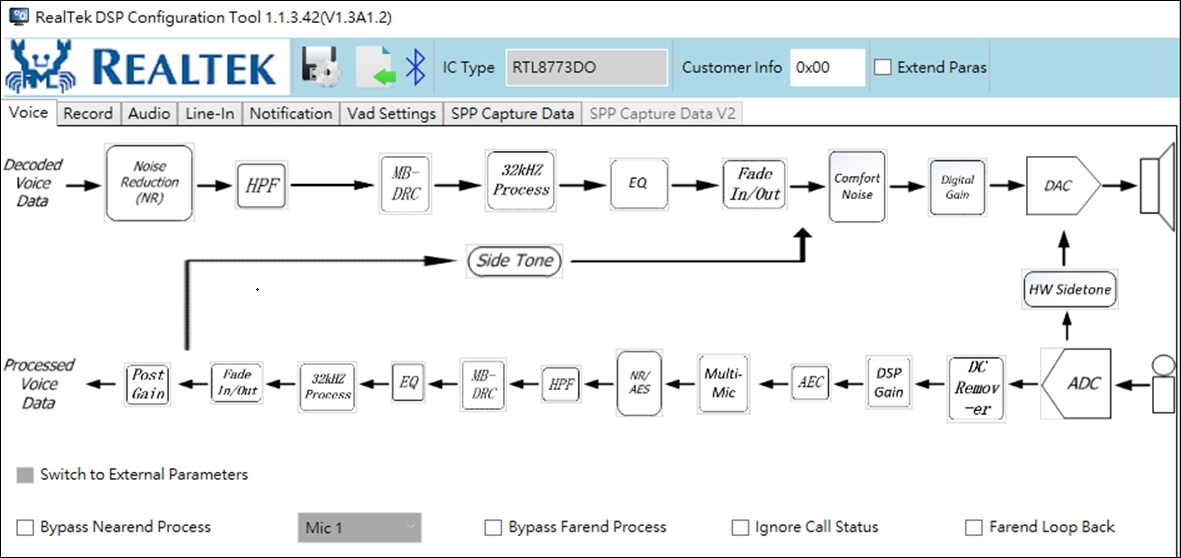
GUI of DSPConfig Tool shows the interface of DSPConfig Tool which allows developers to easily configure the DSP algorithmic functions, analog ADC/DAC analog properties and run-time configuration over the Bluetooth link.
Note
The layout of main/sub graphic user interface may be changed without notice.
Available Sub-pages
Commonly used algorithmic parameters of Bluetooth speaker/speakerphone and headset applications are classified as the following sub-pages:
For voice, audio and Line-in sub-pages, parameters and processing flow of proprietary signal-processing algorithms and configurations are displayed and users can easily fine-tune to targeted performance.
Button Functions
Button functions illustrated in GUI of DSPConfig Tool are summarized in Function Details of Buttons.
Button Name |
Note |
|
|---|---|---|
Save Config |
To save DSP configuration in binary format compatible for the input of MP Tool. |
|
Import Config |
To import saved DSP configuration. The import function also checks the version of imported DSP configuration compatible to the current DSPConfig Tool or not. |
|
SPP Control |
Choose Device |
Choose paired device in list. |
Connect |
To build up Bluetooth SPP link with selected DUT. |
|
Send CMD to DSP |
Send out DSP configuration based on current GUI settings to the DSP via Bluetooth SPP link MCU to DSP FW. Be correctly aware that this function needs to be authorized with password during connection process. This function is effective only when the DUT is in active voice (HFP) or audio (A2DP/Line-in) modes. |
|
EnableMultiLink |
Enable another Bluetooth device connection when doing online tuning with DSPConfig Tool. |
|
To send parameters in Audio tab via SPP, one must make sure that the DSP is playing sounds via A2DP or Line-in. Similarly, one can only send parameters of Voice tab while the DSP is playing and recording with an HFP link. The parameters sent by Send CMD to DSP are not stored in flash and thus are only effective until the A2DP/Line-in playback or the HFP is terminated.
The text editor Customer info for users to save some information, for example, user parameter version number.
Algorithmic Parameters and EQ Coefficient
Note
The Bluetooth DUT device shall be active and connected to the Realtek Bluetooth adapter, as shown in Bluetooth Setting, either in HFP, A2DP or Line-in mode as such the Send CMD to DSP operation is effective and can transfer the desired algorithmic parameters and EQ coefficients to the DUT.
Note
Whether 'Effect0~2' is checked or not in 'Mode#0~3', when Send CMD to DSP in audio or A2DP scenario, the parametric EQ parameters (currently selected EQ index in the parametric EQ interface) will be sent to the DUT. While if DSP configuration binary download to RTL8763Bx, the 'Mode' and 'Effect' must be valid or selected.
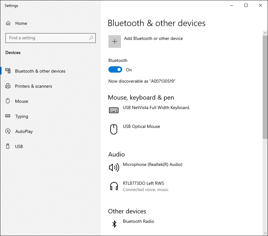
Bluetooth Setting
Voice Processing
This subsection introduces signal processing flow and block diagrams of voice algorithms as shown in GUI of DSPConfig Tool, consisting of NR, AEC, AES¹, HPF, Transducer EQ, and MB-AGC functions. Functions in Voice Processing summarizes the brief descriptions of each voice function. In addition, ADC/DAC gain settings are also configurable in this sub-page.
Abbreviations |
Descriptions |
|---|---|
AEC |
To linearly remove echo signal mixing in the microphone input without affecting the quality of the desired speech signal. |
NR |
To intelligently suppress stationary noise mixed within desired voice signal. Note that one-MIC solution can handle stationary noise suppression while two-MIC solutions can suppress stationary and dynamic noise sources. |
AES |
To apply the non-linear echo suppression to the AEC-processed signal. This could degrade the quality of the desired speech signal but can efficiently remove echo from the microphone captured signal where the processed voice quality can be optimized by fine-tuning AES parameters. |
Multi-MIC |
To suppress noise coming from unwanted directions while preserving the desired voice signal. This function requires two/three physical microphones on the Bluetooth audio device with proper placements and distance to achieve optimal performance. |
HPF |
To filter out low-frequency signal typically caused by PCB power noise. |
MB-AGC |
To dynamically control the signal level within desired power ranges in adjustable 1 to 3 frequency bands. |
Transducer EQ |
This equalizer is used to compensate the imperfect frequency response of microphone and speaker devices. |
DAC Gain |
To configure DAC gain settings including gain mapping for each level, default gain level for HFP mode and number of gain levels. |
ADC Gain |
Configure ADC gain to amplify the level of microphone signal. This ADC gain applies the same settings to both 'L/R' channels. |
DSP Gain |
To configure DSP gain for Primary/Secondary/FB MIC. |
Sidetone |
Choose suitable sidetone level to make the user hear own voice slightly. |
HW Sidetone |
HW sidetone has lower latency, however, less DSP processing. |
Comfort Noise |
Choose suitable comfort noise level to make the phone call more natural. |
AEC
Selectable AEC parameters are given in AEC Parameters and described in Parameters of AEC.
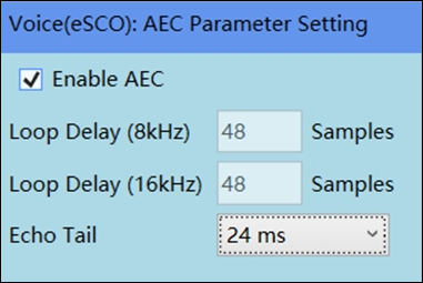
AEC Parameters
Note |
|
|---|---|
|
Loop Delay 8K/ Loop Delay 16K |
Denote the loop delay (unit in audio samples per channel) of echo signal passing through DSP output, speaker, the shortest echo propagation path in the air picked up by microphone and finally transfer back to the input of DSP as illustrated in If adopting either external ADC or DAC, the loop delay can only be selectable. In this case, the measurement of loop delay can be achieved by using the raw ADC/DAC data capture function, introduced in subsection, to measure the delay. |
Echo Tail |
Denote the longest echo propagation path as illustrated in Loop Delay and Echo Channel. A rule of thumb to configure the parameter of echo tail is that this parameter empirically needs no more than 24msec and 48msec for headset/headphone and speakerphone applications, respectively. Note that if echo tail is set beyond the required echo channel delay, echo performance will not be further enhanced due to more induced estimation error of residual echo signal. |
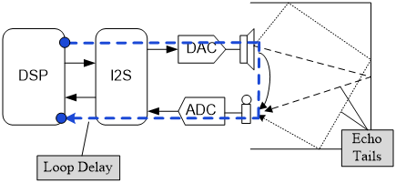
Loop Delay and Echo Channel
NR/AES
In this subsection, the parameter interface of non-linear voice enhancement functions, NR and AES, are introduced, and Far-end NR Settings and NR/AES/Dual MIC Settings at the Near-end show the tuning interface of Far-end NR and Near-end NR/AES functions, respectively.
Note
In the downstreaming (Far-end) signal in SCO (or Bluetooth HFP mode) mode, only a mono channel is available according to the Bluetooth specifications and, hence, only a one-MIC NR function is necessary at the downstreaming (Far-end) path.
Realtek NR technology includes one-MIC and two-MIC NR functions to process pseudo-stationary and dynamic noise sources, respectively. The definition of pseudo-stationary noise is the signal pattern whose signal power remains relatively stable over a long period of time within a fixed frequency range. Examples of such pseudo-stationary noise are like sounds of car engines, air-conditioners, and white/pink noises, etc. On the other hand, dynamic noise refers to the signal source not holding the pseudo-stationary property and its incident angle is beyond the desired range with respect to the desired speech signal. Configurable parameters of pseudo-stationary NR function are summarized in Descriptions of NR and AES Parameters.
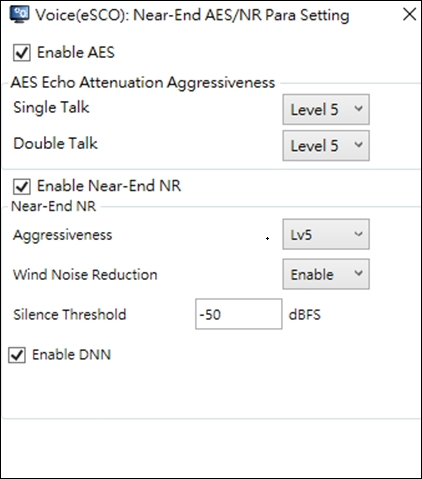
Far-end NR Settings
NR/AES/Dual MIC Settings at the Near-end
Function |
Parameters |
Note |
|---|---|---|
NR |
Single-Tone Pass-Through |
To enable tonal signal detection. If enabled, tone detection function can detect one and up to five tones, and prevent them from being suppressed by one-MIC NR function. The tone detection function is especially useful in measuring SNR and THD, because the test instrument often uses single-tone, usually at 1KHz, sinusoidal wave as the reference signal. |
|
Max Noise Attenuation |
Define the maximal suppression capability of NR function. Note that heavier NR suppression can remove more stationary noise from captured microphone signal in the tradeoff of more voice quality degradation. |
|
Aggressiveness |
Denote the aggressiveness level to suppress noise. 'Level 1' is the least aggressive level to suppress noise where 'Level 10' is the most aggressiveness NR level. Note that less NR processing can preserve desired speech quality but more likely to have more unprocessed ambient noise. |
|
|
Wind Noise Reduction |
Enable Wind Noise Reduction for Outdoor Headset |
|
|
Enhance Noise Naturalness |
Make Idle Noise More Natural |
|
AES |
Echo Attenuation Aggressiveness /Single Talk |
Denote the aggressiveness level to enable AES for echo suppression. 'Level 0' is the least aggressive level to kick-in AES where 'Level 14' is the most aggressiveness AES level. Note that less AES processing can preserve desired speech quality but more likely to have more unprocessed residual echo. |
|
Echo Attenuation Aggressiveness /Double Talk |
Denote the aggressiveness level to enable AES for echo suppression. 'Level 0' is the least aggressive level to kick-in AES where 'Level 14' is the most aggressiveness AES level. Note that less AES processing can preserve desired speech quality but more likely to have more unprocessed residual echo. |
|
|
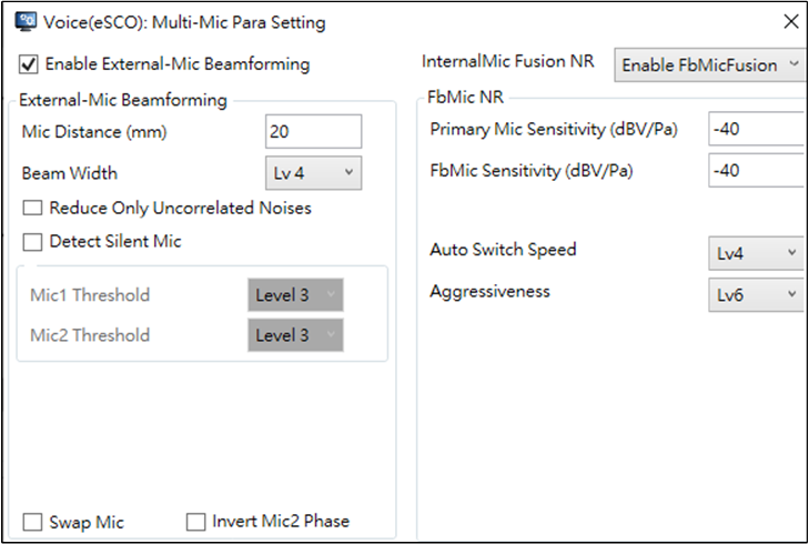
Multi- MIC NR |
MIC Distance |
The distance between two microphones. The unit is mm (millimeter). The microphone distance must be in the range of 10mm to 70mm. |
Voice Direction |
Denote the desired AoA direction of desired speech. Dual-MIC NR Voice Direction illustrates the definition of AoA, θ, with respect to the placement of the microphone array. Selectable AoAs in the DSPConfig Tool are given as +/-0, +/-15, +/-30, and +/-45 degree. Note that, due to the symmetric nature of two-microphone arrays, incident angles, θ and –θ, are indistinguishable. 'MIC 0' is the microphone closer to the mouth. |
|
Post-Processing |
Enabling post-processing of dual-MIC NR can suppress more noises at the cost of degrading voice quality. |
|
|
Max Noise Attenuation |
The maximal noise suppression by post-processing. |
|
Aggressiveness |
To set the aggressiveness of the post-processing of dual-MIC NR. Higher aggressiveness level can suppress more noises at the cost of degrading voice quality. |
|
|
Primary MIC Sen -sitivity/FB MIC Sensitivity |
To Set MIC Sensitivity Including Primary MIC and FB MIC |
|
|
Auto Switch Speed |
When FB MIC Detected Speech Signal, NR Will Change Dual-MIC to Multi-MIC |
|
Send CMD to DSP |
To test if each microphone functions normally and if placement of the primary and reference microphone is correct. The placement of microphones is depicted in Requirement of Microphone Placement. In test mode, dual-MIC NR does nothing but output the signal of the user-selected microphone. One can test if the primary microphone functions normally by selecting 'MIC 1'. Similarly, to test the reference microphone, select 'MIC 2'. |
|
Swap MIC |
With this option checked, the dual-MIC NR algorithm takes the microphone connected to as the main microphone and the microphone connected to
this option only when the PCB layout is wrong. |
|
|
Invert MIC 2 Phase |
With this option checked, the 'MIC 2' signal is multiplied by -1 before processed by dual-MIC NR. Check this option only when the microphone polarity is wrongly connected. |
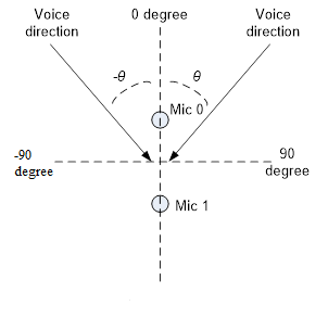
Dual-MIC NR Voice Direction
Realtek's dual MIC algorithm can track the movement of the headsets. However, the most desirable angle should be assigned by configuring the parameter 'Voice Direction' as listed in Descriptions of NR and AES Parameters.
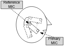
Requirement of Microphone Placement
Dual-MIC Industrial Design Guide
Microphone Placement
The primary MIC (connected to MIC1_P, MIC1_N pin) must be placed closer to the mouth while the reference MIC (connected to MIC2_P, MIC2_N pin) must be placed closer to the ears as depicted in Requirement of Microphone Placement, and that the distance between microphones must be in the range of 15 mm to 30 mm. The opening of the primary microphone should be directed to the mouth and the opening of the reference microphone should be directed away from the face. The structural design of the headset should avoid blocking the direct path from the mouth and the environment to each microphone. The reference microphone is better directed to the left or right of the one who wears the headset, not to the back, in order to receive sounds coming from the mouth directly. See Recommended Microphone Placement for desirable microphone placement and see Undesirable Microphone Placement for the placement that should be avoided.
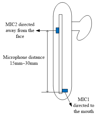
Recommended Microphone Placement
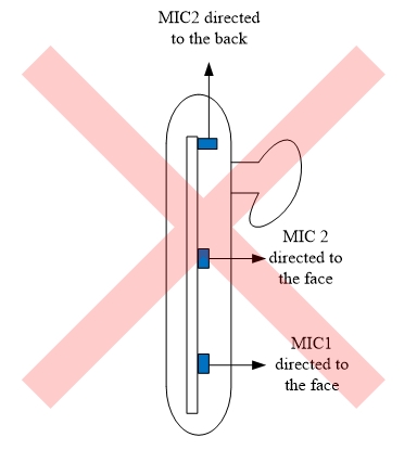
Undesirable Microphone Placement
Parameter |
Test Condition |
Requirement |
|---|---|---|
Directivity |
Omni-directional |
|
Sensitivity |
1 kHz, 94 dB SPL |
>-45 dBV/Pa |
SNR |
>60 dB |
|
THD |
94 dB SPL |
<1% |
114 dB SPL |
<5% |
Other Design Suggestion
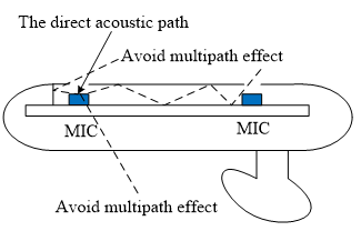
The microphone pairs must be of the same part number. MEMS microphones are suggested since they have smaller production variance than ECM. The microphones should be isolated and sealed. Sealing and isolating microphones is to ensure that each microphone only picks up sounds from its own opening on the cover and to avoid multipath effect. Avoid Multipath Effect shows an example of the acoustic paths that should be avoided. Placing microphones closer to the opening on the cover can help to reduce multipath effect. See Place Microphones Closer to the Opening on the Cover. To test if both microphones are isolated properly, one can use the test mode of the dual-MIC NR tuning interface to enable only one of the microphones and compare the sound level when the microphone's opening on the cover is sealed (with fingers) and when it's not. When the opening is sealed, the sound level picked up by the microphone should be 20 dB (or more) less than the sound level when the opening is not sealed. The speaker should be placed closer to the reference microphone than the primary microphone.
Avoid Multipath Effect
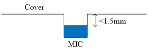
Place Microphones Closer to the Opening on the Cover
High-Pass Filter (HPF)
HPF is mainly to remove unwanted low-frequency signal/noise such as power noise generated by the power adapter, and wind noise, etc. Selectable cutoff frequencies range from 90 Hz to 300 Hz.
Note
Higher cutoff frequency may also filter out the fundamental pitch frequency of the desired voice signal.
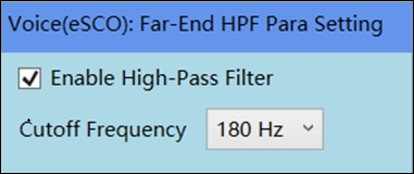
Parameter of HPF
Transducer EQ
The transducer EQ supports up to 10-stage IIR filter for both speaker/microphone paths and 16 KHz sampling rate.
As shown in Interface of Customizable 5-Stage EQ, the tuning interface of customized EQ is based on the parametric equalizer where the parameter set of each EQ stage includes 'Frequency', 'Gain' and 'Q' as summarized in Parameters of Customizable EQ.
Note
The number of desired EQ stages, 'Stage' in Interface of Customizable 5-Stage EQ, must be selected to physically enable the EQ function. In addition, the frequency response of each EQ stage can be displayed in logarithmic scale.
Note |
|
|---|---|
Frequency (Hz) |
The desired center frequency of each EQ stage. The unit is Hz. |
Gain |
The boost/attenuation gain in dB scale at the selected frequency. |
Q |
The bandwidth of the gain applied at the selected center frequency. If the value of Q is closer to zero, the wider bandwidth it is, and vice versa. |
EQ Type |
There are 5 EQ types supported. Peaking/Highpass/Lowpass/High Shelving/Low Shelving. |
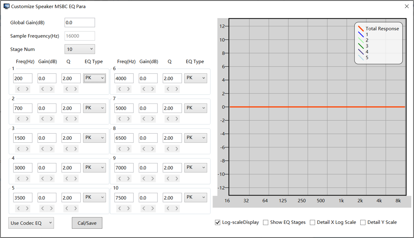
Interface of Customizable 5-Stage EQ
Multi-Band Automatic Gain Control (MB-AGC)
In Block Diagram of MB-AGC Function, MB-AGC function comprises 'Signal Separator' and three AGCs for three frequency bands. 'Signal Separator' function is to separate the input signal into three frequency bands whose frequency boundaries are selectable, ranging from 500 Hz to 7.5 kHz and 500 kHz to 7.5 kHz of first/second and second/third frequency bands, respectively.
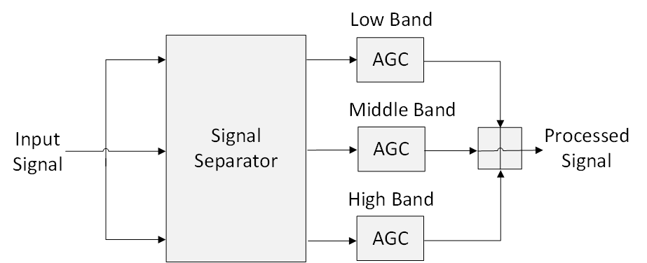
Block Diagram of MB-AGC Function
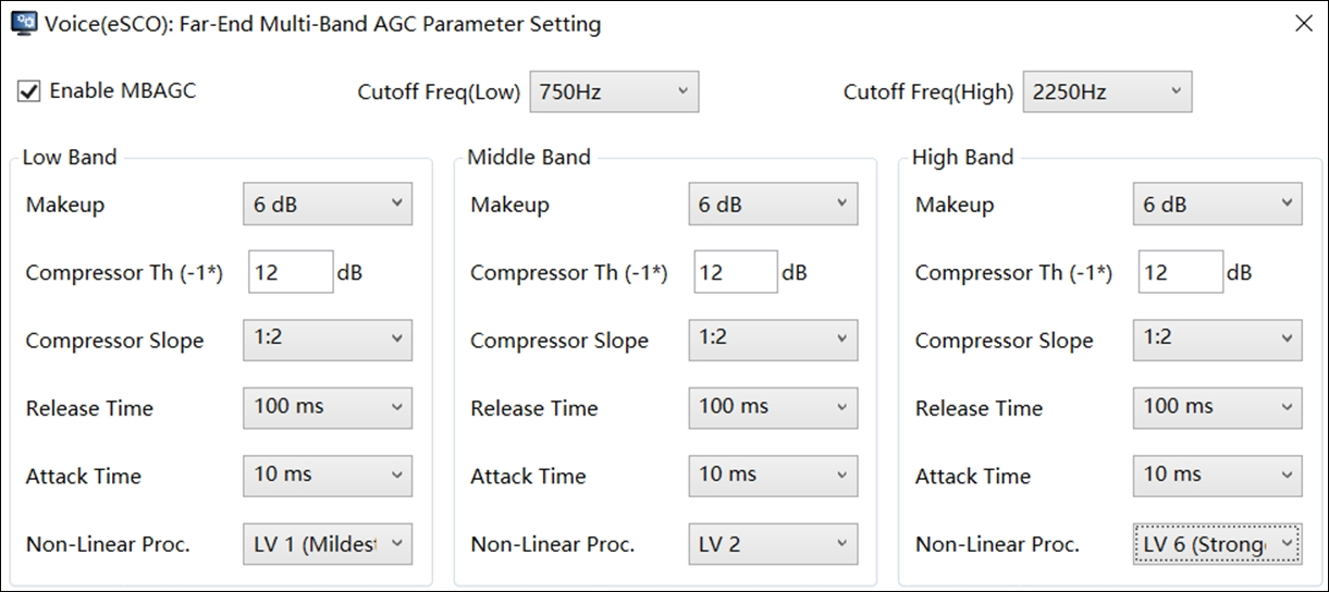
Parameter Interface for MB-AGC
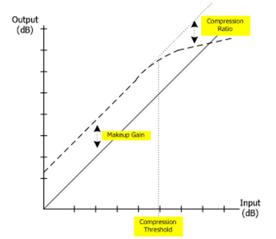
AGC function is used to adjust the input signal to its desired power range by attenuating the level of strong peaks and amplifying weaker peaks. With separated frequency bands, AGC can enhance desired speech signal loudness more efficiently, especially for those bands easily being inaudible due to the hearing masking effect. Parameter Interface for MB-AGC shows the interface for the parameter of MB-AGC, and functions of these parameters are summarized in Parameters of MB-AGC Function. Among them, the definition of the time constant for 'Attack Time' and 'Release Time' is a period of time for a system to reach 1-1⁄e=63% of its final value. The 'Attack Time' is the period of time to suppress the signal when the input level hits the defined loud volume threshold. During the 'Release Time', the MB-AGC function boosts the soft input signal up to the defined 'Makeup Gain'. Parameters of MB-AGC Function shows the illustration of MB-AGC parameters including 'Makeup Gain', 'Compression Ratio', and 'Compression Threshold'.
Each frequency band has its own independent set of AGC parameters. One can select the number of frequency bands from 1 to 3 frequency bands. However, more selected frequency bands consume more DSP computing power and hence the current consumption as well. The MB-AGC can also compensate for distorted voice quality by noise reduction and echo cancellation algorithms by balancing signal power in each frequency band.
Note |
|
|---|---|
Attack Time |
The time constant to suppress input signal to desired level as shown |
Release Time |
The time constant to release from the suppression back to its desired level. |
Makeup Gain |
The maximal boost gain that AGC function can apply to the input signal. |
|
Compression Threshold |
Amplitude threshold to define the boundary between loud and soft signal levels. |
|
Compression Ratio |
The ratio to suppress loud audio signals exceeding their average signal level exceeding the 'Compression Threshold'. Ex: If the ratio is R, compression threshold is TH dBOv, and input signal level is x dBov. The output signal level is: Output signal level = TH + (x - (TH)) / R. |
|
Cutoff Frequency (Low) |
The cutoff frequency to distinguish middle and low bands. |
|
Cutoff Frequency (High) |
The cutoff frequency to distinguish middle and high bands. |
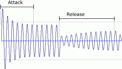
Attach and Release Time of AGC Parameters
DRC Parameters
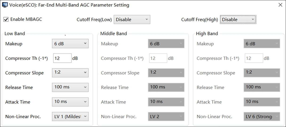
The MB-AGC allows developers to select the number of bands with defined cutoff frequencies as illustrated in One-band Setting with Cutoff Frequency at 1000 Hz/Two-band Setting with Cutoff Frequency at 1000 Hz/Two-band Setting with Cutoff Frequency at 2500Hz/Three-band Setting with Cutoff Frequencies at 1000Hz and 2500Hz. One can select one/two/three-bands with various cutoff frequencies.
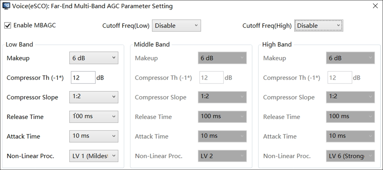
One-band Setting with Cutoff Frequency at 1000 Hz
Two-band Setting with Cutoff Frequency at 1000 Hz
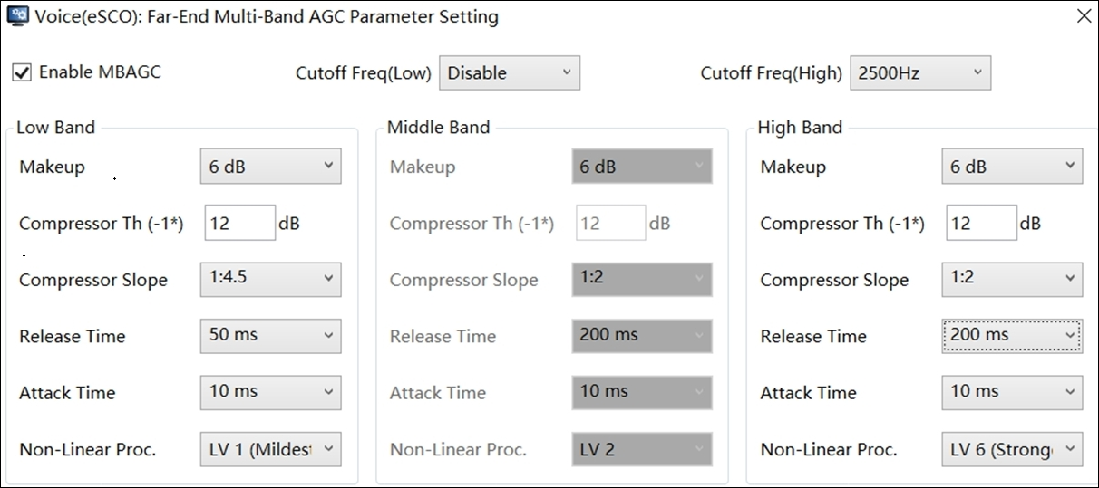
Two-band Setting with Cutoff Frequency at 2500Hz
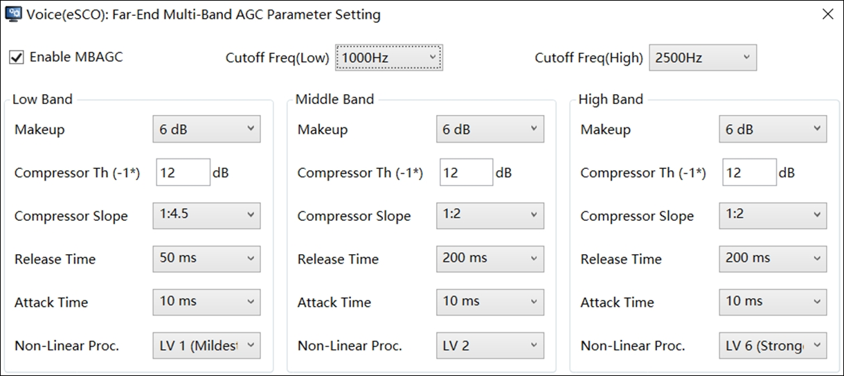
Three-band Setting with Cutoff Frequencies at 1000Hz and 2500Hz
Audio/Line-in Processing
This chapter discusses configurations of audio processing algorithms designed for various Bluetooth audio applications.
Audio Sub-page
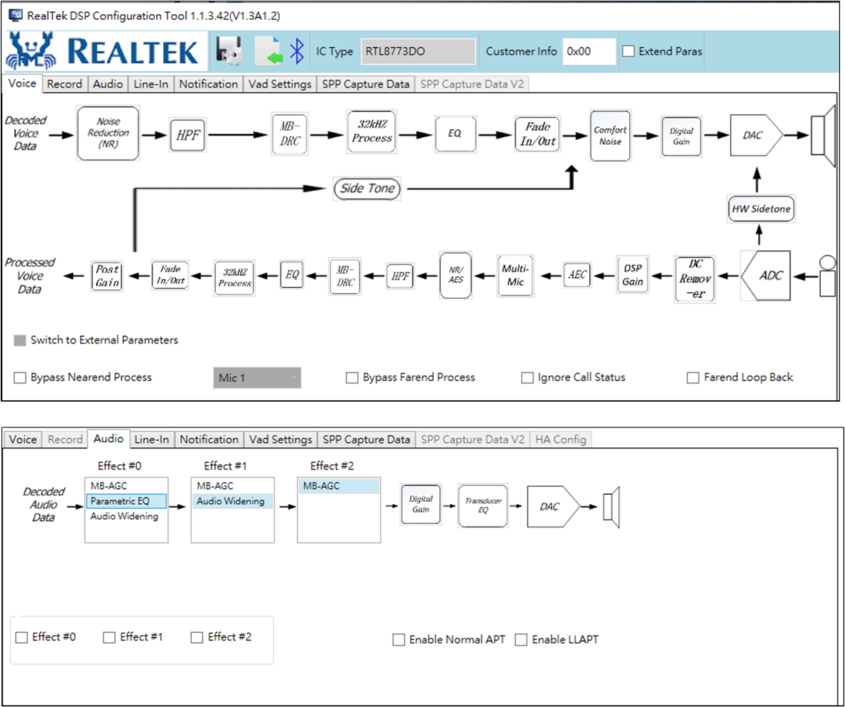
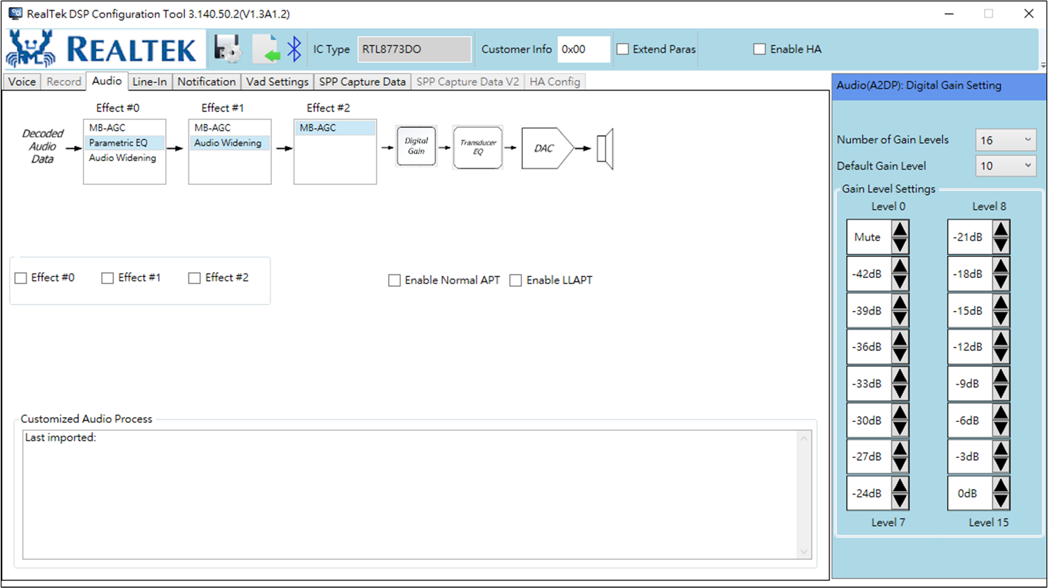
Audio Sub-page demonstrates configurations and block diagrams of Realtek's audio processing algorithms in Bluetooth A2DP/Line-in mode. In this subsection, supported audio algorithms include MB-AGC, parametric EQ, audio widening, and APT functions. Besides, interfaces to configure transducer EQ for speaker path, ADC and DAC gain are also shown. The detailed description of each block is summarized in Detailed Descriptions of Audio Processing Functions.
Note |
|
|---|---|
MB-AGC |
Dynamically control the output volume range of audio signal. |
Parametric EQ |
To boost/attenuate the specific frequencies to enhance audio signal quality. |
|
Audio Widening |
To create a widened audio field based on the original audio signal, especially effective for stereo speaker placing very close apart. |
Suppress Gain |
Suppress gain is a global negative gain for mode change with button. |
Normal APT |
To mix the processed microphone signal with down-streamed audio data. The purpose of APT is to allow headset users to be able to perceive the ambient sound while listening to Bluetooth audio streaming to reduce the risk of ignoring any alert signal in the ambient environment. |
LLAPT |
LLAPT has lower latency compared with Normal APT, it is noteworthy that LLAPT should be turned on in MCU settings in advanced, LLAPT EQ is designed in ANC Design Tool. |
In addition to the algorithmic function, the audio sub-page also allows developers to have three different combinations of audio processing algorithms, which will be introduced in the rest of this chapter.
In RTL8763 IC, the Line-in mode is to capture audio signal from external media player, which are then passed to DSP for further processing before converting back to analog signal played out by speaker devices. Based on the DSP architecture design of RTL8763 IC platform, the Line-in mode is designed to share the same parameter set of audio algorithms, including DAC Gains, MB-AGC, 'Parametric/Transducer EQs', Audio Widening and the configurations of sound effect in each selectable mode. However, the only difference is that ADC settings are not following Audio (A2DP) setting due to much less ADC amplification gain required in Line-in mode than the APT function of Audio (A2DP) mode.
Note
The APT mode is not supported in Line-in mode because APT mode needs to have the microphone enabled to capture ambient sound level.
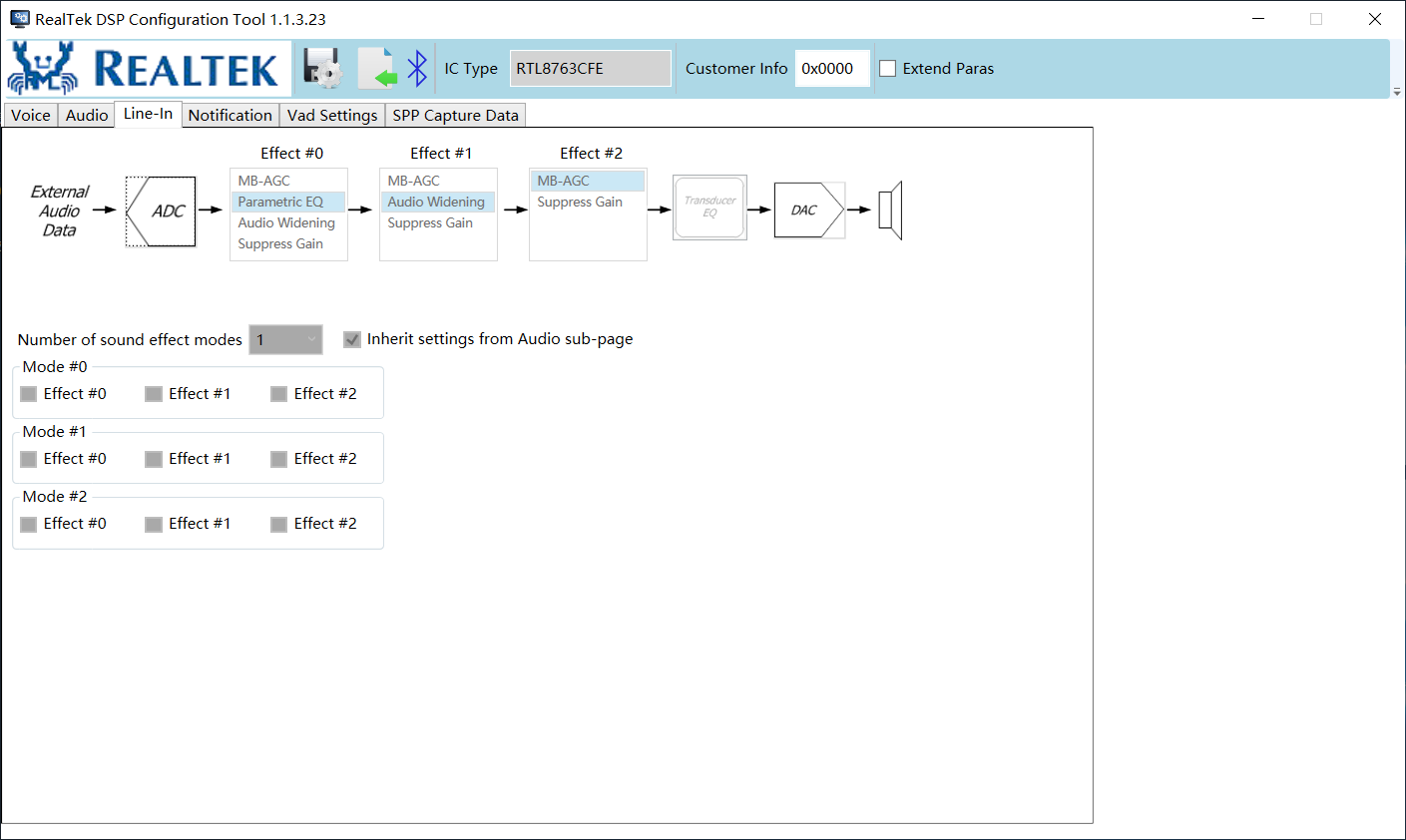
Line-in Sub-page
Mode/Effect Configurations
Audio processing algorithms can be arranged in terms of processing order in the effect configuration region as in Effect and Mode Configurations in Audio Process Sub-page. The configuration interface of each sound effect will be popped up when it is selected in the list box of each effect. Subsequently, developers also need to configure at most three modes containing different algorithm configurations which are able to be switched from one mode to another during the audio playback with external triggers from, i.e. physical button on evaluation board or cellphone APP.
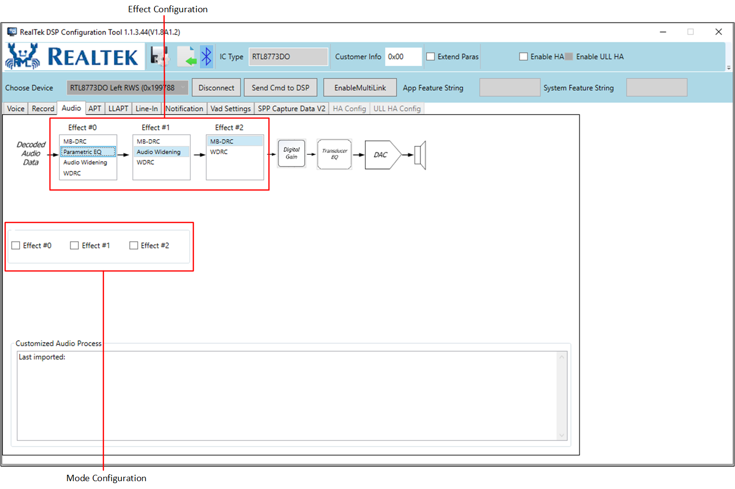
Effect and Mode Configurations in Audio Process Sub-page
MB-AGC
The parameter tuning interface is identical to the voice processing part and is enabled by default. The only difference is the selectable cutoff frequencies.
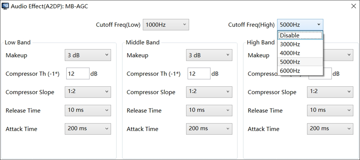
Interface of MB-AGC for Audio Function
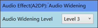
Parametric and Transducer EQs
Audio transducer EQ default sampling frequency is 44.1 KHz, and coefficients of 48 KHz sampling rate are automatically generated and EQ coefficients of both sampling rates will be saved in the parameter file while exporting DSP configuration. And the Parametric EQ interface is different from transducer, and parametric EQ stage number can be up to 10.
There are up to 10 user-defined EQ parameters for each IC package. User-defined EQ parameters can be changed via DSPConfig Tool.
When one EQ Index is selected in the Combobox, the corresponding EQ parameter and EQ frequency response is displayed in the DSPConfig Tool UI.
If any parameter (stage number/frequency/Q/Gain/EQ type/global gain) is changed, click the button Apply to make sure the EQ coefficients are correctly computed.
The EQ 'IsEnable' group is for MCU to define which EQ(s) is/are enabled or not. If enabled, end-user can select and activate the corresponding EQ.
Note |
|
|---|---|
Frequency(Hz) |
The desired center frequency of each EQ stage. The unit is Hz. |
Gain |
The boost/attenuation gain in dB scale at the selected frequency. |
Q |
The bandwidth of the gain applied at the selected center frequency. If the value of Q is closer to zero, the wider bandwidth it is, and vice versa. |
EQ Type |
There are 5 EQ types supported. Peaking/Highpass/Lowpass/High Shelving/Low Shelving. |
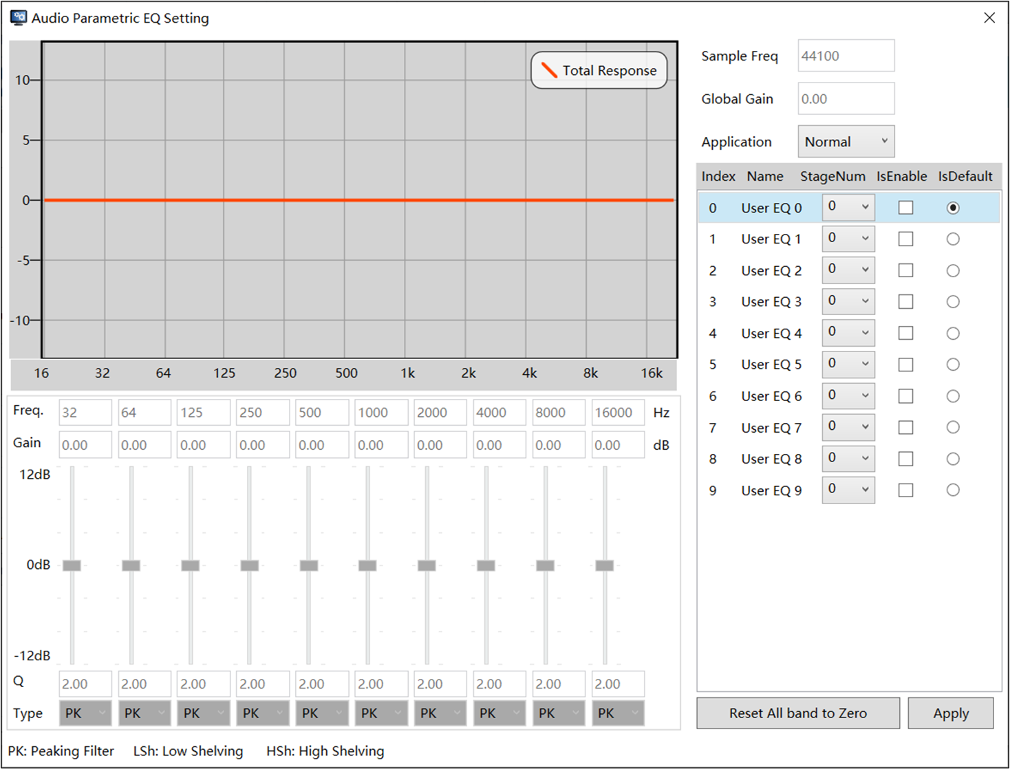
Parametric EQ Interface for Audio
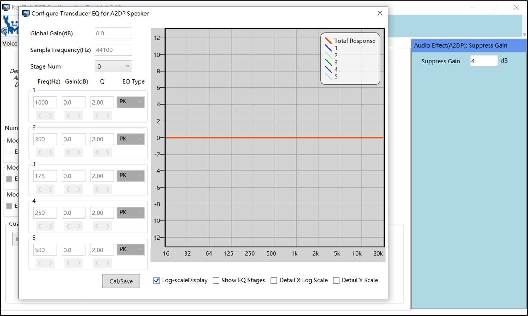
Audio Widening
The audio widening function is to expand the audio image, especially useful for the narrow audio field generated by stereo speakers placed closely apart.
Note
This function is only useful when the channel number of the audio decoder output is more than one channel.
A very simple tuning interface is provided as in Parameter of Audio Widening Function.
Parameter of Audio Widening Function
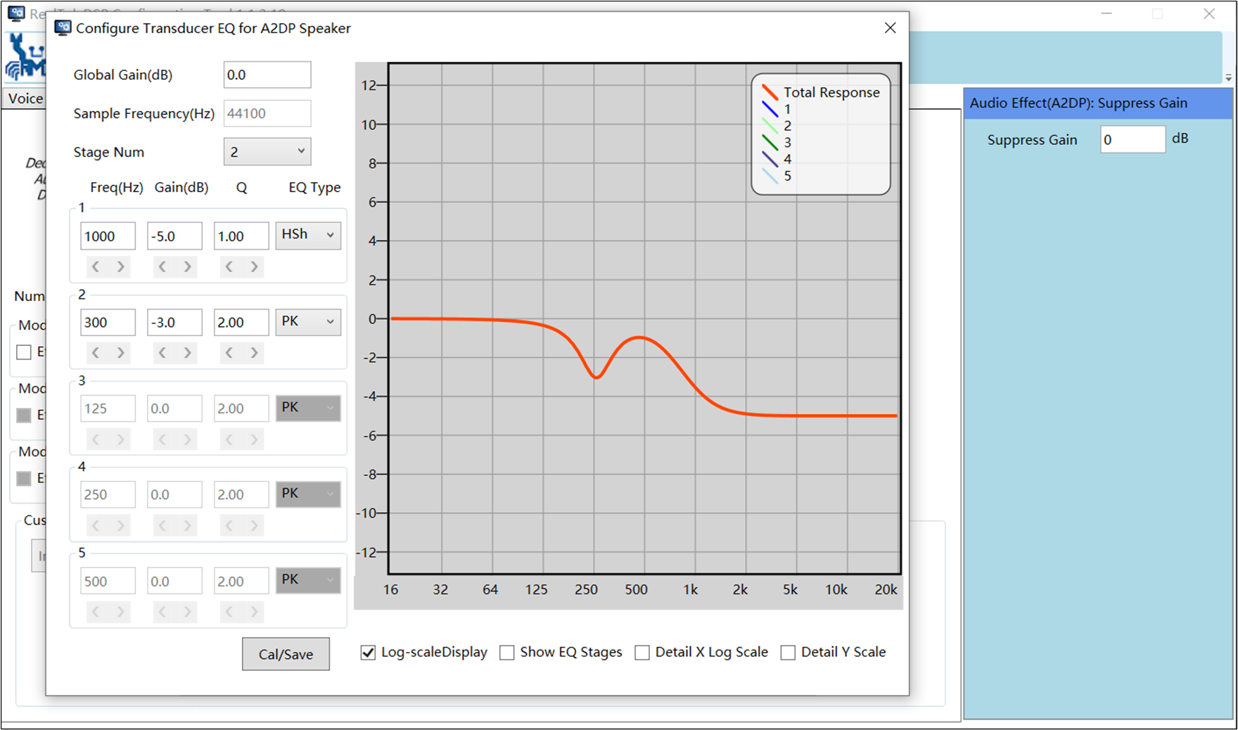
Suppress Gain
'Suppress Gain' is a global negative gain for mode change with button. For example, the user can set 2 audio modes, one has EQ setting with negative gain to avoid saturation (as One Example of Audio Mode Setting shows), the other one mode does not have any sound effect setting. In this case, the user may perceive the difference in volume. So we can set the suppress gain in second mode as Other Example of Audio Mode Setting shows to compensate the negative gain.
One Example of Audio Mode Setting
Other Example of Audio Mode Setting
Audio Pass-Through (APT)
The APT mainly consists of DC remover, noise reduction, de-howling, and mix gain control functions. The noise reduction function is to suppress the ambient noise. The de-howling function is to dynamically control the microphone input gain to avoid the howling effect. The performance of the de-howling function is based on the echo attenuation. The echo from the microphone-captured signal must be attenuated by at least 15 dB. The selectable parameters shown in Interface of AGC Parameter in APT are listed in Parameters of De-howling Function for the de-howling function.
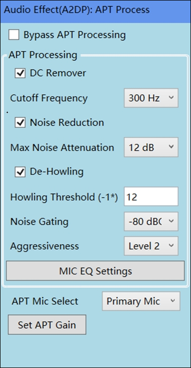
Interface of AGC Parameter in APT
Note |
|
|---|---|
Howling Threshold |
The detected digital level of ADC pick-up input signal. If A2DP playback is active and the digital input level exceeds the selected threshold, de-howling function starts to kick in to lower the ADC gain to avoid the howling from happening. |
Noise Gating |
If the detected digital input level is smaller than the selected threshold, the signal will be suppressed. |
Aggressiveness |
Denote the aggressiveness level to suppress howling. 'Level 1' is the least aggressive level to suppress howling where 'Level 4' is the most aggressiveness level. |
In Parameters of ADC Gain Setting, the analog gain is imported from RCFG file. The DSPConfig Tool can only view or use the analog gain. If you need to adjust it, you must set it using the MCUConfig Tool.
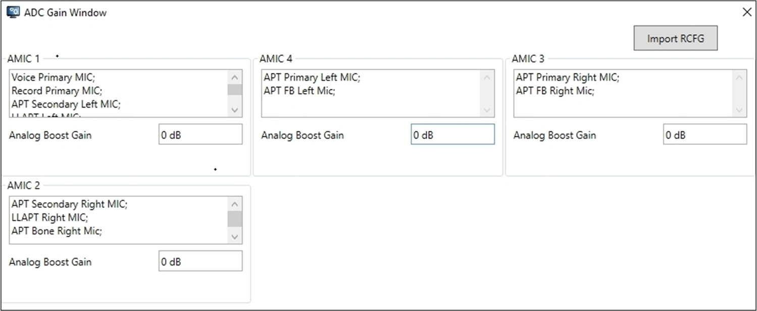
Parameters of ADC Gain Setting
Low Latency Audio Pass-Through (LLAPT)
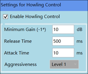
Parameters of LLAPT Howling Control Setting
Note |
|
|---|---|
Minimum Gain |
The detected digital level of ADC pick-up input signal. If A2DP playback is active and the digital input level exceeds the selected threshold, the de-howling function starts to kick in to lower the ADC gain to avoid the howling from happening. |
Release Time |
The time constant to release from the suppression back to its desired level. |
Attack Time |
The time constant to suppress input signal to desired level as shown |
Aggressiveness |
Denote the aggressiveness level to suppress howling. 'Level 1' is the least aggressive level to suppress howling where 'Level 4' is the most aggressiveness level. |
Note
It is worth mentioning LLAPT and normal APT need MCU setting in advance before enabling in DSPConfig Tool. LLAPT filter needs to be designed in ANC Design Tool (It must have at least one group of ANC when creating an APT group. This ANC Group needs to enable FF path).
For more details, please see LLAPT_tuning_guide_draft_20200430_v2.
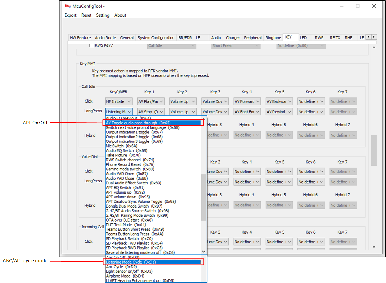
MCUConfig Tool Setting
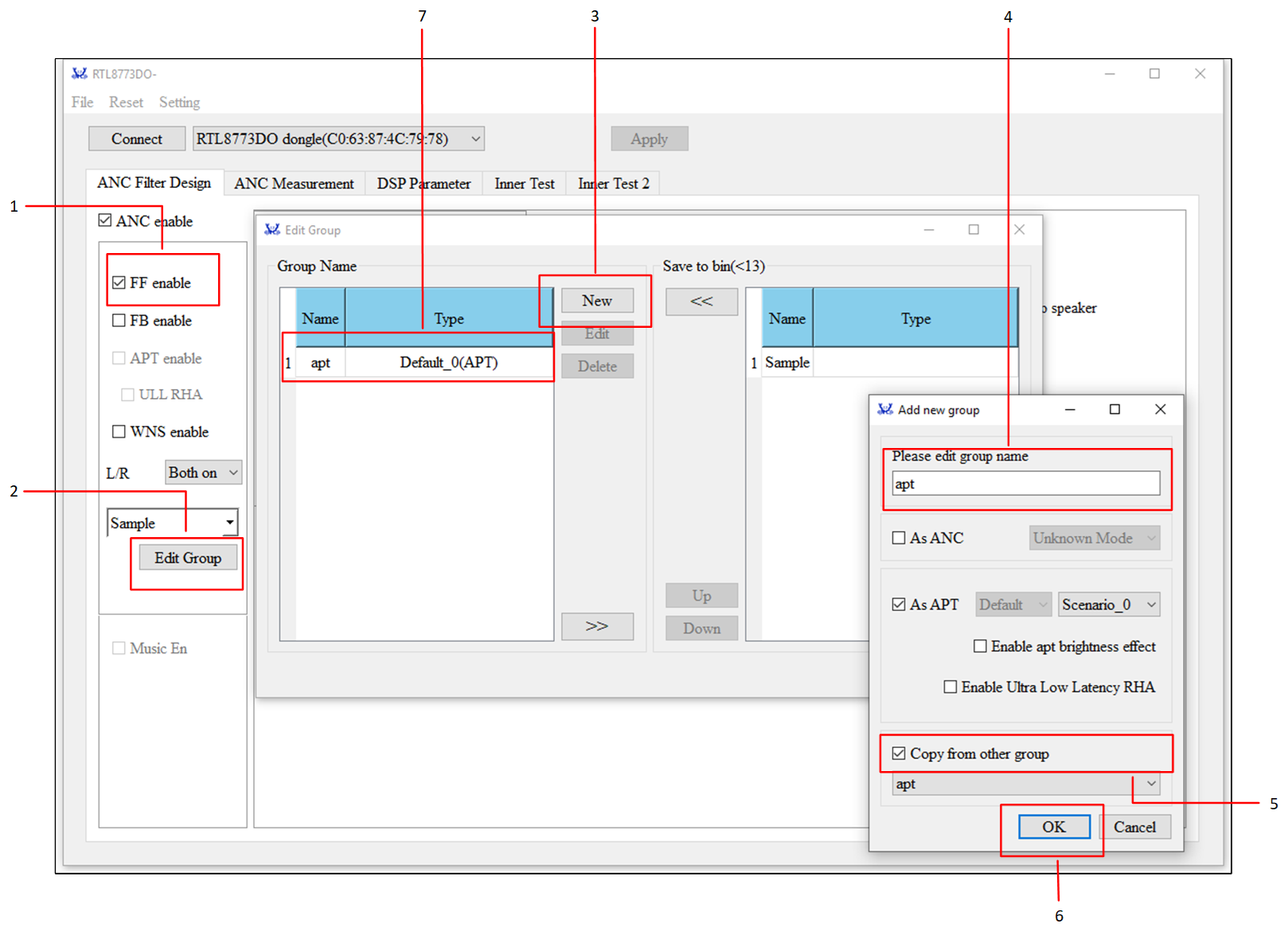
ANC Design Tool Setting
VAD Settings
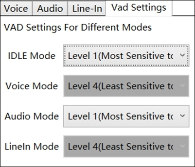
VAD Setting
VAD is working only in idle and A2DP mode. 'Level 1' means the module is most sensitive to detect a voice activity, 'Level 4' means the module is least sensitive to detect the voice activity. VAD is not supported in voice and Line-in mode.
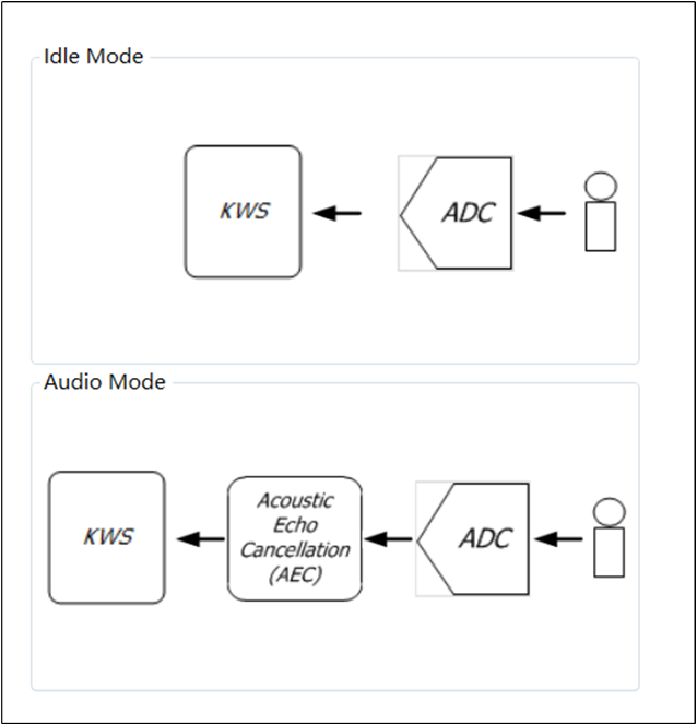
VAD Working Mode
ADC gain settings are shown in this VAD settings page, and the ADC gain changed in this VAD settings page will lead to the ADC gain in the voice page, and the ADC gain changed in the voice page will lead to the ADC gain in this VAD page.
Recommended Fine-tuning Method for Voice Processing
The methodology to fine-tune the performance of voice processing is brought up in this chapter. A good parameter set for NR/AEC functions must abide by the following requirements:
High Microphone/Speaker Volume
Echo-free at the Microphone Path
Double-talk (DT) Performance after Processed by AEC/AES Algorithms
Voice Clarity at Microphone/Speaker Paths
Ambient Noise Suppression without Degrading the Desired Voice Quality
Parameter Tuning Flow for Voice Processing provides recommended fine-tuning steps to optimize the performance of voice processing algorithms for speakerphone and headset applications.
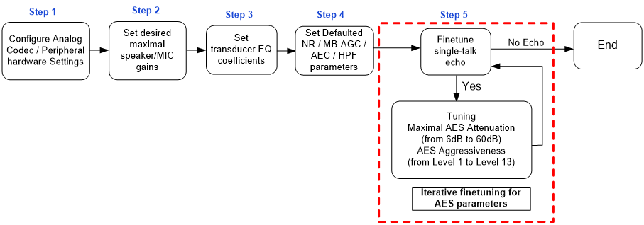
Parameter Tuning Flow for Voice Processing
The details of these steps are explained as follows.
The hardware configuration shall be correctly programmed before any parameter fine-tuning for voice algorithms, following the programming guidelines. For example, dual-microphone noise reduction is only supported when two physical microphone devices are connected to the hardware.
-
The speaker output of each gain level shall be determined following the principle that there should be a lower gain difference (<=2dB) between gain levels at high volume and a bigger gain difference (>2dB) between those at softer volume. In addition, the maximal gain level shall be determined by the criteria of acceptable THD performance since poor THD could severely degrade the AEC performance.
A rule of thumb for the THD criteria at the maximal speaker volume shall be less than 5%. Unlike multiple speaker gain levels, only one gain level is needed to be configured for ADC microphone gain. The principle to set a proper ADC gain also follows the less-than-5% THD criteria to have better AEC performance. On the other hand, the slope-overload nature of the CVSD codec may distort the output signal if the input signal volume is too high. As a result, it is not always good to set the MIC gain to its maximal level.
Note
The MIC signal recorded by the Realtek Bluetooth adapter is 6 dB less than the actual level.
-
In light of having optimal voice quality, the transducer EQ shall be properly configured to compensate for the imperfect response of selected speaker and microphone devices. Snapshots illustrated in Tolerance Mask for the Bluetooth Send Sensitivity Frequency Response and Tolerance Mask for the Bluetooth Receive Sensitivity Frequency Response (in Bluetooth standard HPF 1.6) show the frequency masks of processed microphone and speaker paths, respectively.
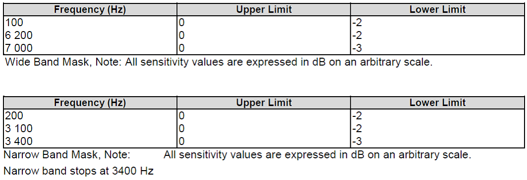
Tolerance Mask for the Bluetooth Send Sensitivity Frequency Response
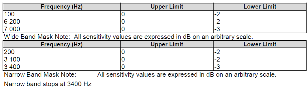
Tolerance Mask for the Bluetooth Receive Sensitivity Frequency Response
Apply default parameters for MB-AGC, NR, HPF, and AEC for both speaker and microphone processing paths and download the DSP configuration file to the IC.
This step is to fine-tune the AES performance step. It basically breaks into two parts, which are single-talk echo and double-talk echo tunings.
Tip
Single-talk echo: 'Maximal AES Attenuation' and 'Aggressiveness' introduced in section 0 are responsible for tuning the single-talk echo performance. As a rule of thumb, firstly adjust the parameter of 'Aggressiveness' from 'Level 1 (Least aggressive)' to 'Level 14 (Most aggressive)'. If the value of the 'Maximal AES Attenuation' is 30 dB and single-talk echo is not able to be effectively suppressed, subsequently one can continue to fine-tune the 'Maximal AES Suppression' from 30 dB toward the value 60 dB.
Note
Although the selectable value of 'AES Aggressiveness' can be up to 'Level 14', the voice quality of the processed microphone signal becomes more aggressive.
SPP Capture Data
The tool can be used to capture audio data for data analysis and other scenarios. This function provides raw data capture in the following three modes:
A2DP mode: Captures raw speaker data from the playback path.
Fake SCO mode: Captures raw microphone data to simulate a call.
HFP mode: Captures raw speaker and microphone data during a call.
SPP Capture Setting
UI setting: MCU UI needs to support SPP capture as below:
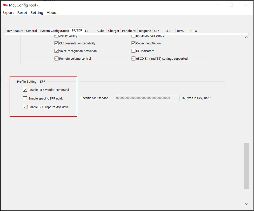
Support Capture in MCUConfig Tool
Capture Flow:
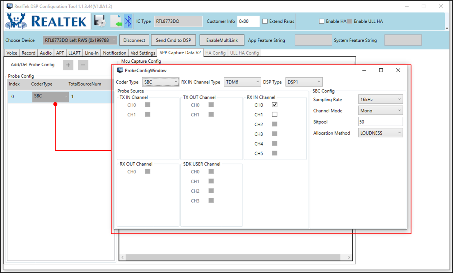
Set
ProbeConfigWindow.Press Enter Test Mode.
Press Enter SCO Mode.
Press Start to start capture data.
Press Stop to stop capture data.
Captured data will be saved in
Audio.binfile (Audio.binsaved in path with DspConfigTool.exe).
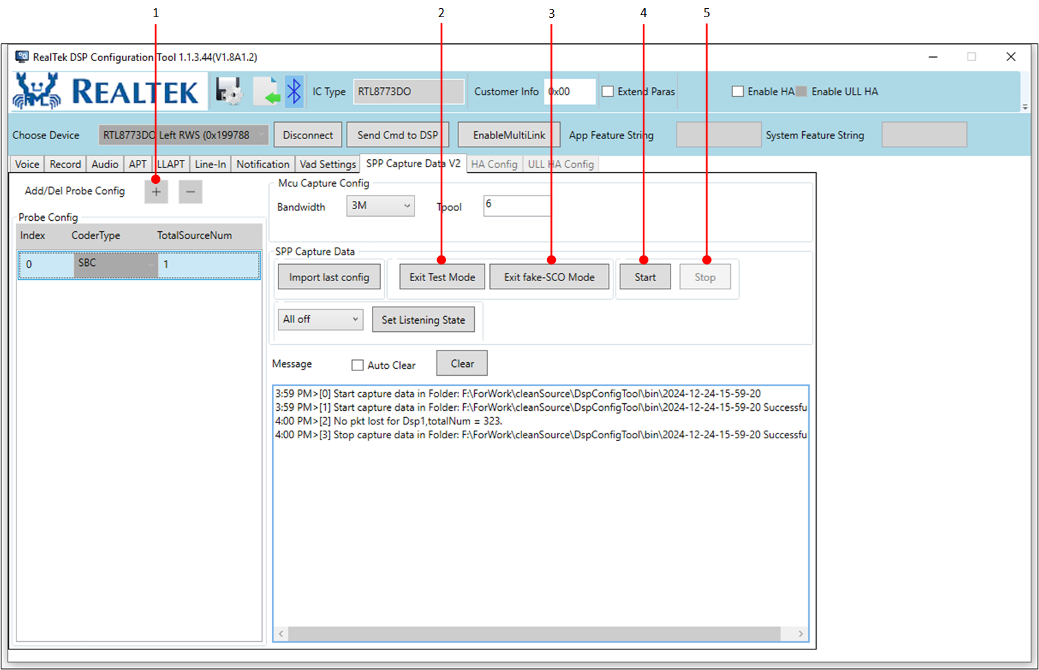
Start/Stop Capture in DSPConfig Tool
More details please see: DSPToolTraining_v1.21.