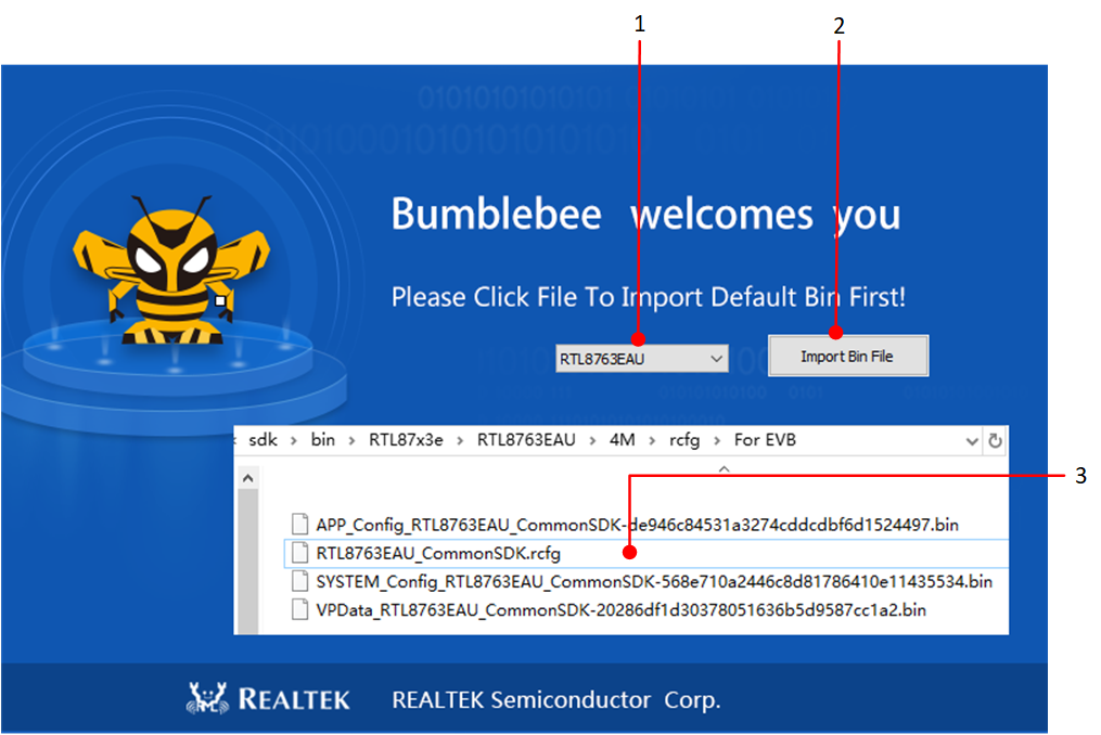
This document explains the functions, usage and settings of MCUConfig Tool for Realtek Bluetooth Audio Chip (RTL87x3E/RTL87x3D/RTL87x3EP IC), the content of the article will use RTL87x3E as an example.
Configurable Bluetooth settings and peripheral control are offered by Realtek Bluetooth MCU. By using MCUConfig Tool during the development stage, the user can easily configure a number of MCU parameters.
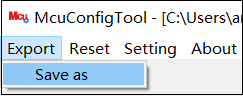
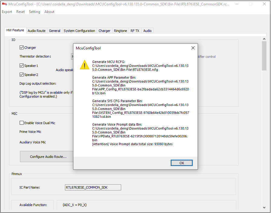
Three files will be produced, and their names and locations will be shown in a pop-up box:
RCFG File: The rcfg file will keep track of all changes made to the tool's current parameters and can be utilized for the subsequent import. It is advised to include the IC part number in the rcfg name so that other users can identify it.
APP Parameter Bin: This bin needs to be downloaded to the Bluetooth SoC.
System Configuration Parameter Bin: This bin needs to be downloaded to the Bluetooth SoC.
VP Data Parameter Bin: This bin needs to be downloaded to the Bluetooth SoC.
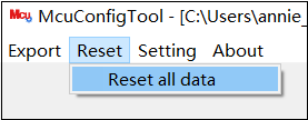
If you need to import the rcfg file again while configuring, click Reset ‣ Reset all data in the menu bar. Then, return to the main UI and select the desired rcfg file once more.
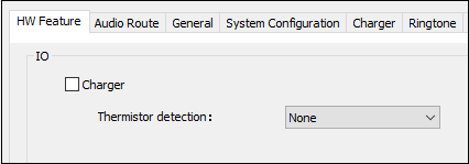
The tool's first tab, HW Feature, provides a comprehensive overview of hardware switches and PINMUX options. Some functionalities may be disabled or forbidden from configuration depending on the chip series or IC type.
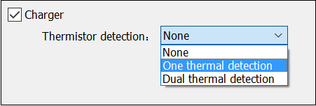
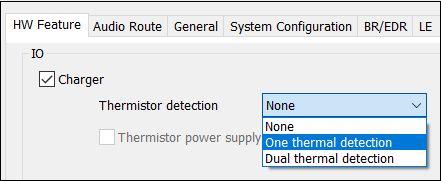
Charger: SoC has an integrated charger and a battery detecting feature. On the majority of mobile phones, you can immediately check the power of the device after connecting to the device.
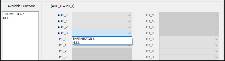
Thermistor Detection: Check the temperature of the battery. 'None' is the default selection. An external thermistor is necessary if 'One Thermal Detection' is used. Two external thermistors are needed if 'Dual Thermal Detection' is chosen.
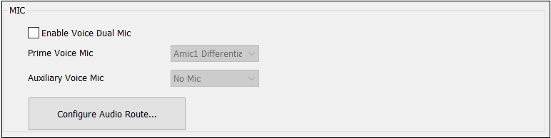
The SoC's microphone can be set up to fit particular design specifications.
Auxiliary Voice MIC options will be shown when Enable Voice Dual MIC is enabled. Depending on their needs, users can choose between analog and digital microphones.
Users can configure the required microphone in accordance with the ANC situation.
Depending on their preferences, users can choose between Low Latency APTs and Normal APTs.
Here is a list of all configurable pins and pads. The available pins vary amongst SoCs, and the available pad functions are associated with DSP and peripheral capabilities.
Charger Support: Setting the power supply's functions (can turn on charging and battery detection functions).
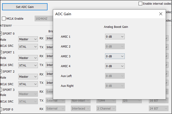
The ADC Gain is mainly used to configure the analog boost gain of the selected physical MIC or AUX. When there is a need to adjust the volume of the MIC input, it can be done through this function.
When configuring the Physical IO of a corresponding Physical MIC or AUX, also configure the ADC Gain of that Physical MIC or AUX. For example, if the Voice Primary In is configured in the Voice Category and AMIC1 is selected, then the ADC Gain value of AMIC1 should be configured.
MICADC Gain can be adjusted using the Set ADC Gain button only if AMIC is selected.
AUX ADC Gain can be adjusted by setting the Set ADC Gain button only when AUX is selected.
DMIC Gain cannot be adjusted by the Set ADC Gain button.
Configure ADC Gain for the AMIC index as required.
MCLK is mainly used to configure the master clock of the external device, e.g. PA, DAC and DSP. When the Codec in SPORTs block is configured for External selection, you need to configure the MCLK related configuration here.
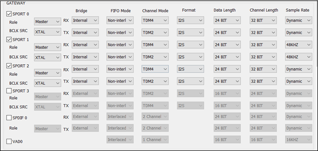
In the current Gateway parameters, the SPORT and SPDIF hardware parameters are configured by default. Unless there are specific requirements, there is no need to set the SPORT and SPDIF hardware parameters.
If customers require the configuration of the SPORT and SPDIF parameters, they should contact the relevant developer to obtain and provide the necessary parameters.
The default configuration for SPORT and SPDIF may vary depending on the specific IC.
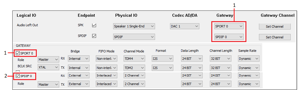
SPORT 0/1/2/3: Select this option to enable the SPORT of the corresponding index. If the Gateway ID of an Audio Route path is selected, enable this Gateway ID and configure related parameters. The figure shows when to configure Gateway ID parameters.
SPDIF0: Select this option to enable the SPDIF of the corresponding index.
VAD0: Select this option to enable the VAD of the corresponding index.
Bridge: SPORT supports single-direction TX and RX configurations. The options are internal and external. It is worth noting that when this option is configured as external, go to the HW Feature tab to configure the corresponding PINMUX.
Role: Configure the SPORT role. The value can be master or slave.
BCLK SRC: Configure the SPORT bclk and jitter functions. The optional value is XTAL/PLL.
RX/TX FIFO Mode: Configure the manner in which the RX and TX directions of SPORT align FIFO data. The optional value is Non-interlaced/Interlaced.
RX/TX Channel Mode: Configure the transfer mode in the RX and TX directions. The value is TDM2/4/6/8.
RX/TX Format: Configure the data format of the TX and RX directions of the SPORT. The optional values are I2S/Left Justified/PCM_A/PCM_B.
RX/TX Data Length: Configure the data length in the TX and RX directions of the SPORT. The optional values are 8/16/20/24/32BIT.
RX/TX Channel Length: Configure the channel length in the RX and TX directions of the sport. The optional value is 16/20/24/32BIT.
RX/TX Sample Rate: Configure the RX and TX direction of SPORT support sampling rate conversion, optional value of 8/16/32/44.1/48/88.2/96/192/12/24/11.025/22.05KHz.
If there are special requirements, the following check boxes can be configured. If the 'DAC1' check box is selected in 'DAC0', it allows for the mixing of data from DAC_R to DAC_L.
Note that DAC_L corresponds to DAC0, while DAC_R corresponds to DAC1. Enabling the 'DAC0' check box in 'DAC1' allows for the mixing of data from DAC_L to DAC_R.
When there is a requirement to reduce the latency of the DAC Channel, Codec Interpolation Filter Type should be configured. Each Codec DAC channel can choose either linear or minimum interpolation filter type.
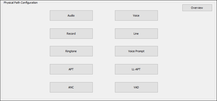
Audio Logic Device supports the configuration of Logic IO parameters for data streams such as Audio, Voice, Record, Line, Ringtone, Voice Prompt, APT, LLAPT, ANC and VAD.
The Logical IO configuration of each category is different for TWS and Headset.
If there is a need to configure the Logical IO parameter for the Audio Category, the appropriate Audio Category button should be clicked. The corresponding configuration box will then pop up.
It should be noted that the Logical IO configuration is different for different product forms. This section explains how to configure Logical IO in terms of TWS and Headset. The Overview button can be clicked.
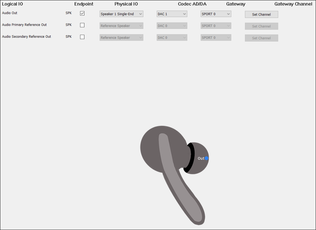
As shown in the figure, this line of configuration for Audio Out forms an Audio Route path. When clicking the blue dot in the TWS headphone diagram, the Audio Out will be bolded to indicate that it's necessary to configure the Audio Route path in order to play the audio sound.
Check the box on the Endpoint to enable Audio Out.
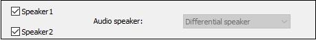
For Physical IO, select Speaker1/2 Single-end/Differential.
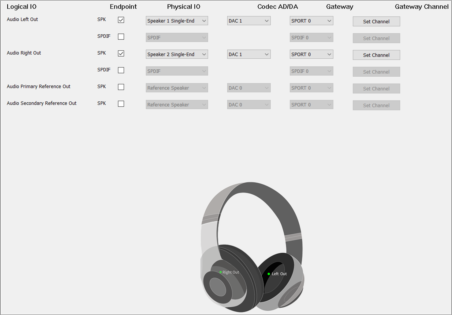
The figure shows how to configure Audio Route path for Audio Category of Headset.Different from TWS, Headset needs to select Audio Primary Out and Audio Secondary Out.
For Audio Secondary Out, the DAC Channel should be set to DAC1 and the Gateway Channel should be set to TX Channel 1. AEC Loopback AEC means linear removal of echo signal mixing in microphone input without affecting the quality of the desired speech signal.
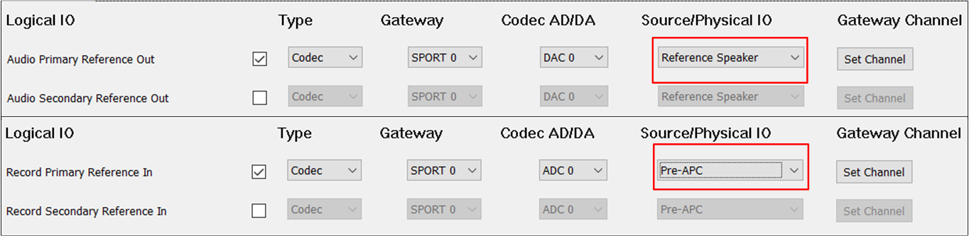
To enable the AEC loopback function, check the Audio Primary Reference Out or Audio Secondary Reference Out.
For Physical IO of Audio Primary Reference Out and Audio Secondary Reference Out, select Reference Speaker.
When the Record Primary Reference In and Record Secondary Reference In corresponding to the Record Category are also configured, the AEC loopback path of Audio and Record can be really connected.
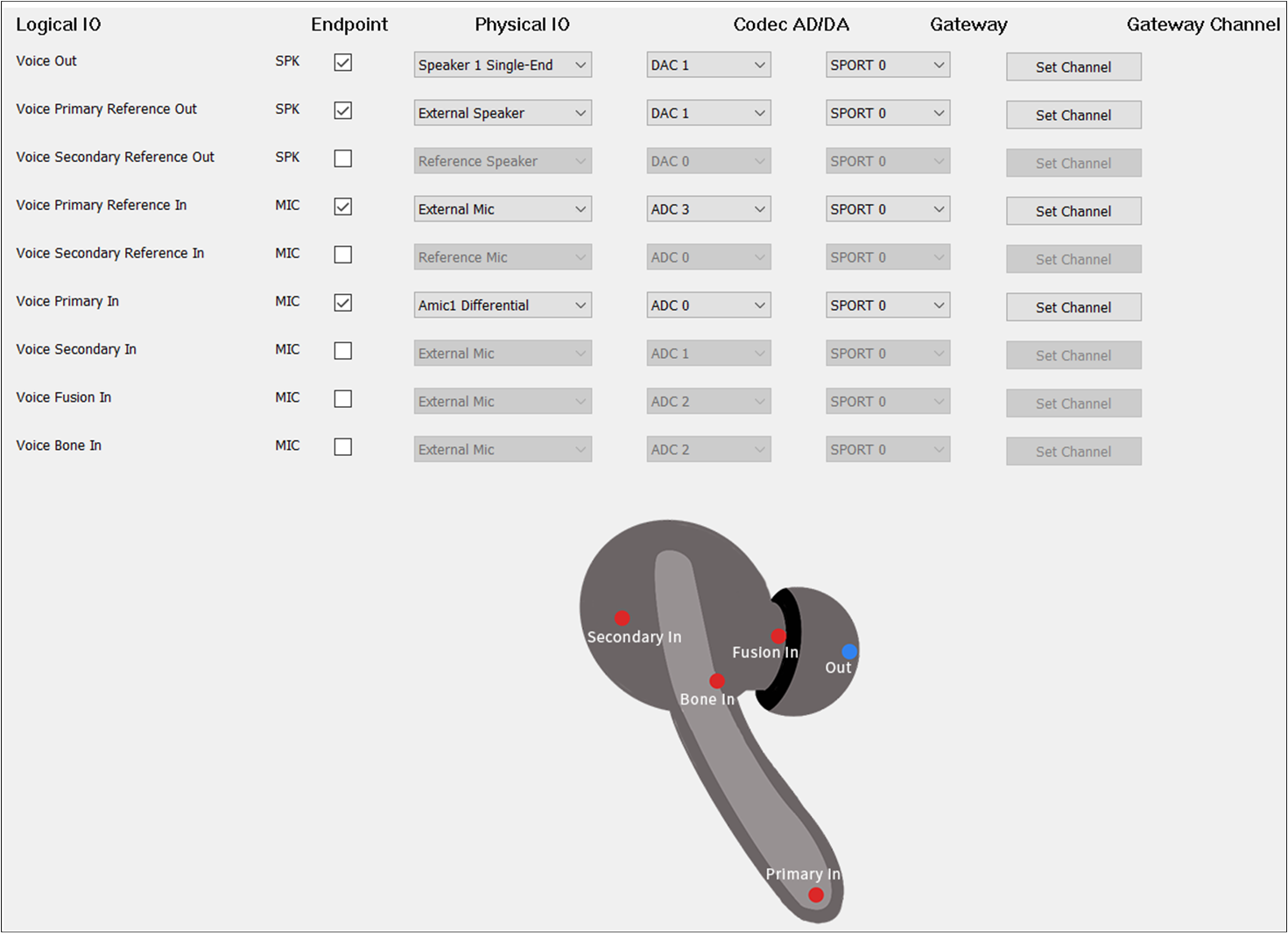
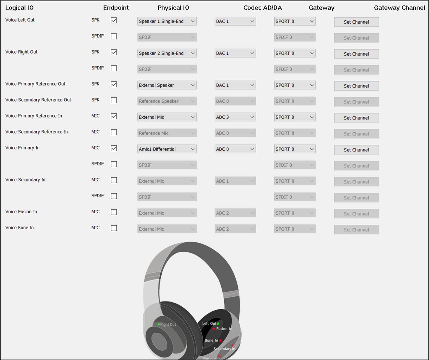
The figure shows how to configure an Audio Route path for Voice Out of TWS. Voice Out should be selected. The Voice Out parameters are the same as the Audio Out parameters.
The figure shows how to configure an Audio Route path for the Voice Category of Headset. Different from TWS, Headset needs to select Voice Primary Out and Voice Secondary Out.
For Voice Secondary Out, the DAC Channel should be set to DAC1 and the Gateway Channel should be set to TX Channel 1.
If there is no special requirement, the Voice Primary In should be selected to play the input voice. For Endpoint, check the MIC button to enable Voice Primary In.
For Physical IO, select the index and type of MIC. For ADC Channel, select ADC0/1/2/3/4/5. For Gateway, select SPORT0.
For Gateway Channel, select RX Channel 0/1/2/3. It should be noted that the ADC Channel and Gateway Channel should choose a different index for different Logical IO.
Dual MIC when two microphones are needed as input, select Voice Primary In and Voice Secondary In. It should be noted that the ADC Channel and Gateway Channel of Voice Primary In and Voice Secondary In should be different.
For example, when the ADC Channel of Voice Primary In is set to ADC0, the ADC Channel of Voice Secondary In should be set to ADC1/2/3/4. The Gateway Channel of Voice Primary In is set to RX Channel 0, the Gateway Channel of Voice Secondary In should be set to RX Channel 1/2/3/4.
Audio effect requirements when other voice sound effects requirements arise, Voice Fusion In and Voice Bone In can be configured. Similarly, the ADC Channel and Gateway Channel of Voice Fusion In and Voice Bone In should be different from Voice Primary In and Voice Secondary In.
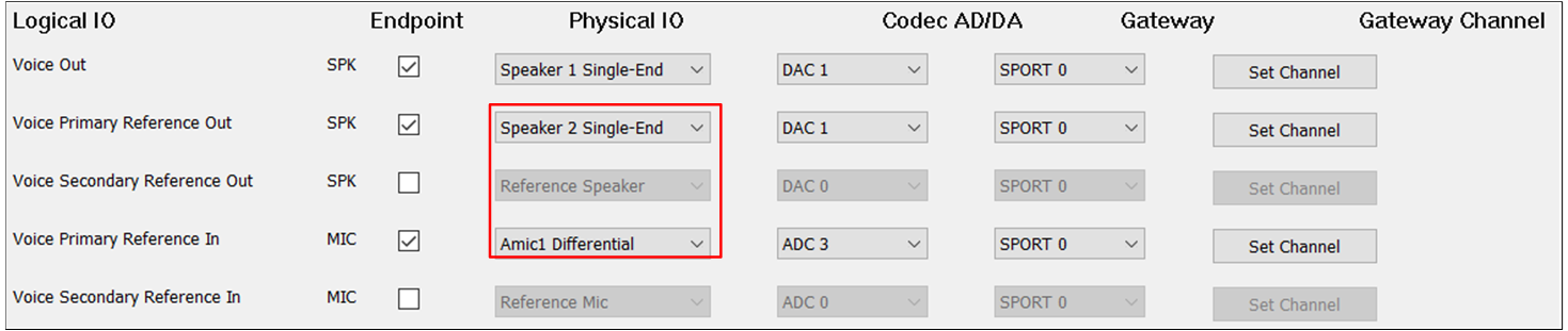
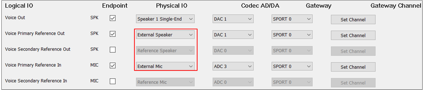
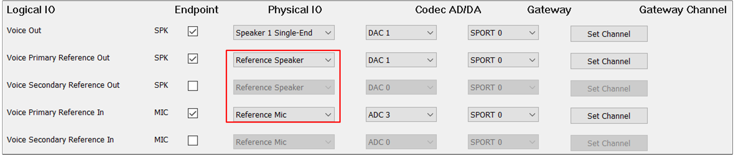
When there is a requirement for AEC loopback functionality, select the Voice Primary Reference Out and Voice Primary Reference In at the same time. The Voice Secondary Reference Out and Voice Secondary Reference In can also be selected at the same time to enable the AEC loopback functionality.
For Physical IO of Voice Reference Primary Out and Voice Reference Secondary Out, select Reference Speaker.
For DAC Channel of Voice Reference Primary Out and Voice Reference Secondary Out, select DAC0 or DAC1.
For Physical IO of Voice Reference Primary In and Voice Reference Secondary In, select Reference MIC. It should be noted that the ADC Channel and Gateway Channel should choose a different index for different Logical IO.
When the Voice Primary Reference Out and Voice Primary Reference In corresponding to the Voice Category, or when the Voice Secondary Reference Out and Voice Secondary Reference In are configured, the AEC loopback path is actually connected.
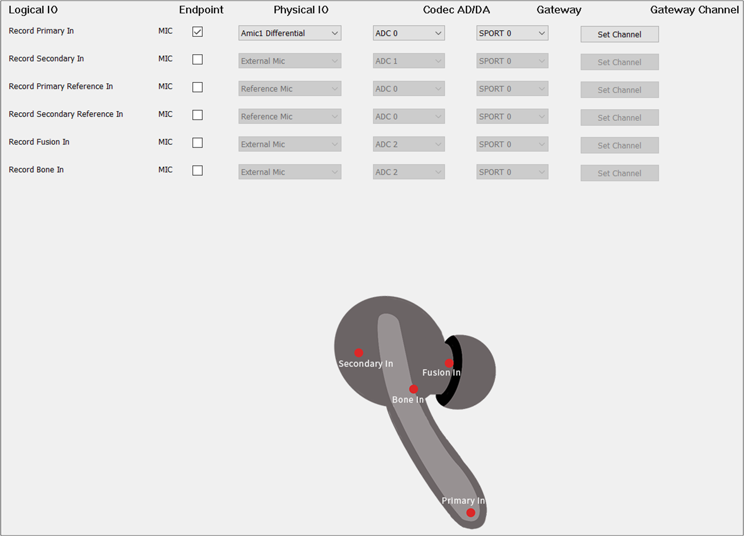
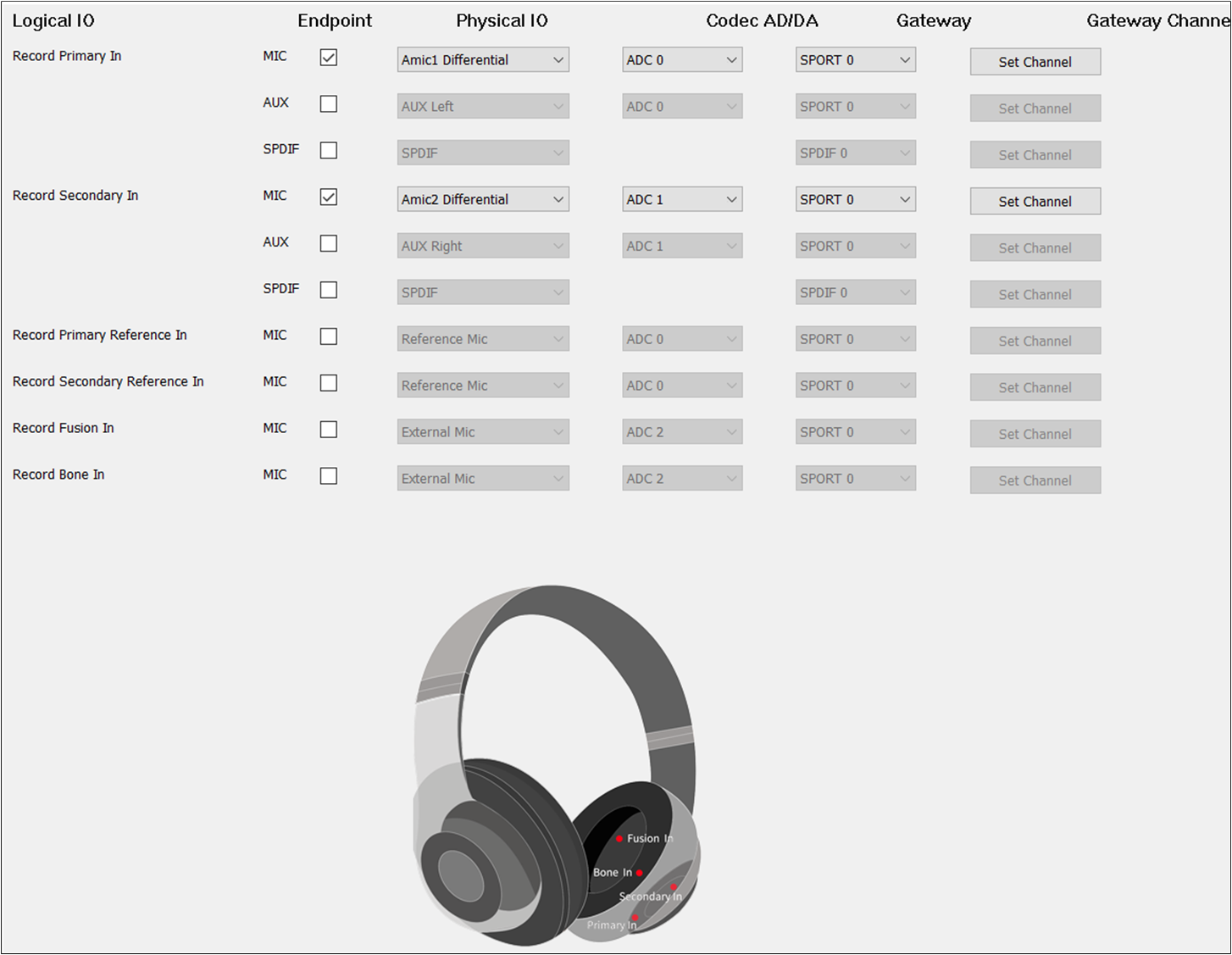
Record Category supports Record Primary In, Record Secondary In, Record Primary Reference In, Record Secondary Reference In, Record Fusion In, and Record Bone In:
Record Primary In is used to set the Record physical route of the Primary input endpoint.
Record Secondary In is used to set the Record physical route of the Secondary input endpoint.
Record Primary Reference In is used to set the Record physical AEC loopback path of the Primary input endpoint.
Record Secondary Reference In is used to set the Record physical AEC loopback path of the Secondary input endpoint.
Record Fusion In is used to set the Record physical route of the Fusion input endpoint.
Record Bone In is used to set the Record physical route of the Bone Sensor input endpoint.
If there is no special requirement, the Record Primary In should be selected to record the input sound. For Endpoint, check the MIC button to enable Record Primary In.
For Physical IO, select the index and type of MIC. For ADC Channel, select ADC0/1/2/3/4/5.
For Gateway, select SPORT0. For Gateway Channel, select RX Channel 0/1/2/3. It should be noted that the ADC Channel and Gateway Channel should choose a different index for different Logical IO.
When two microphones are needed as input, check Record Primary In and Record Secondary In. It should be noted that the ADC Channel and Gateway Channel of Record Primary In and Record Secondary In should be different.
When other voice sound effects are required, configure Record Fusion In and Record Bone In. The ADC Channel and Gateway Channel of Record Fusion In and Record Bone In should also be different from each other.
When the AEC loopback functionality is required, check the Audio Primary Reference Out and Record Primary Reference In at the same time. Also, check the Audio Secondary Reference Out and Record Secondary Reference In at the same time to enable the AEC loopback functionality.
The ADC Channel and Gateway Channel of Record Primary Reference In and Record Secondary Reference In should also be different from Record Primary In, Record Secondary In, Record Fusion In and Record Bone In if they are selected.
When the Primary Reference SPK and Secondary Reference SPK corresponding to Audio Category, Ringtone Category or Voice Prompt Category are configured, the AEC loopback path for Audio and Record, Ringtone and Record, or Voice Prompt and Record is open.
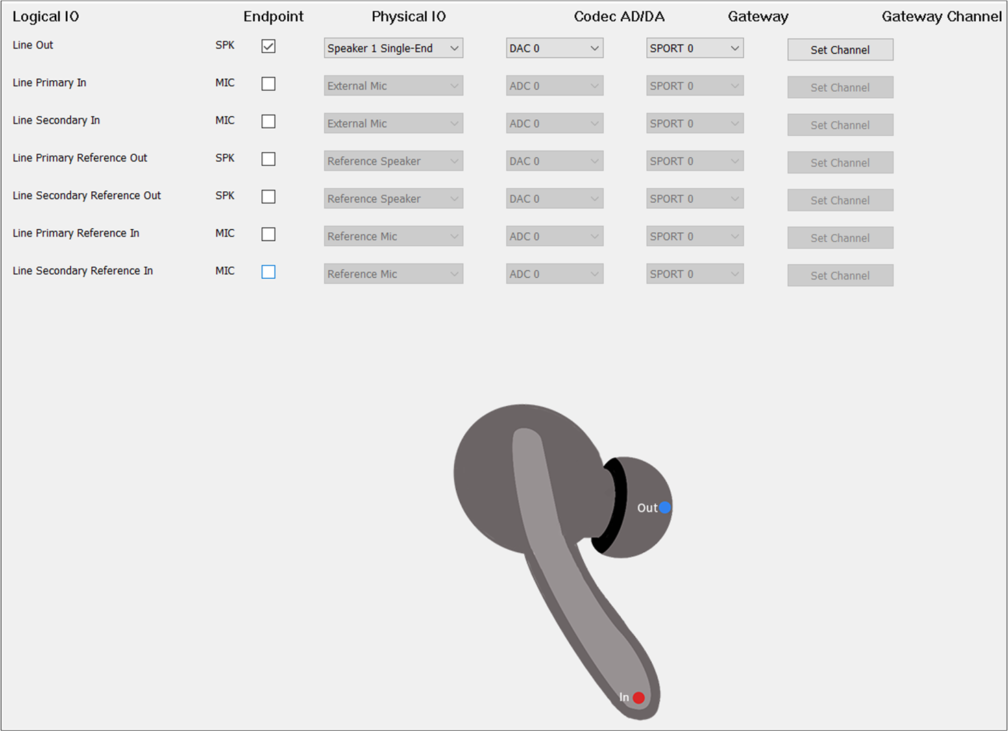
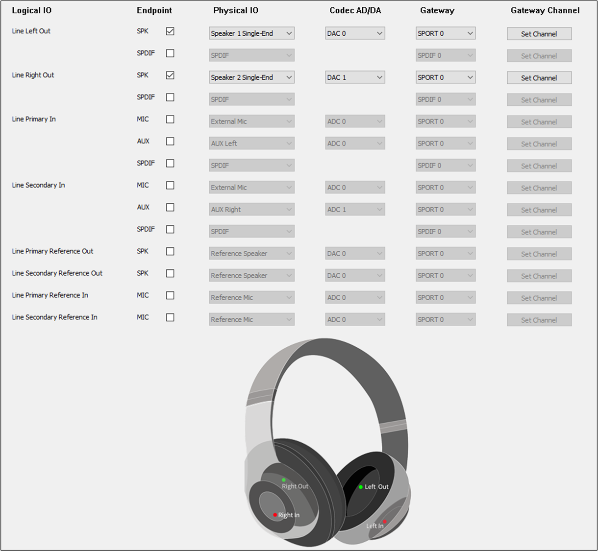
Line Category supports Line Primary Out, Line Secondary Out, Line Primary Reference Out, Line Secondary Reference Out, Line Left In, Line Right In, Line Primary Reference In and Line Secondary Reference In:
Line Primary Out is used to set the Line physical route of the Primary output endpoint.
Line Secondary Out is used to set the Line physical route of the Secondary output endpoint.
Line Primary Reference Out is used to set the Line physical AEC loopback path of the Primary output endpoint.
Line Secondary Reference Out is used to set the Line physical AEC loopback path of the Secondary output endpoint.
Line Primary Reference In is used to set the Line physical AEC loopback path of the Primary input endpoint.
Line Secondary Reference In is used to set the Line physical AEC loopback path of the Secondary input endpoint.
Line Primary In is used to set the Line physical route of the Primary input endpoint.
Line Secondary In is used to set the Line physical route of the Line Secondary input endpoint.
To play the sound of the Line and record the input of the Line, select Line Out and Line In. For the endpoint of Line, select AUX, and the physical IO should be set to AUX Left.
For Headset, select Line Primary Out and Line Secondary Out, Line Left In and Line Right In. The DAC Channel and Gateway Channel of Line Primary Out and Line Secondary Out are the same as Audio Primary Out and Audio Secondary Out.
The ADC Channel and Gateway Channel of Line Left In and Line Right In should be different.
When there is a requirement for AEC loopback functionality, check the Line Primary Reference Out and Line Primary Reference In at the same time. Also, check the Line Secondary Reference Out and Line Secondary Reference In at the same time to enable the AEC loopback functionality.
The ADC Channel and Gateway Channel of Line Primary Reference In and Line Secondary Reference In should also be different from Line Left In, Line Right In if they are selected.
When the Line Primary Reference Out and Line Primary Reference In corresponding to the Line Category, or when the Line Secondary Reference Out and Line Secondary Reference In are configured, the loopback path of the AEC is actually connected.
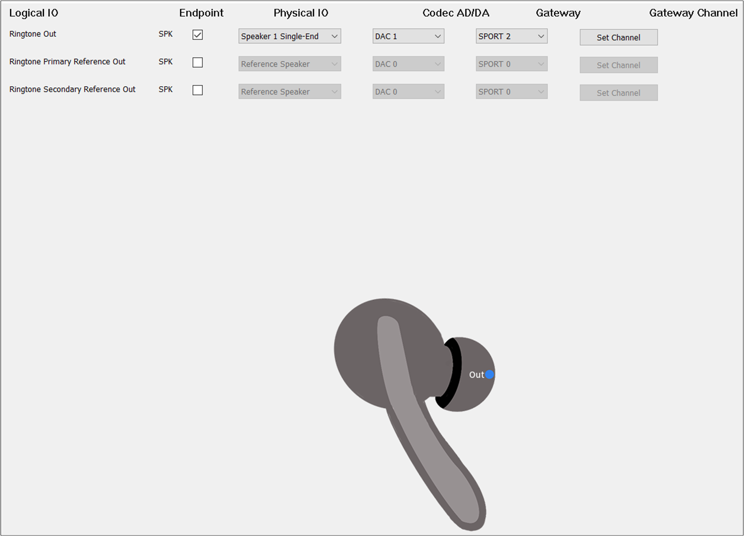
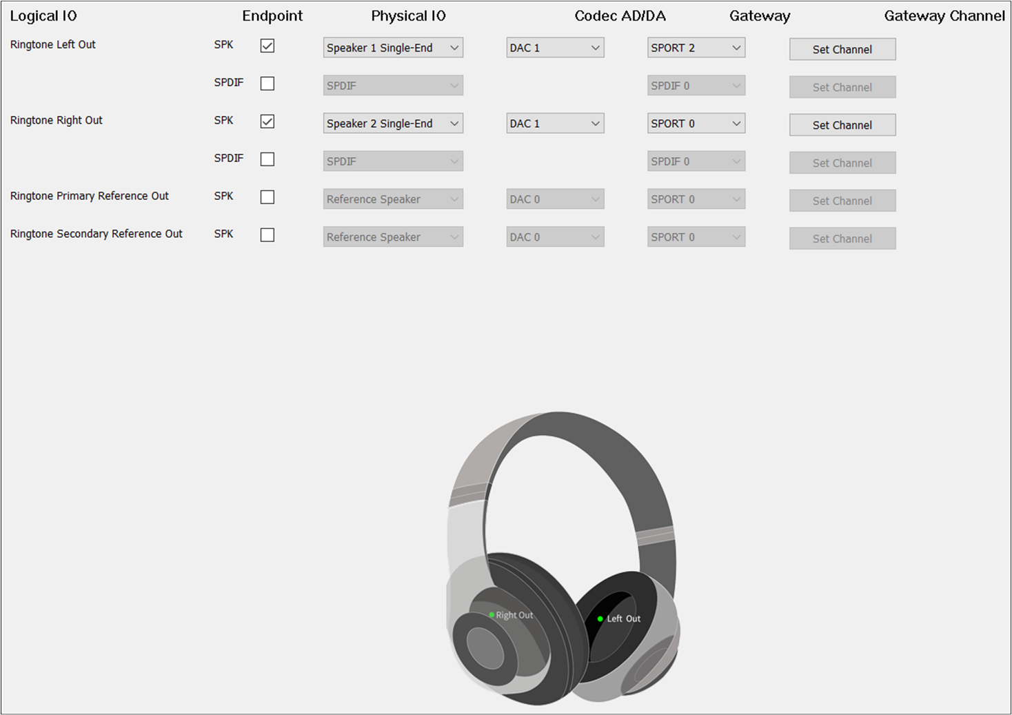
Check the box on the Endpoint to enable Ringtone Out. For Physical IO, select Speaker1/2 Single-end/Differential. For DAC Channel, select DAC2. For Gateway, select SPORT2. For Gateway Channel, select TX Channel 0.
Different from TWS, Headset needs to check Ringtone Primary Out and Ringtone Secondary Out. For Ringtone Secondary Out, the DAC Channel should be set to DAC1 and the Gateway Channel should be set to TX Channel 1.
To enable the AEC loopback function, check the Ringtone Primary Reference Out or Ringtone Secondary Reference Out.
When the Record Primary Reference In and Record Secondary Reference In corresponding to the Record Category are also configured, the AEC loopback path of Ringtone and Record is really open.
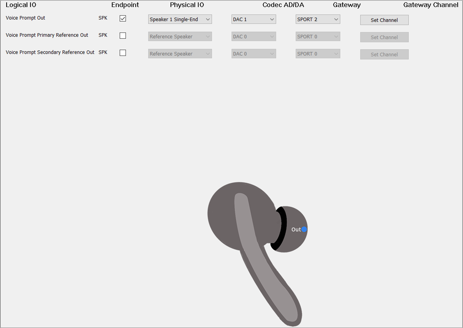
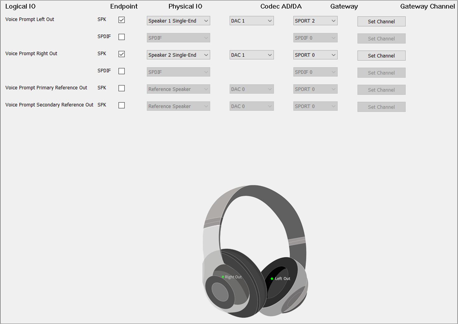
The box on the Endpoint should be checked to enable Voice Prompt Out. For Physical IO, select Speaker1/2 Single-end/Differential. For DAC Channel, select DAC2. For Gateway, select SPORT2.
Different from TWS, Headset needs to check Voice Prompt Primary Out and Voice Prompt Secondary Out. For Voice Prompt Secondary Out, set the DAC Channel to DAC1 and the Gateway Channel to TX Channel 1.
To enable the AEC loopback function, check the Voice Prompt Primary Reference Out or Voice Prompt Secondary Reference Out.
When the Record Primary Reference In and Record Secondary Reference In corresponding to the Record Category are also configured, the AEC loopback path of the Voice Prompt and the Record is reallyopen.
APT function supports APT Primary Out, APT Secondary Out, APT Primary Reference Out, APT Secondary Reference Out, APT Primary Reference In, APT Secondary Reference In, APT Front Left In, APT Front Right In, APTFF Left In and APTFF Right In, APTFB Left In, APTFB Right In, APT Bone Left In and APT Bone Right In:
APT Primary Out is used to set the APT physical route of the Primary output endpoint.
APT Secondary Out is used to set the APT physical route of the Secondary output endpoint.
APT Primary Reference Out is used to set the APT physical AEC loopback path of the Primary output endpoint.
APT Secondary Reference Out is used to set the APT physical AEC loopback path of the Secondary output endpoint.
APT Primary Reference In is used to set the APT physical AEC loopback channel of the Primary input endpoint.
APT Secondary Reference In is used to set the APT physical AEC loopback channel of the Secondary input endpoint.
APT Front Left In is used to set the APT physical route of the front Left input endpoint.
APT Front Right In is used to set the APT physical route of the front Right input endpoint.
APTFF Left In is used to set the APT physical route of the FF Left input endpoint.
APTFF Right In is used to set the APT physical route of the FF Right input endpoint.
APTFB Left In is used to set the APT physical route of the FB Left input endpoint.
APTFB Right In is used to set the APT physical route of the FB Right input endpoint.
APT Bone Left In is used to set the APT physical route of the Bone Sensor Left input endpoint.
APT Bone Right In is used to set the APT physical route of the Bone Sensor Right input endpoint.
To play the sound of APT, select the APT Out. For Physical IO, select Speaker1/2 Single-end/Differential. For DAC Channel, select DAC1. For Gateway, select SPORT1. For Gateway Channel, select TX Channel 0.
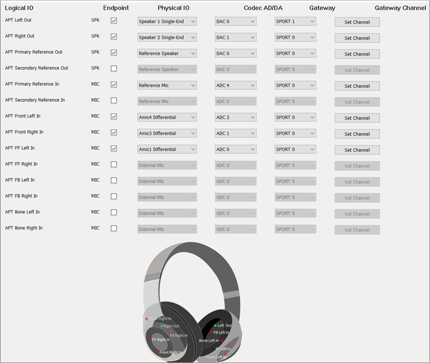
APT Primary Out and APT Secondary Out should be selected. The DAC Channel and Gateway Channel of APT Primary Out and APT Secondary Out are the same as Audio Primary Out and Audio Secondary Out.
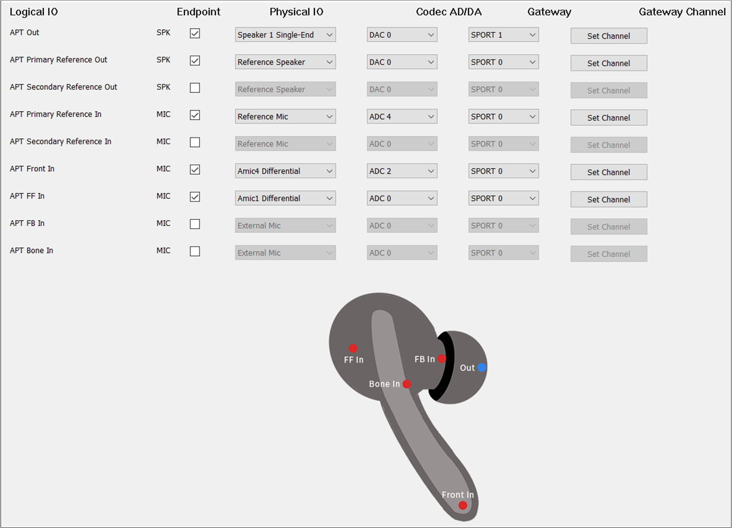
If there is no special requirement, the APT Front In should be selected to record the input sound of APT. For Endpoint, check the MIC button to enable APT Front In.
For Physical IO, select the index and type of MIC. For ADC Channel, select ADC0/1/2/3/4/5. For Gateway, select SPORT0. For Gateway Channel, select RX Channel 0/1/2/3.
When two microphones are needed as input, check APT Front In and APTFF In for TWS. For Headset, select two of APT Front Left In, APT Front Right In, APTFF Left In, APTFF Right In, APTFB Left In, and APTFB Right In.
Note that the ADC Channel and Gateway Channel of APT Front In and APTFF In should be different.
When three microphones are needed as input, check APT Front In, APTFF In, and APTFB In for TWS. For Headset, select three of APT Front Left In, APT Front Right In, APTFF Left In, APTFF Right In, APTFB Left In, and APTFB Right In.
The ADC Channel and Gateway Channel of APT Front In, APTFF In, and APTFB In should also be different from each other.
When other voice sound effects are needed, configure APT Bone In for TWS. For Headset, select APT Bone Left In or APT Bone Right In. The ADC Channel and Gateway Channel of APT Bone In should also be different from APT Front In, APTFF In, and APTFB In.
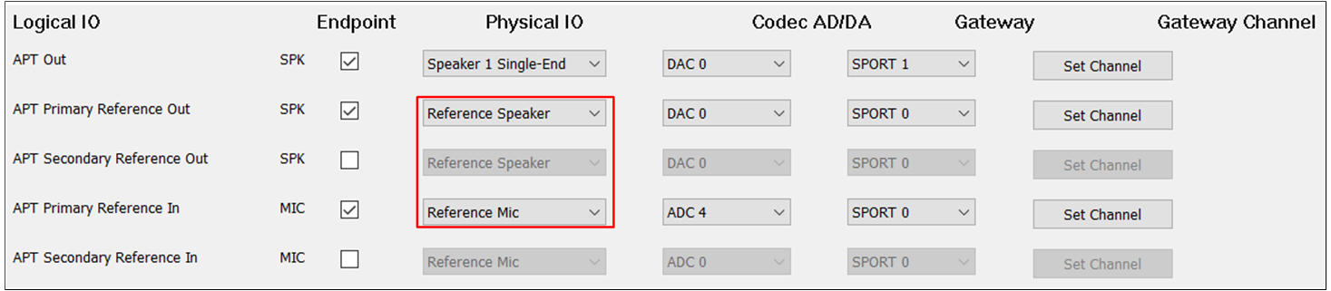
To enable the AEC loopback function, check the APT Primary Reference Out and APT Primary Reference In. Select APT Secondary Reference Out and APT Secondary Reference In.
When APT Primary Reference Out and APT Primary Reference In correspond to APT Category, or when APT Secondary Reference Out and APT Secondary Reference In are configured, the AEC loopback path can be really opened.
LLAPT function supports LLAPT Primary Out, LLAPT Secondary Out, LLAPT Primary Reference Out, LLAPT Secondary Reference Out, LLAPT Primary Reference In, LLAPT Secondary Reference In, LLAPT Left In, and LLAPT Right In:
LLAPT Primary Out is used to set the LLAPT physical route of the Primary SPK.
LLAPT Secondary Out is used to set the LLAPT physical route of the Secondary SPK.
LLAPT Primary Reference Out is used to set the LLAPT physical AEC loopback path of the Primary SPK.
LLAPT Secondary Reference Out is used to set the LLAPT physical AEC loopback path of the Secondary SPK.
LLAPT Primary Reference In is used to set the LLAPT physical AEC loopback path of the Primary MIC.
LLAPT Secondary Reference In is used to set the LLAPT physical AEC loopback path of the Secondary MIC.
LLAPT Left In is used to set the LLAPT physical route of the Left MIC.
LLAPT Right In is used to set the LLAPT physical route of the Right MIC.
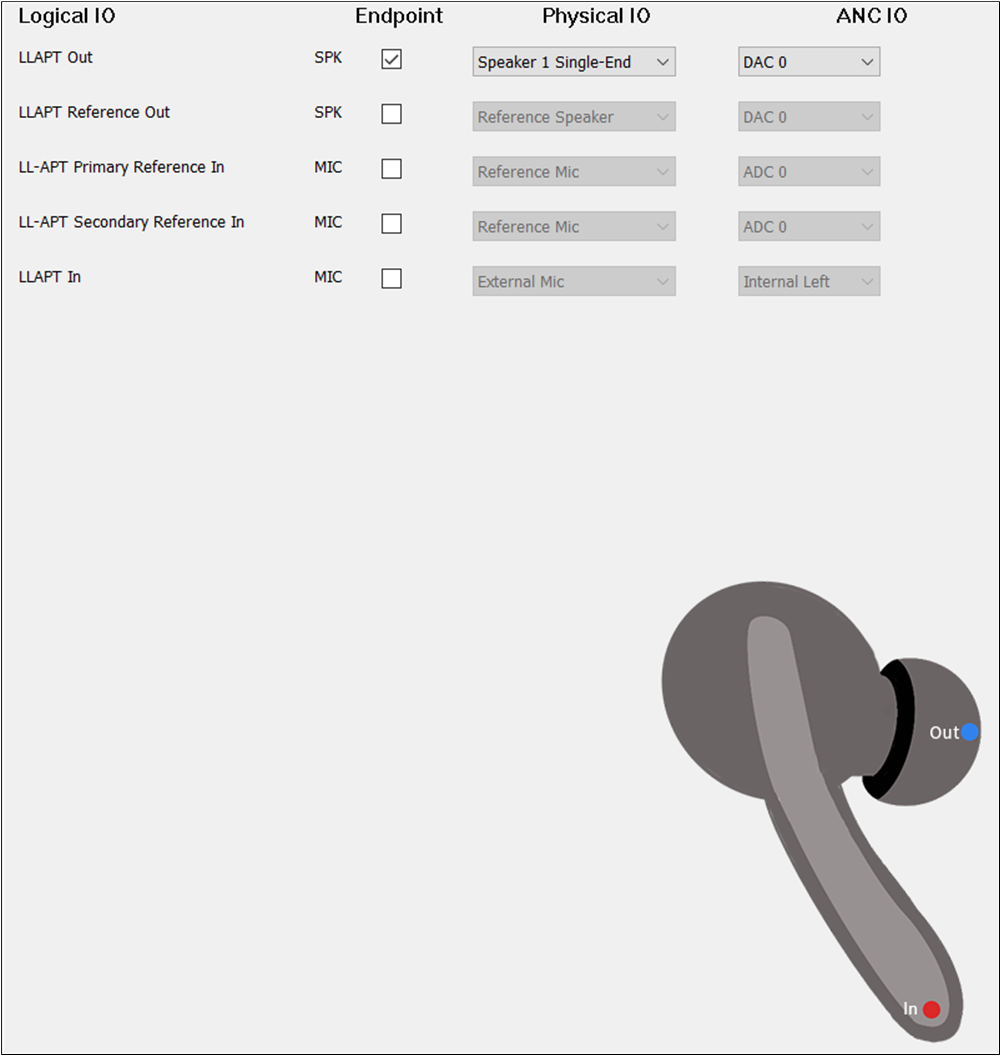
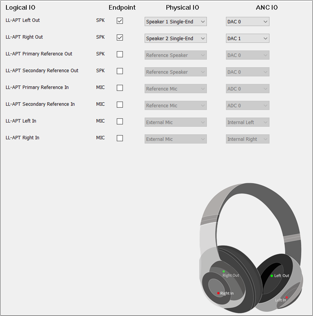
To play the sound of LLAPT, select the LLAPT Out. The configuration of LLAPT Out could be the same as Audio Out. To record the input sound of LLAPT, select the LLAPT In. For the ANC IO of LLAPT, select External Left, External Right, Internal Left, and Internal Right.
But for LLAPT In, the ANC IO must be set to External Right for TWS.
LLAPT Primary Out and LLAPT Secondary Out should be checked. The DAC Channel and Gateway Channel of LLAPT Primary Out and LLAPT Secondary Out are the same as Audio Primary Out and Audio Secondary Out. LLAPT Left In and LLAPT Right In should be selected.
The ANC IO and Gateway Channel of LLAPT Left In must be different from LLAPT Right In. The ANC IO of LLAPT Left In must be set to External Left. The ANC IO of LLAPT Right In must be set to External Right.
To enable the AEC loopback function, check the LLAPT Primary Reference Out and LLAPT Primary Reference In. Select LLAPT Secondary Reference Out and LLAPT Secondary Reference In.
When LLAPT Primary Reference Out and LLAPT Primary Reference In correspond to LLAPT Category, or when the LLAPT Secondary Reference Out and LLAPT Secondary Reference In are configured, the AEC loopback path can be really connected.
ANC Category supports ANC Primary Out, ANC Secondary Out, ANC Primary Reference Out, ANC Secondary Reference Out, ANC Primary Reference In, ANC Secondary Reference In, ANCFF Left In, ANCFF Right In, ANCFB Left In and ANCFB Right In:
ANC Primary Out is used to set the ANC physical route of the Primary SPK.
ANC Secondary Out is used to set the ANC physical route of the Secondary SPK.
ANC Primary Reference Out is used to set the ANC physical AEC loopback path of the Primary SPK.
ANC Secondary Reference Out is used to set the ANC physical AEC loopback path of the Secondary SPK.
ANC Primary Reference In is used to set the ANC physical AEC loopback path of the Primary MIC.
ANC Secondary Reference In is used to set the ANC physical AEC loopback path of the Secondary MIC.
ANCFF Left In is used to set the ANC physical route with the Feedforward Left MIC.
ANCFF Right In is used to set the ANC physical route with the Feedforward Right MIC.
ANCFB Left In is used to set the ANC physical route of the Feedback Left MIC.
ANCFB Right In is used to set the ANC physical route of the Feedback Right MIC.
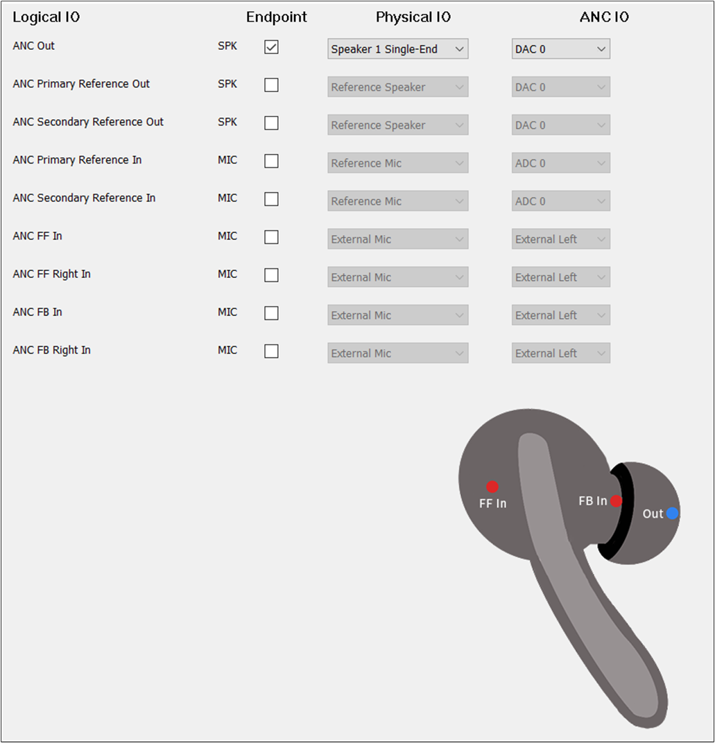
To play the sound of ANC, select the ANC Out. The configuration of ANC Out could be the same as Audio Out. To record the input sound of ANC, there are three scenarios. Configure it according to requirements.
Only select ANCFF In. Only select ANCFB In. Select ANCFF In and ANCFB In together.
For the ANC IO of ANC, select External Left, External Right, Internal Left, and Internal Right. But for ANCFF In, the ANC IO must be set to External Left for TWS. For ANCFB In, the ANC IO must be set to Internal Right.
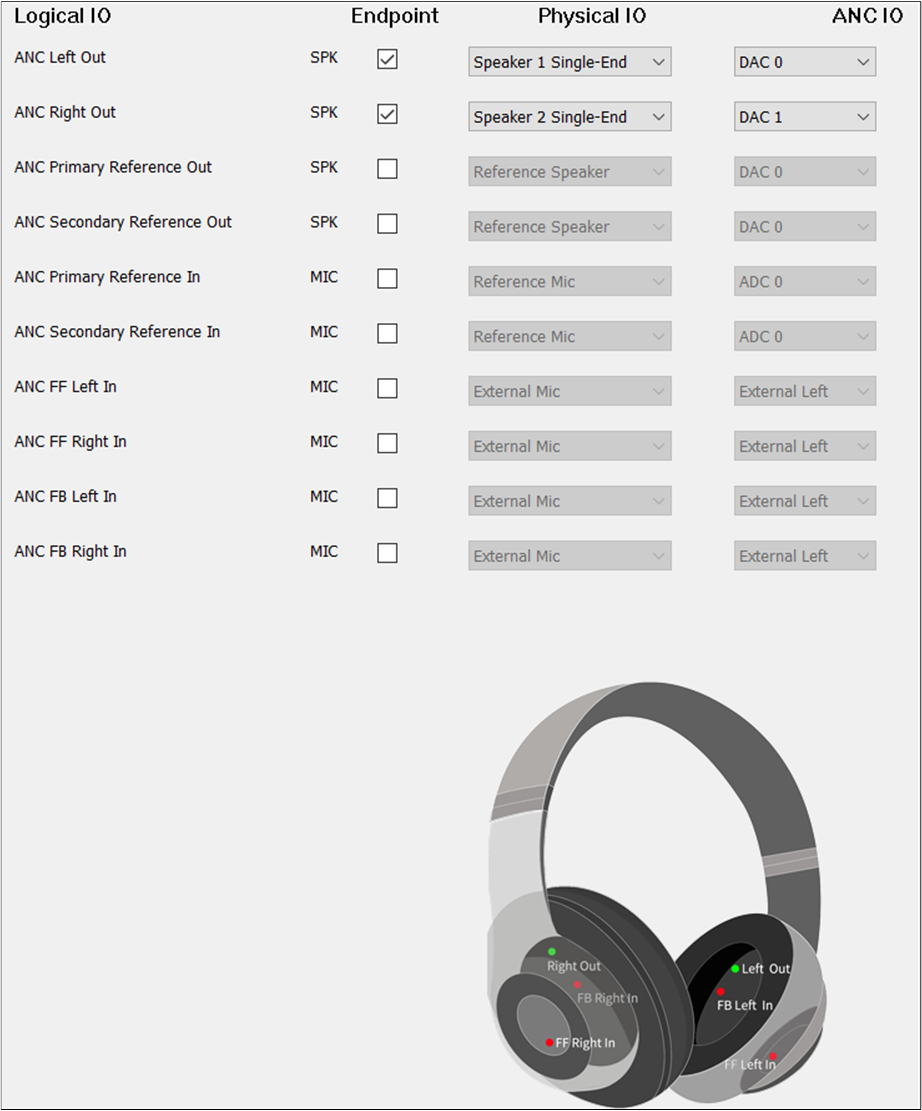
ANC Primary Out and ANC Secondary Out should be checked. The DAC Channel and Gateway Channel of ANC Primary Out and ANC Secondary Out are the same as Audio Primary Out and Audio Secondary Out.
ANCFF Left In and ANCFF Right In should be selected. ANCFB Left In and ANCFB Right In should be selected. The ANC IO and Gateway Channel of LLAPT Left In must be different from LLAPT Right In.
The ANC IO of ANCFF Left In must be set to External Left. The ANC IO of ANCFF Right In must be set to External Right.
The ANC IO of ANCFB Left In must be set to Internal Left. The ANC IO of ANCFB Right In must be set to Internal Right.
When enabling the AEC loopback function, check the ANC Primary Reference Out and ANC Primary Reference In. It is also possible to select ANC Secondary Reference Out and ANC Secondary Reference In.
When ANC Primary Reference Out and ANC Primary Reference In correspond to ANC Category, or when the ANC Secondary Reference Out and ANC Secondary Reference In are well configured, the AEC loopback path can be really opened.
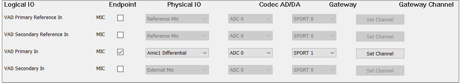
If there is no special requirement, the VAD Primary In should be selected to record the input sound. For Endpoint, check the MIC button to enable VAD Primary In. For Physical IO, select the index and type of microphone.
For ADC Channel, select ADC0/1/2/3/4/5. For Gateway, select SPORT0. For Gateway Channel, select RX Channel 0/1/2/3. It should be noted that the ADC Channel and Gateway Channel should choose a different index for different.
When two microphones are needed as input, check VAD Primary In and VAD Secondary In. It should be noted that the ADC Channel and Gateway Channel of VAD Primary In and VAD Secondary In should be different.
When there is a requirement for AEC loopback functionality, check the Audio Primary Reference Out and VAD Primary Reference In at the same time.
The Audio Secondary Reference Out and VAD Secondary Reference In can also be checked to enable the AEC loopback functionality.
The ADC Channel and Gateway Channel of VAD Primary Reference In and VAD Secondary Reference In should also be different from VAD Primary In, VAD Secondary In if they are selected.
When the Primary Reference SPK and Secondary Reference SPK corresponding to Audio Category, Ringtone Category, or Voice Prompt Category are configured, the AEC loopback path for Audio and VAD, Ringtone and VAD, or Voice Prompt and VAD is open.
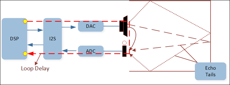
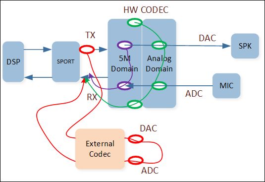
AEC Reference Function: Linear removal of echo signal mixing in microphone input without affecting the quality of the desired speech signal. For UI configuration, when there is a need to configure the AEC Reference function, select Primary Reference Out and Primary Reference in of Audio Category. The AEC Reference configuration can be performed in the following three cases:
Case2: Reference signal from HW Codec DAC[5M] => DAC[Analog] => ADC[5M] => SPORT RX => DSP.
In this case, for UI configuration, select Primary Reference Out and set them to physical speaker and select Primary Reference In and set them to physical microphone.
The name shown on the user's Bluetooth device, including both the LE name and the legacy name. The device name has a maximum length of 40 bytes and is encoded in UTF-8.
DMIC 1/2: When digital microphone is chosen in Audio Route, set the clock rate of DMIC 1/2, which can be configured as 312.5KHz/625KHz/1.25MHz/2.5MHz/5MHz clock rate.
MICBIAS Voltage: Adjust the MICBIAS output voltage according to the specifications of the MIC, it can be configured as 1.44V/1.62V/1.8V when AVCCDRV is 1.8V, and the default is 1.62V. It can be configured as 1.8V/1.9V/2V/2.1V when AVCCDRV is 2.1V, and the default is 2.1V.
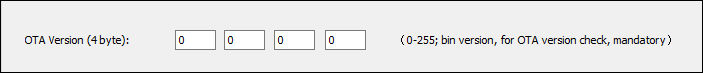
OTA Version: Setting the OTA Version for the exported APP parameter configuration bin is advised. OTA will do version comparison and APP parameter configuration bin verification. The MPPG Tool, Pack Tool, and OTA Tool all display the version number. OTA Version defaults to 0.0.0.0 if not explicitly set.
BTE Task Size: The stack size of upperstack task in the bluetooth chip, the valid value is 0~5*1024 bytes.
BR/EDR Host
BR/EDR Link Number: The maximum simultaneous number of BR/EDR links. If you select the maximum of three devices for Multi-link support, the first device will be disconnected in order to make room for the third device. If not, one of the initial two connected devices must be disconnected before the third device can be connected.
BR/EDR L2CAP Channel Number: The maximum number of L2CAP channels that can be created simultaneously. Valid numbers are 0~24.
BR/EDR Bond Device Number: The number of BR/EDR devices that will store bond information in flash. This number shall not be less than the BR/EDR link number and shall be less than or equal to 8.
Bluetooth LE Host
LE CCCD Count: The maximum number of CCCDs that can be stored in flash.
LE CCCD Per Link Count: Set the number of CCCDs supported by each Bluetooth LE link, ranging from 0 to 50.
LE GATT Max Service Attribute Table Count: LE GATT Max Service attribute table count is GATT MAX service attribute table count supported in upperstack. If APP call server_init(server_num), server_nummust<=(gatt_max_attribute_table_count-2).
LE L2CAP Channel Number: Max LE L2CAP channel number.
LE ATT over BR/EDR: ATT transport through BR/EDR.
LE ATT Max MTU Size: ATT max MTU size supported in upperstack.
LE EATT: EATT transport support.
LE EATT over BR/EDR: EATT transport through BR/EDR.
LE GATT Channel Number: Max GATT channel number, LE GATT channel number >= LE GATT ACL number.
LE GATT BR/EDR Information Storage: Storage GATT BR/EDR information.
LE GATT Caching Server: Enable/Disable GATT Caching.
LE ATT Max MTU Size: ATT max MTU size supported in upperstack. Range(23,512).
Bluetooth Controller
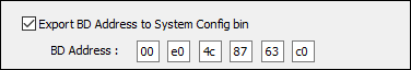
BD Address: The Bluetooth address of the device. The bluetooth address setting is only available when Export BD Address to System configuration bin is checked and then address will be in the exported system configuration bin.
LE Only Mode: Whether the LE-only functionality can be used by the bluetooth chip. This setting needs to be disabled if audio functionality is desired.
For system 32K related settings, please refer to the following descriptions for the details of the fields (the setting interface of different Chip Series or IC models is different):
AON 32K CLK SRC: 32k clock source of AON FSM. Optional external 32k XTAL, internal RCOSC SDM, external GPIO IN. Different SoCs may have different options available.
RTC 32K CLK SRC: 32k clock source of User RTC. Optional external 32k XTAL, internal RCOSC SDM, external GPIO IN. Different SoCs may have different options available.
BTMAC 32K CLK SRC: 32k clock source of BTMAAC. Selectable internal RCOSC SDM, external GPIO IN, external 32k XTAL.
SysTick 32K CLK SRC: The 32k clock source of SysTick. Selectable internal RCOSC SDM, external GPIO IN, external 32k XTAL.
BTMAC, SysTick 32K CLK SRC: 32k clock source of BTMAC/SysTick. Choice of external 32k XTAL or internal RCOSC SDM.
GPIO OUT 32K CLK SRC: 32k clock source of GPIO out. Selectable internal RCOSC SDM, external GPIO IN, external 32k XTAL.
EXT32K Frequency: The frequency of the external 32k clock source. 32.768KHz or 32KHz selectable.
EXT32K GPIO Frequency: The frequency of the external 32k GPIO clock source. 32.768KHz or 32KHz selectable.
EXT32K XTAL Frequency: The frequency of the external 32k XTAL clock source. 32.768KHz or 32KHz selectable.
RTC 32K OUT PIN: 32k GPIO output pin selection. Can choose Disable, P1_2, P2_0.
GPIO 32K OUT PIN: 32k GPIO output pin selection. Can choose Disable, ADC_7, 32K_XO, P3_4, P4_1, P6_1.
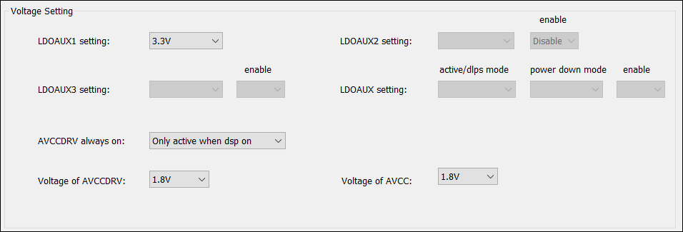
LDOAUXx Setting: Used to set the voltage. If you need to have different voltage settings according to different power modes, the voltage setting fields of different power modes will be displayed as shown in the figure above.
For example: the fields of active/dlps mode and power down mode in LDOAUX setting Whether LDOAUXx is enabled according to IO. If it is set to 'Enable', it will open LDO_AUX2 to the specified voltage (1.8V or 3.3V). If there is no such field, it means that this LDO cannot be closed.
AVCCDRV Always On: Used to set whether AVCCDRV needs to be always on, or only open when there is an audio behavior.
Voltage of AVCCDRV/AVCC: AVCC_DRV/AVCC voltage setting, which can be set to 1.8V/1.8V or 2.1V/2.0V according to the usage of peripherals.
Log Output PINMUX: Configure the pin for log output.
Log UART HW Flow Ctrl: The default log UART hardware flow control is disabled. To enable log UART hardware flow control, you must select the available log UART cts PINMUX, connect the log UART cts PINMUX to the FT232 log UART RTS pin, and set the Flow Control in the log setting of the Debug Analyzer to RequestToSend.
Enable SWD: Open the SWD debug interface.
Reset When Hardfault: When the platform Hardfault appears, the platform will automatically restart.
Watchdog Timeout: Configure watchdog timeout.
WDG Enable in ROM: Allow WDG to be enabled in ROM.
WDG Auto Feed in ROM: Automatically feed the dog in the ROM.
Max SW Timer Number: The maximum number of software timers.
Watchdog Mode: The mode after wdg timeout (reset or enter irq to print out the current status).
Charger Auto Enable: To decide the device will go into chrger mode automatically or not when adapter in, the default is 'YES', please do not modify it unless you have already contacted with the FAE and fully understand how to enable the charger with 'NO' setting.
Set Charger Configuration to APP Configuration: If the check box is set, all the charger configuration parameters will be added to the APP parameter configuration bin. And the charger firmware will apply the params in the APP parameter configuration bin instead of the system configuration bin. So that the charger parameters could be updated through OTA.
Pre-Charge Timeout (min): Battery pre-charge mode time out parameter, the range is 1-65535min.
Pre-Charge Voltage (mV): Pre-charge mode to fast-charge mode voltage threshold.
Fast-charge State Timeout (min): Battery fast charge mode (CC+CV mode) time out parameter, the range is 3-65535 min.
Charge Current of Pre-Charge State (mA): Pre-charge mode current setting.
Charge Current of Fast-Charge State (mA): charge mode (CC mode) current setting.
Re-Charge Voltage (mV): Re-charge mode voltage threshold.
Voltage Limit of Battery (mV): The CV mode target.
Charge Finish Current (mA): Charge finish, charge current setting in CV mode.
Charger Thermal Protection: Battery temperature protection in fast charge mode, there are four state according to the ADC valued read. The thermistor detection must be selected in HW feature page.
Warn Region Voltage of Battery High Temperature (mV): Charger current will drop to (I/X2) once this ADC voltage is read. 'I' is the charger current before high temperature is reached. X2 is defined in item19.
Warn Region Voltage of Battery Low Temperature (mV): Charger current will drop to (I/X3) once this ADC voltage is read. 'I' is the charger current before low temperature is reached. X3 is defined in item20.
Error Region Voltage of Battery High Temperature (mV): Charger current stop once this ADC voltage is read.
Error Region Voltage of Battery Low Temperature (mV): Charger current stop once this ADC voltage is read.
Hysteresis Voltage for Recovering from Thermal Protection (mV): This feature introduces a hysteresis mechanism to prevent frequent state changes around temperature thresholds for battery protection. It defines a voltage margin (in mV) that must be exceeded for the system to transition out of thermal protection states. Examples with a hysteresis voltage set at 10 mV are provided below:
Enter Low Temp Error: Temperature Voltage >= 361 mV.
Exit Low Temp Error: Temperature Voltage < 351 mV (361 - 10 mV).
Enter Low Temp Warning: Temperature Voltage >= 150 mV.
Exit Low Temp Warning: Temperature Voltage < 140 mV (150 - 10 mV).
Enter High Temp Error: Temperature Voltage <= 19 mV.
Exit High Temp Error: Temperature Voltage > 29 mV (19 + 10 mV).
Enter High Temp Warning: Temperature Voltage <= 42 mV.
Exit High Temp Warning: Temperature Voltage > 52 mV (42 + 10 mV).
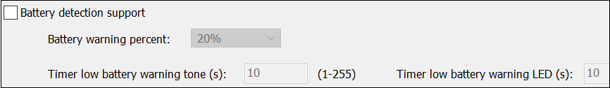
Battery detection support is enabled when the check box is checked.
Reference Battery Voltage (mV): To define the reference voltage for 0% to 90% to show battery remains for the smartphone display, low battery warning and power off. Please get the ten levels according to the battery discharge curve with constant loading and divide into ten levels.
Effective Resistance of Battery (mOhm): The reference battery effective resistance including battery internal resistance, PCB trace and battery wire. It is used to compensate the IR voltage drop due to the additional effective resistance.
Disable charger after charging finish 1 min (Allow low power mode):
Yes: The device will go into power down mode 1min after charger finish (CV mode reach charger finish current), the charger will restart only when adapter out and adapter in again.
No: The device will stop charging after charger finish but will not go into power down mode, under this condition if the battery drops due to loading and reach Re-Charge Voltag, the charger will restart.
Note
Attention:
The adapter 5V behavior in charge box.
If the 5V will not drop even when charger finish, please set 'Disable charger after charging finish 1 min (Allow low power mode)' as 'Yes' so the system could go into power down mode to save the current consumption.
If the 5V will drop after charger finish, the headset will judge it as out of box and power on, connect to smart phone. To avoid this wrong state, please add a 3rd pin as box detect (0= in box) or smart charger box command.
Rapid Charge Support: If Enable, the CC mode charger current will follow the fast charge current setting (defined as 2C) and slow to to (2C/X1, X1 define in item 19) when VBAT reach 4V. e.g, if battery capacity is 50mA, please set 100mA for rapid charge application.
Note
Attention:
If customer modify the charger behavior or use external charger IC, please set rapid charge as disable.
Rapid Charge Current Divisor: Set the parameter 'X1' when enable rapid charge, the charge current will drop to (2C/X1, 2C is fast charge current setting) when battery voltage reach 4V.
High Temp Warning Current Divisor: Set the parameter 'X2' when the thermal ADC reading reach high temperature threshold.
Low Temp Warning Current Divisor: Set the parameter 'X3' when the thermal ADC reading reach low temperature threshold.
Low to High Detection Threshold: Adapter in voltage threshold.
High to Low Detection Threshold: Adapter out voltage threshold.
Low to High Debounce Time (10ms): When adapter in, it will be recognized as adapter in state after voltage level high than the threshod and keep more than this timer.
High to Low Debounce Time (10ms): When adapter out, it will be recognized as adapter out state after voltage level lower than the threshod and keep more than this timer.
Adaptor IO Support: If Yes, 1-wire UART function re-use adapter pin is enabled.
ADP IO Low to High Debounce Time (ms): Adapter IO low to high, and keep high for a certain time, the system will judge as leave 1-wire mode, if '0ms', default debounce time is 10ms.
ADP IO High to Low Debounce Time (ms): Adapter IO high to low, and keep low for a certain time, the system will judge as enter 1-wire mode, if '0ms', default debounce time is 10ms.
Configuration Item and APP Variable Correspondence
Notification Mixing Setting: If the value is enable, the notification will be played in the audio scene, and the two will be mixed; if the value is disabled, the notification will be played in the audio scene, and the notification will be played separately. After the notification is played, the audio will resume playing.
Audio Playback Suppressed Gain (dB): When the Notification mixing setting is enabled, in the audio scene, if a notification comes in, the audio volume will be lowered to highlight the notification effect. You can control how much to suppress the effect by adjusting the suppress gain.
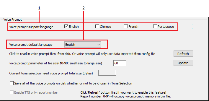
To update the Voice Prompts that the tool identified, follow the instructions below.
Choose the voice prompt supported languages according your needs (Voice prompt support language).
Update the wav file in the folder 'Voice Prompt' files must meet the following requirements:
Mono or Stereo Audio.
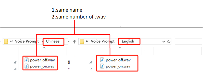
Following sampling rates are allowed: 8KHz, 16KHz, 44.1KHz, 48KHz. File name is written as \*.wav. Be aware that if multiple languages are selected, the wav files in the respective language folder must have the same name. Tool won't recognize files with inconsistent file names in the language folder when multi-language is chosen.
For instance, suppose SoC use both English and Chinese voice prompt. If you want to update power_on.wav and power_off.wav, put them in the folders as shown.
Click the Refresh button to trigger the tool search and obtain the wav files on the hard drive.
Click the Update button to check the required size of the Voice prompt exporting to Bin. Please make ensure the generated Voice Prompt's overall size does not exceed the SoC Flash layout's maximum allowed size.
The wav files will be converted to voice prompt in AAC format. By adjusting the 'voice prompt parameter of file size' parameter, whose valid range is 10-90, you can customize the VP sound quality.
Larger parameter values will result in better VP sound quality, but more flash space will be needed. The voice prompt file name and content will be recorded after the configuration is finished and the rcfg file is exported. The VP information can be used if rcfg is imported the next time.
Which Voice Prompts are exported to Bin is described in this section.
If option Save all of the voice prompts on disk whether or not to be choose in Tone Selection is chosen: All VP files that tool presently recognizes will be imported into Bin.
If option Save all of the voice prompts on disk whether or not to be choose in Tone Selection is not chosen: Only the voice prompt chosen by the tone scenario in 'Tone Selection' is collected by the tool. In other words, it won't be written to Bin if the VP identified by tool is not selected in 'Tone Selection'.
If Enable TTS only report number is checked, some VPs will automatically be exported to Bin for TTS function (tool recognizes the VP names as '0', '1', '2', '3', '4', '5', '6', '7', '8', '9').
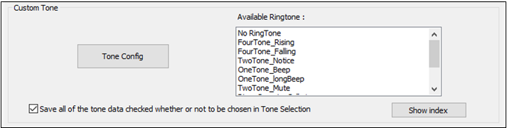
'Available Ringtones' lists the ringtones that can be chosen for export to bin file. Click the Tone Config button to modify the 'Available Ringtone'. Tool offers 45 non-editable Ringtones. Ringtone customization is also supported.
When a ringtone is selected, it will appear in the list of 'Available Ringtones'.
Click the Play button to hear the Ringtone effect.
Click the Value button to examine Ringtone data.
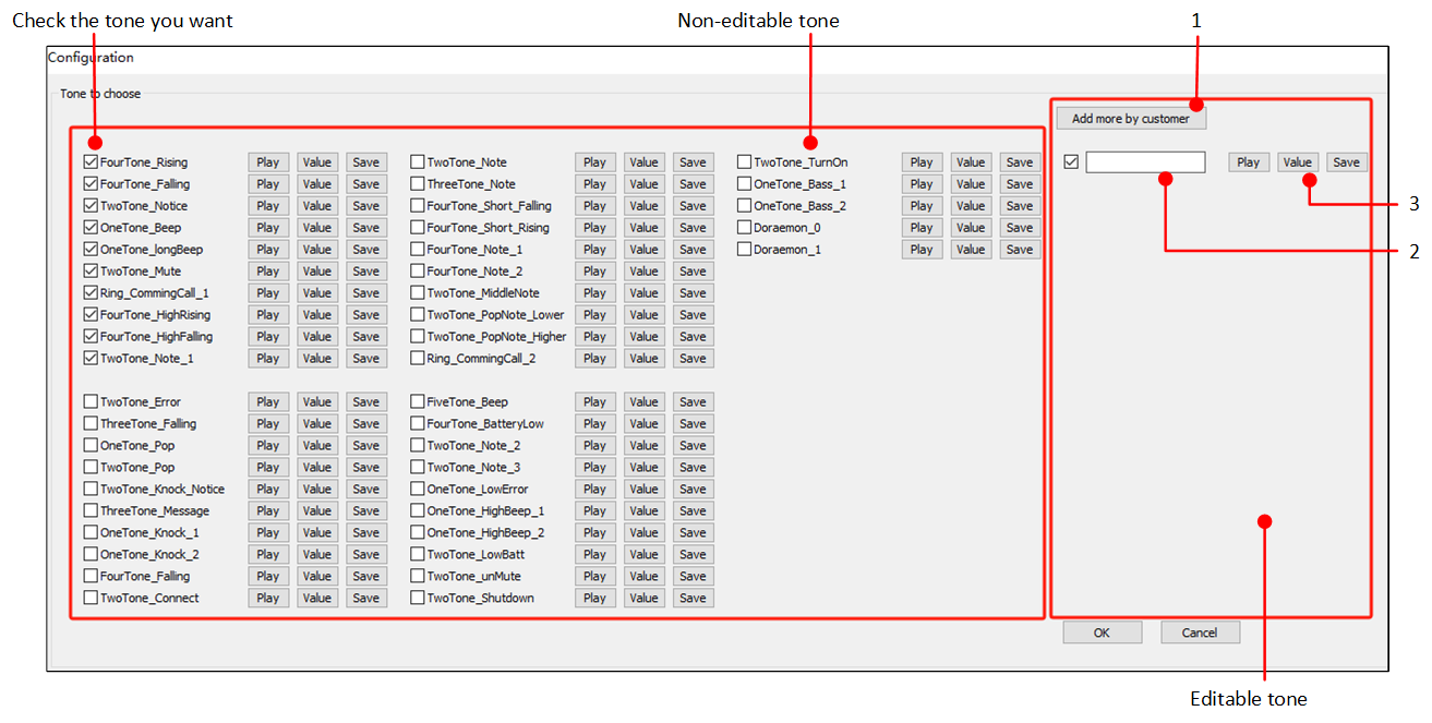
Add a customized ringtone:
Click button Add more by customer to add a new ringtone.
Give the custome ringtone a name in the editbox. Make sure this name is different from the existing 'non-editable Ringtone' name.
Click the Value button to fill in the tone data, then save it. Click the Play button to hear the Ringtone effect.
Note
Attention:
Select the checkbox to display this custom Ringtone in 'Available Ringtones' list.
This section describes which ringtones are exported to Bin.
If the option Save all of the tone data checked whether or not to be chosen in Tone Selection is chosen:
All ringtones in 'Available Ringtone' will be exported to Bin.
If the option Save all of the tone data checked whether or not to be chosen in Tone Selection is not chosen:
The tool only collects the ringtones selected by the tone scenario in 'Tone Selection'. In other words, if the ringtone in 'Available Ringtone' is not chosen in 'Tone Selection', it will not be written to Bin.
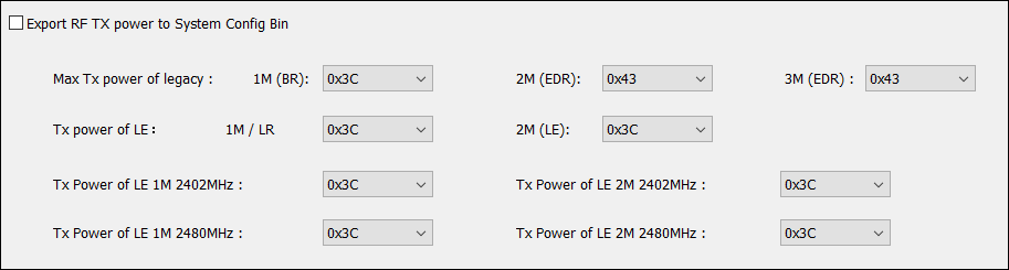
These RF parameters will be exported to the new generated System configuration Bin only if Export RF TX power to System Config Bin is enabled. Otherwise, it will not export to bin file.
Max TX Power of Legacy: Legacy BDR/EDR TX power setting.
TX Power of LE: LE TX power setting.
TX Power of LE 1M/2M 2402MHz/2480MHz: individually fine tune 2402Hz (CH0) and 2480MHz (CH39) TX power setting for certification purpose, this is specially for band edge test item requirement.
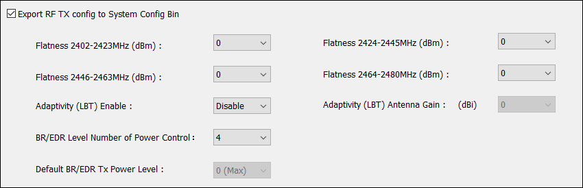
These RF parameters will be exported to the new generated System configuration Bin only if Export RF TX config to System Config Bin is enabled. Otherwise, it will not export to bin file.
Flatness 2402-2423MHz/2424-2445MHz/2446-2463MHz/2464-2480MHz (dBm): The RF channels are divided into low/mid1/mid2/high groups through the 79 channels, due to the PCB thickness, impedance control and component variance, the RF TX performance may be varied among different groups, this parameter is use to do compensation in the four groups to keep better flatness for the bluetooth channels.
Adaptivity (LBT) Enable: Enable Adaptivity for CE Directive.
Adaptivity (LBT) Antenna Gain: Fill in the antenna peak gain for adaptivity parameter.
BR/EDR Level Number of Power Control: define the TX power control level 3(0,1,2) or 4 (0,1,2,3), 0 is the max level defined in RF TX configuration above. The default TX power level is 0 and could be configuration by Default BR/EDR TX power Level.
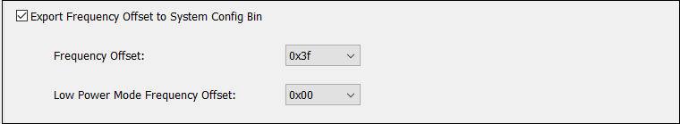
These RF parameters will be exported to the new generated System configuration Bin only if Export Frequency Offset to System Config Bin is enabled. Otherwise, it will not export to bin file.
Frequency Offset: Tune the IC internal compensation capacitor value (XI/XO), the tunable range is 0x00~0x7f, with 0.3pF change per step. The default 0x3F.
Low Power Mode Frequency Offset: Tune the IC internal compensation capacitor value (XI/XO) in DLPS mode, this wrong parameter will cause disconnect issue.
The system configuration bin file contains the configuration for the System Configuration, Charger, and RF TX tabs. However, some of the fields on the Charger tab are kept in the APP parameter configuration bin.
Configuration in the Audio Route tab have an impact on the framework block. These setting is stored in the APP parameter configuration bin file.
RingTone/Voice Prompt and LED information are stored in separate blocks in the APP parameter configuration bin file. In some IC part number, RingTone/VP may be saved in a separate VP bin file.