MPPG Tool
Realtek MPPG Tool supports flash programming for RTL87XXX series chips.
First, you may refer to Appendix about EVB connection and pre-settings. There are two modes of downloading image to chip. One is 'MP Mode', which is for factory mass production; while the other is 'RD Mode', which is for factory R&D to do some debugs about their image downloading to chip.
In 'MP Mode', tool only accept packed image file which will be packed through 'Pack Tool'. In this mode, it provides two methods to modify Bluetooth address per chip; provides selection to merge RF parameters and Bluetooth address etc. in previous stage (e.g. MP Test); provides selection to modify frequency offset; supports auto-detect serial ports connected.
In 'RD Mode', tool can only accept downloading individual sub-images, also it provides method to modify several configuration parameters. In this mode, detecting and manipulating one or more serial ports is also supported.
MP Tool Introduction
Guide Interface
Guide Interface
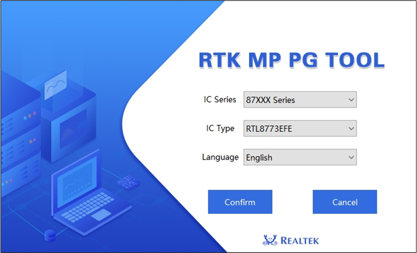
Before enter main interface, please select proper IC Series, IC Type and Language (Guide Interface).
Click IC Series to select IC series you are going to use.
Then click IC Type to select IC type you are going to use. Please make sure correct IC type is selected, or unexpected situation maybe happen in PG procedure.
Currently two languages are supported: 'English' and 'Chinese simplified'.
After IC type and language selection, click Confirm to enter main interface of MPPG Tool.
If Cancel is clicked, the application terminated and exit.
Main Interface
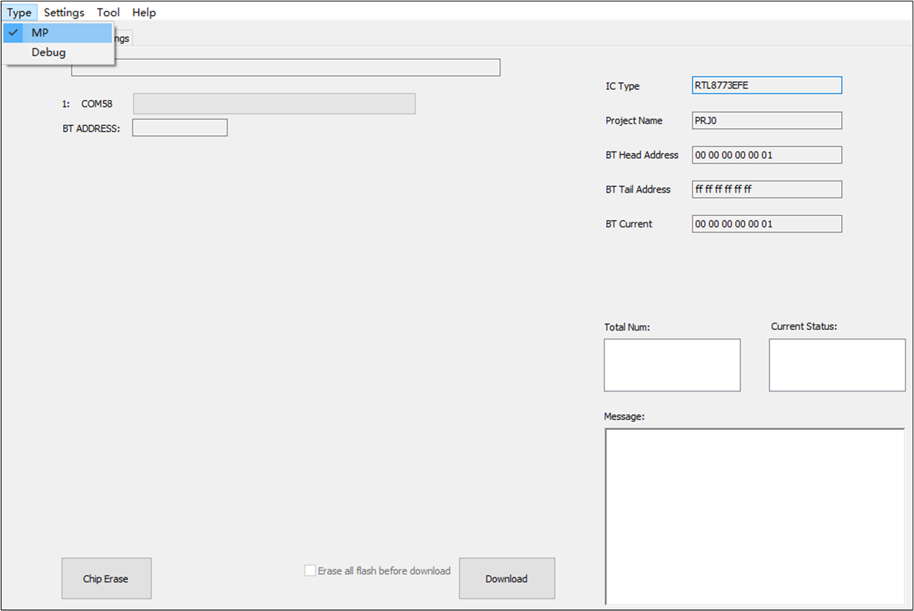
Main Interface and Switch Mode shows the main interface of MPPG Tool.
You can switch 'MP mode' or 'RD Debug mode' via click Menu Type.
Main Interface and Switch Mode
MP Mode
In 'MP Mode', MPPG Tool supports functions as follows:
Chip Erase
Download with Chip Erase
Parallel Downloading up to Eight Ports at a Time
Bluetooth Address Management
Read Back & Merge
Frequency Offset
Save & Cancel Settings
Two Kinds of Bluetooth Address Setting Method
Some Other Settings
We will elaborate on these functions in the following chapters.
MP Setting
Before flash programming, you could modify some settings in Tab MP_Settings.
Lock & Unlock
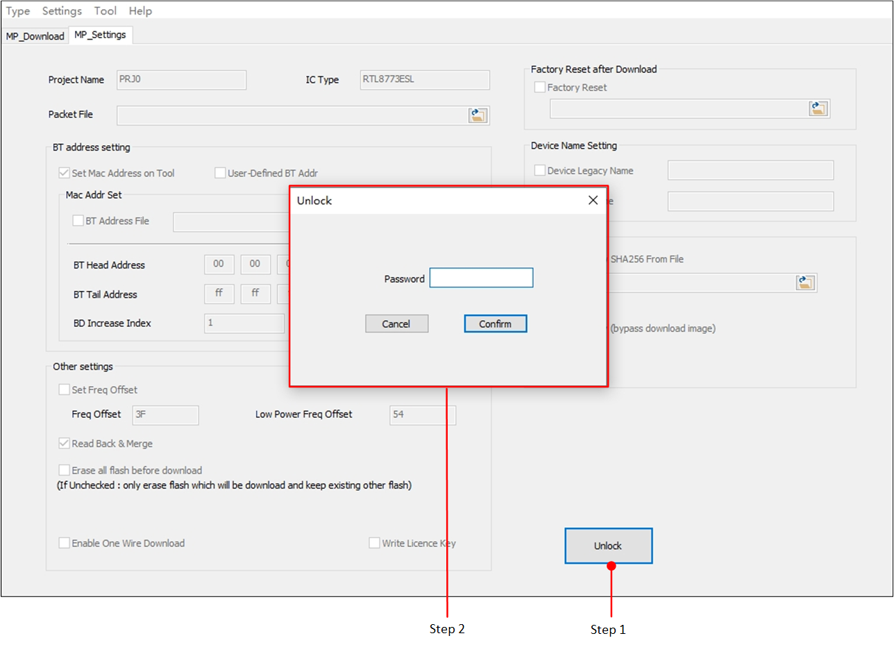
Once entered, this tab is always locked to prevent misoperation.
Click Unlock, enter password in pop-up dialog and click Confirm, then you can set configuration items in this tab (Unlock MP Settings). Usually the initial password is '1'.
Unlock MP Settings
You can also modify password of Tab MP_Settings via menu by (Modify Password).
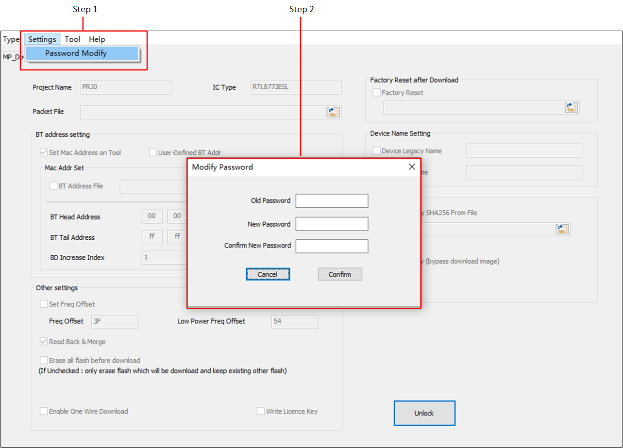
Modify Password
In 'Modify Password' dialog, enter old password, new password, and reenter new password.
Password can be any characters, but empty password is not allowed.
After setting configurations in Tab MP_Settings, you can choose to save the modification or discard them.
If you don't want to save them, click Reset to previous to discard modification, and parameters in this tab will be reversed to previous setting, then click Lock to lock the tab (Cancel Settings).
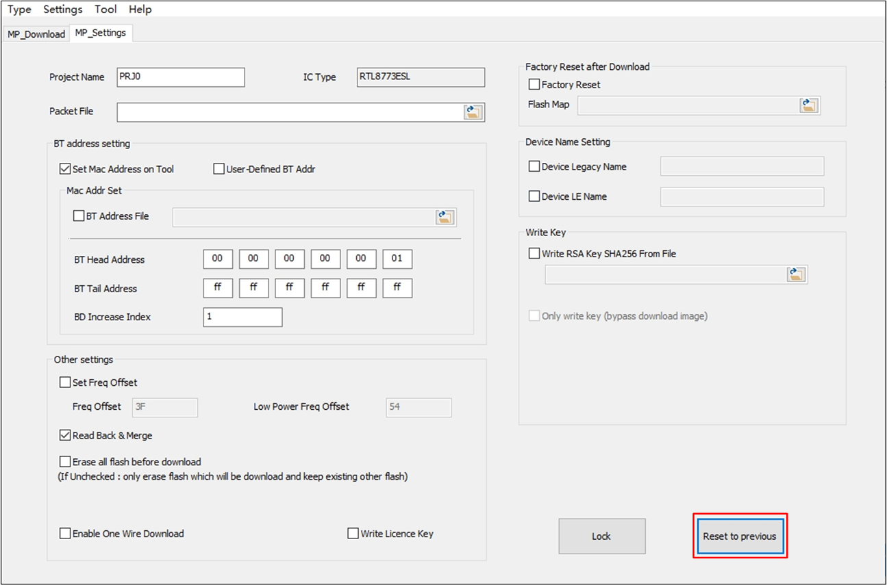
Cancel Settings
If you want to save the configurations, just click Lock to save setting modification and lock the tab.
Configuration Item
In Tab MP_Settings you can modify the following settings:
Project Name
Packet File
Bluetooth Address Setting
Frequency Offset
Read Back & Merge
Device Name Setting (particular function for specific chips)
Write Key (particular function for specific chips)
Enable One Wire Download (particular function for specific chips)
Factory Reset (particular function for specific chips)
-
Project Name
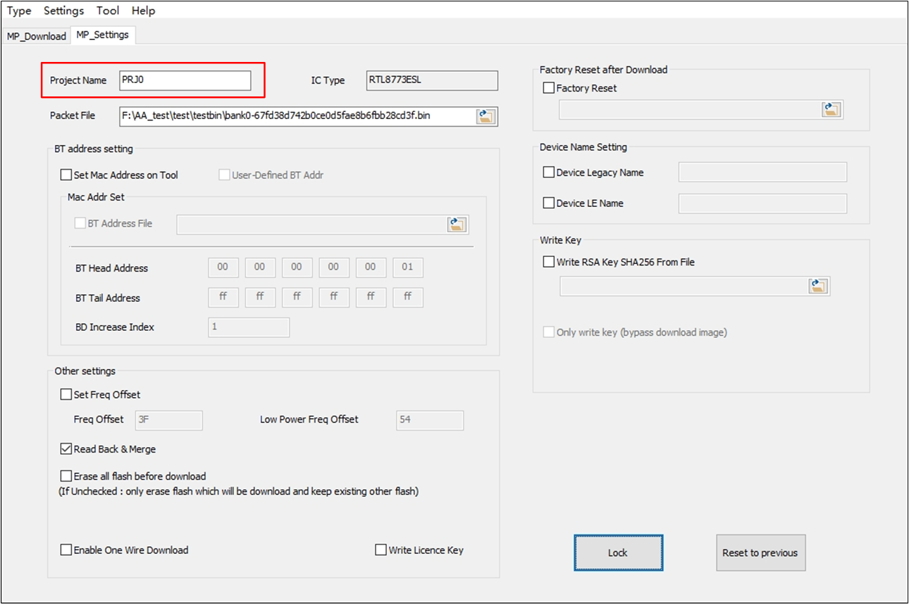
Modify Project Name
You can enter a new project name to distinguish from other PG projects, as shown in Modify Project Name.
-
Packet File
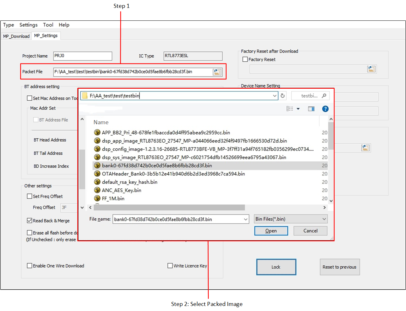
Import Packet File
There are two ways to select packet file:
Click the open folder icon firstly, an 'Open' dialog will pop up. Then select the packet file corresponding to current IC type (Import Packet File).
Or you can type in the pack file name directly in the Packet File editbox.
-
Bluetooth Address Setting
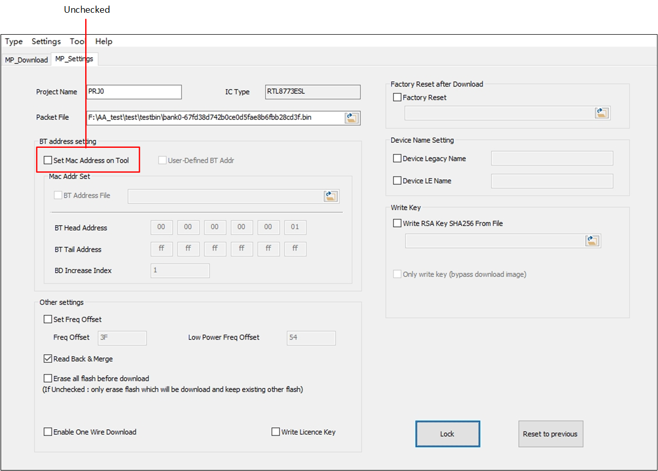
Uncheck 'Set Mac Address on Tool'
-
If there is no need to configure Bluetooth address per chip in MP download, uncheck Set Mac Address on Tool (Uncheck 'Set Mac Address on Tool').
Attention
If you want to keep Bluetooth address configured in previous stage (e.g. MP Tests), just uncheck Set Mac Address on Tool, and make sure Read Back & Merge is checked.
-
If you want to program Bluetooth address down to chip in this stage, just check Set Mac Address on Tool. There are two ways to configure Bluetooth address setting.
Tool Manage Bluetooth Address and Use Tool Set Parameter
-
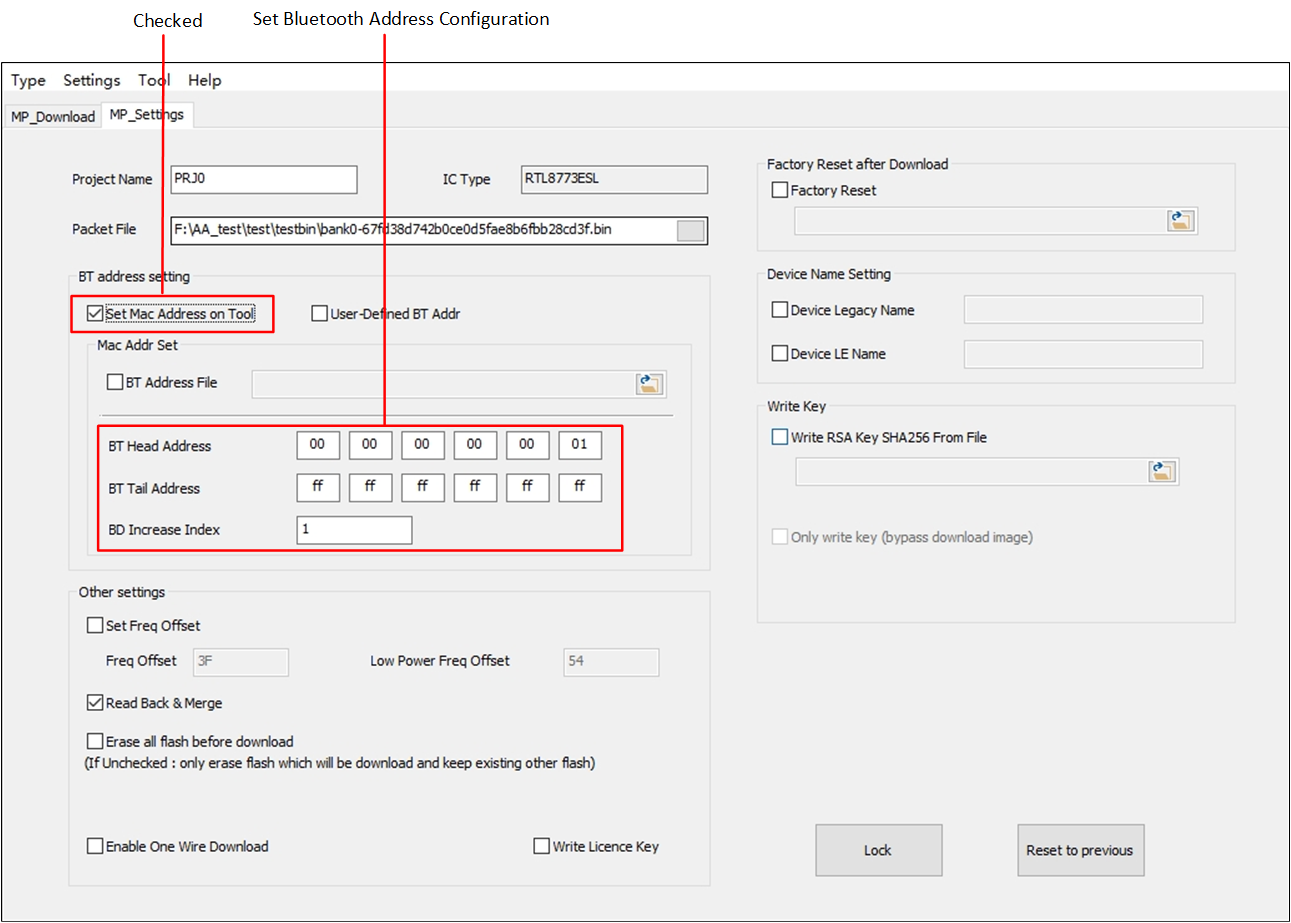
Configure by filling addresses on UI, please do the following steps (Tool Manage Bluetooth Address and Use Tool Set Parameter):
Check the Set Mac Address on Tool.
Configure BT Head Address and BT Tail Address, the Bluetooth tail address should be greater than Bluetooth head address.
Set BT Increase Index, the Bluetooth increase index should be in the range from 1 to 99.
If you choose this way, in the following MP Download procedure, Bluetooth address per chip will be manipulated from Bluetooth head address to Bluetooth tail address, by the step of Bluetooth increase index.
-
Configure by providing an imported source file, just check Set Mac Address on Tool and BT Address File, then select Bluetooth address source file.
If you choose this way, in the following MP Download procedure, Bluetooth address per chip will be got from Bluetooth imported source file you selected, as shown in Tool Manage Bluetooth Address and Use Imported Txt File.
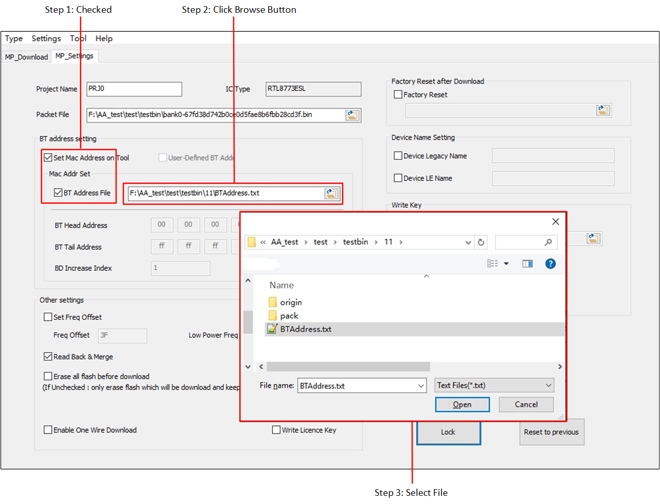
Tool Manage Bluetooth Address and Use Imported Txt File
The Bluetooth address source file should be formatted like this:
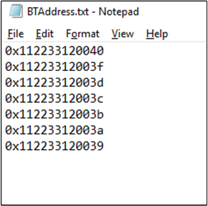
Imported Bluetooth Address File Format
-
-
Fail Address Reuse
Some ports' download procedure may fail due to some unexpected errors. The tool will save 'fail address' in
BTAddress.txtinMPPGTool.exe's folder during PG procedure, and reuse 'fail address' got fromBTAddress.txtfirstly in the next PG procedure. After the 'fail address' got fromBTAddress.txtis used up, the next Bluetooth address acquisition depends on which way you choose to configure Bluetooth address setting in previous item 2. Bluetooth address manage flow under this scenario is shown below in Bluetooth Address Manage Flow.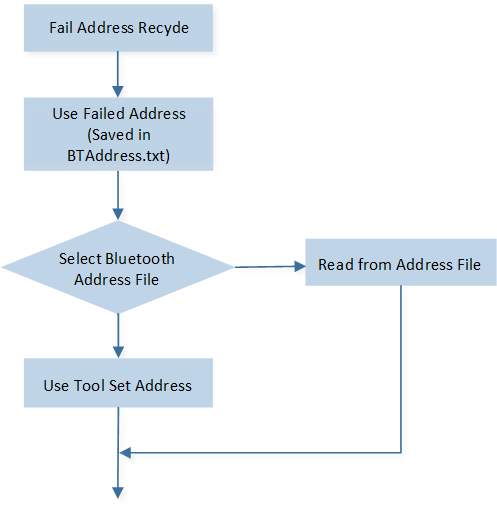
Bluetooth Address Manage Flow
-
-
Frequency Offset
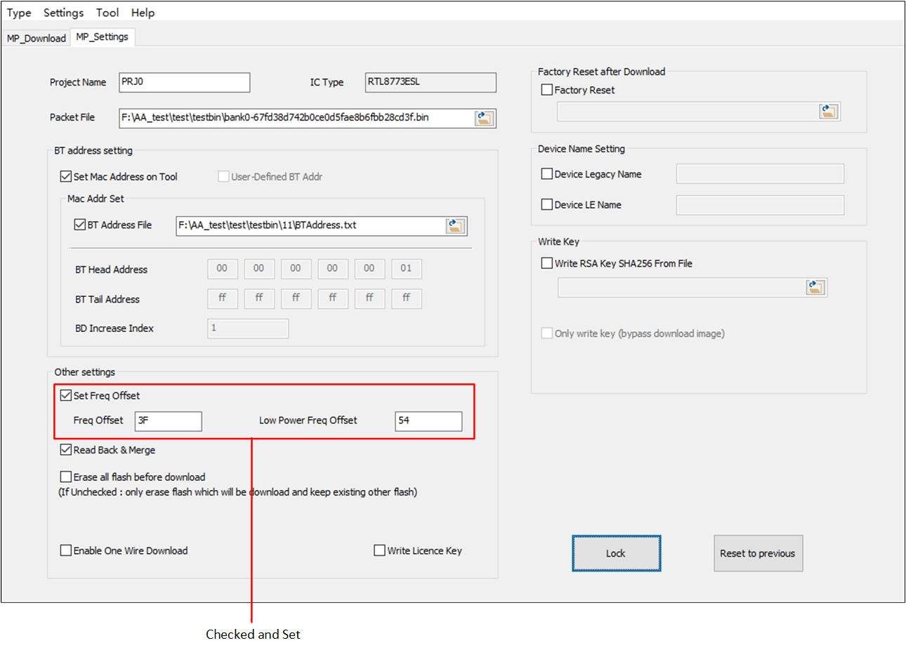
Set Frequency Offset
If you want to set frequency offset, please check the Set Freq Offset and input hexadecimal value (range from 0x0 to 0x7F). Out of range input will be limited to maximum or minimum available value (Set Frequency Offset).
If there is no need to set frequency offset in MP Download procedure, just uncheck Set Freq Offset.
-
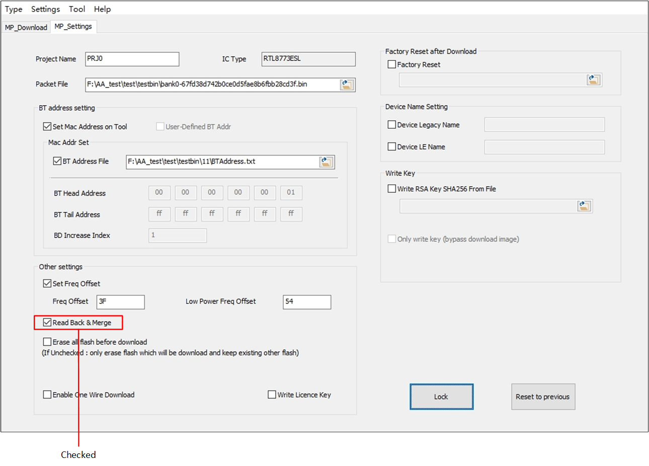
Read Back & Merge
If you need to keep parameters (e.g. 'Bluetooth Address', 'Freq Offset') configured in previous stage (e.g. MP Tests), check the Read Back & Merge, as shown in Read Back and Merge.
Read Back and Merge
Attention
Assume that Read Back & Merge is checked. In Tab MP_Download, you may use Chip Erase button or set Erase all flash before download checked, it will cause different consequences as below:
Click Chip Erase firstly and then click Download, Read Back & Merge procedure will not actually take effect, because parameters set in previous stage will be erased firstly.
Set Erase all flash before download checked and click Download, Read Back & Merge will take effect.
More detailed instructions will be described in MP Download.
-
Device Name Setting
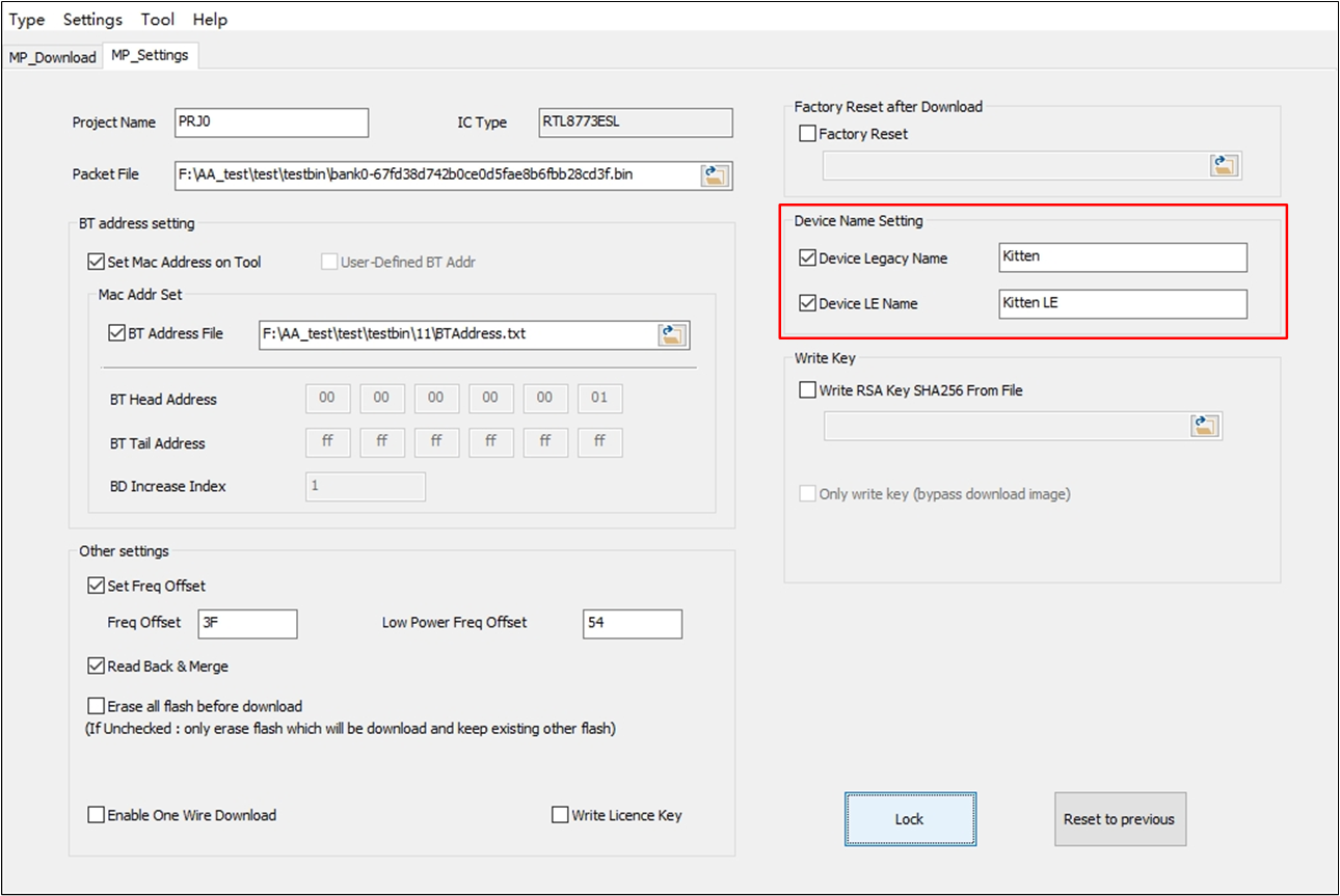
Device Name Setting
The Device Legacy Name and Device LE Name could be configured in this block, you can only set one, or all of them.
If you want to configure them, check the checkbox and fill in the name (Device Name Setting), otherwise just set unchecked.
-
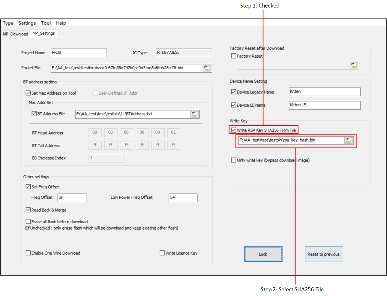
Write Key
For some secure chips which need to write RSA Key SHA256 into efuse, the tool provides function of writing RSA Key SHA256 into efuse by importing a valid SHA bin file (Writing RSA Key SHA256).
Writing RSA Key SHA256
Attention
The SHA bin file must be corresponding to the private RSA key which used to re-sign sub-images.
If one chip is already written RSA Key SHA256 into efuse, don't write different RSA Key SHA256 info into efuse, otherwise the SHA256 field in efuse will be disordered and the chip will never run successfully.
RTL87X3E chips must use VBAT (battery) power in key write procedure.
If Write RSA Key SHA256 is checked and import a SHA bin file, in the MP download procedure tool will check SHA information first. SHA information check flow is as follows:
-
Check SHA Information from Imported Bin File
If imported SHA bin file is opened failed or checked invalid, tool will pop up an error message box (SHA Bin File Open Failed & SHA Bin File Invalid).
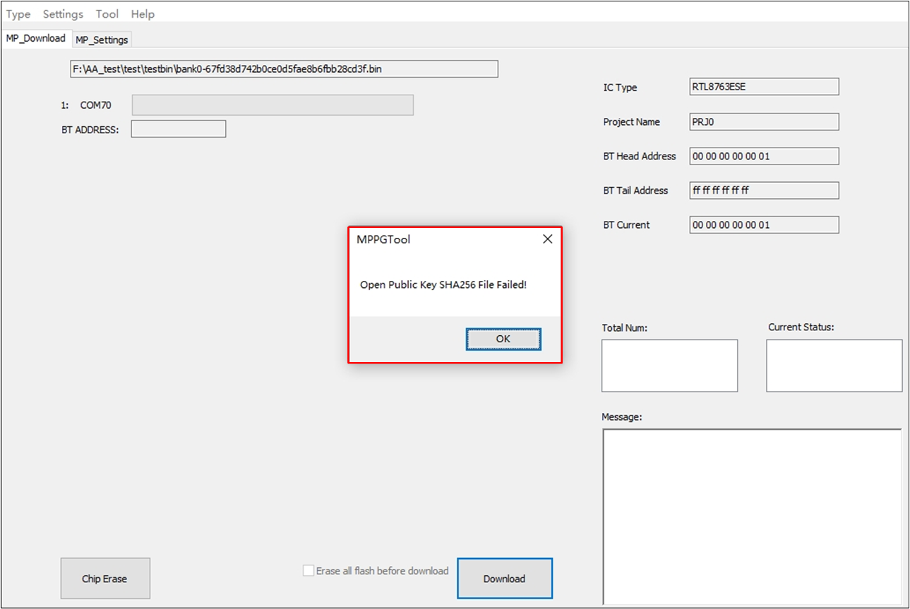
SHA Bin File Open Failed
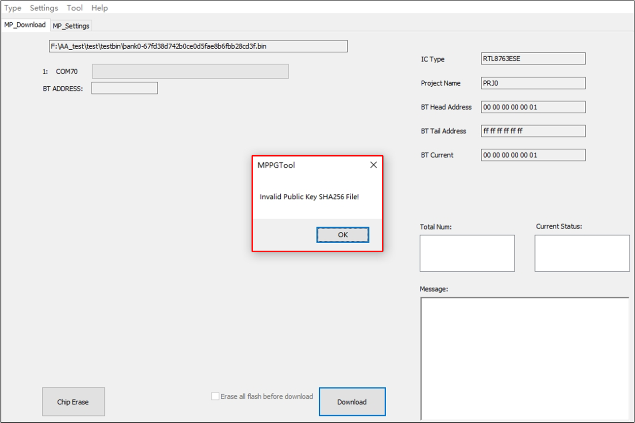
SHA Bin File Invalid
-
Check Secure Chip Enabled
If imported SHA bin file is valid, tool will check whether the chip is secure boot enabled.
If the chip is secure boot disabled, indicate that the chip not allowed to write SHA information into efuse. Tool will print an error message (Forbid to Write SHA Info).
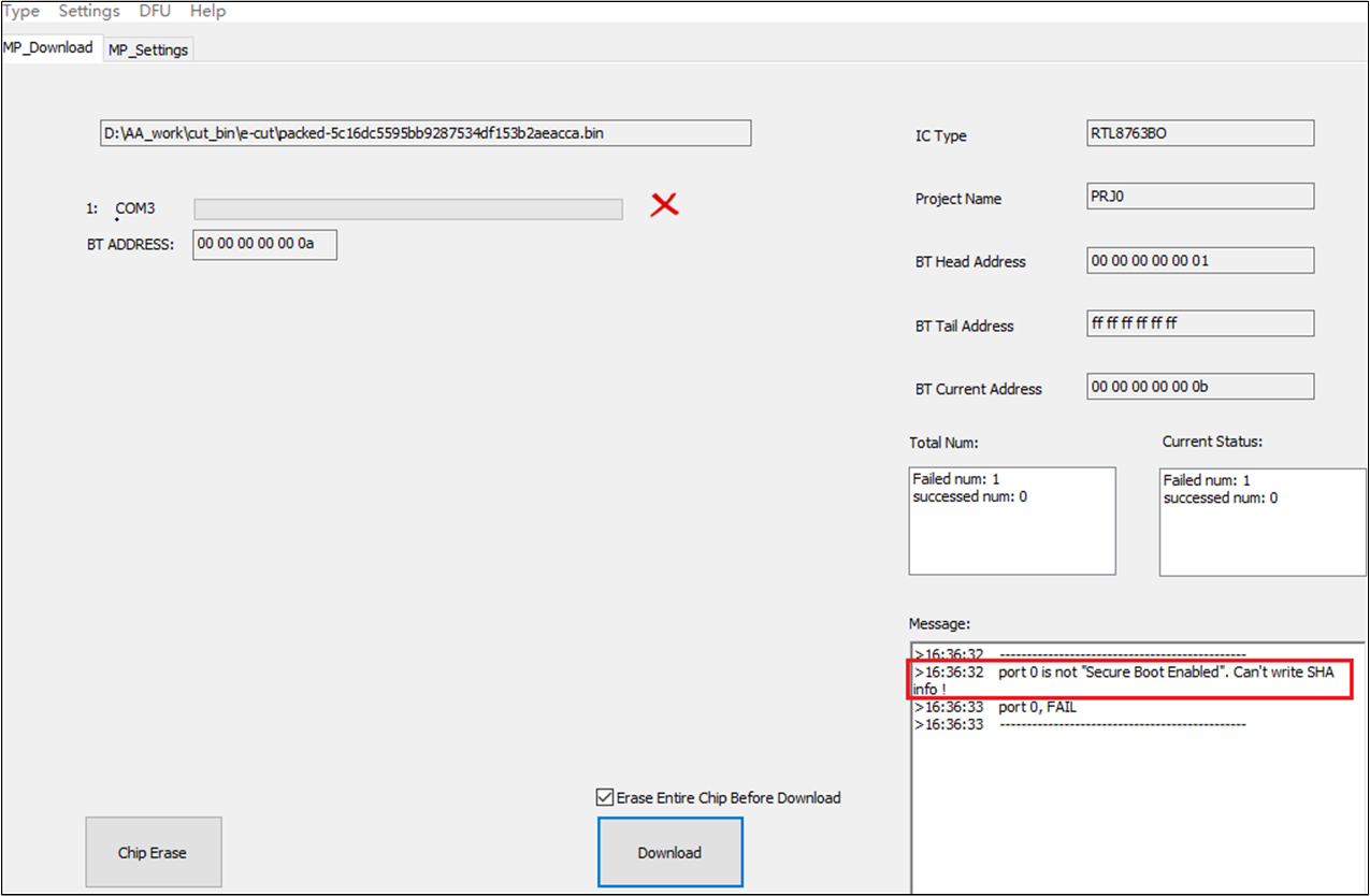
Forbid to Write SHA Info
-
Check SHA Information between Read Back SHA and Imported Bin File
If imported SHA bin file is valid and chip is secure boot enabled, tool will read back SHA information from efuse and check them with the imported SHA bin file.
-
If SHA information read back from efuse is invalid or conflict with the imported SHA bin file, tool will pop up an error message box (Conflict SHA Info).
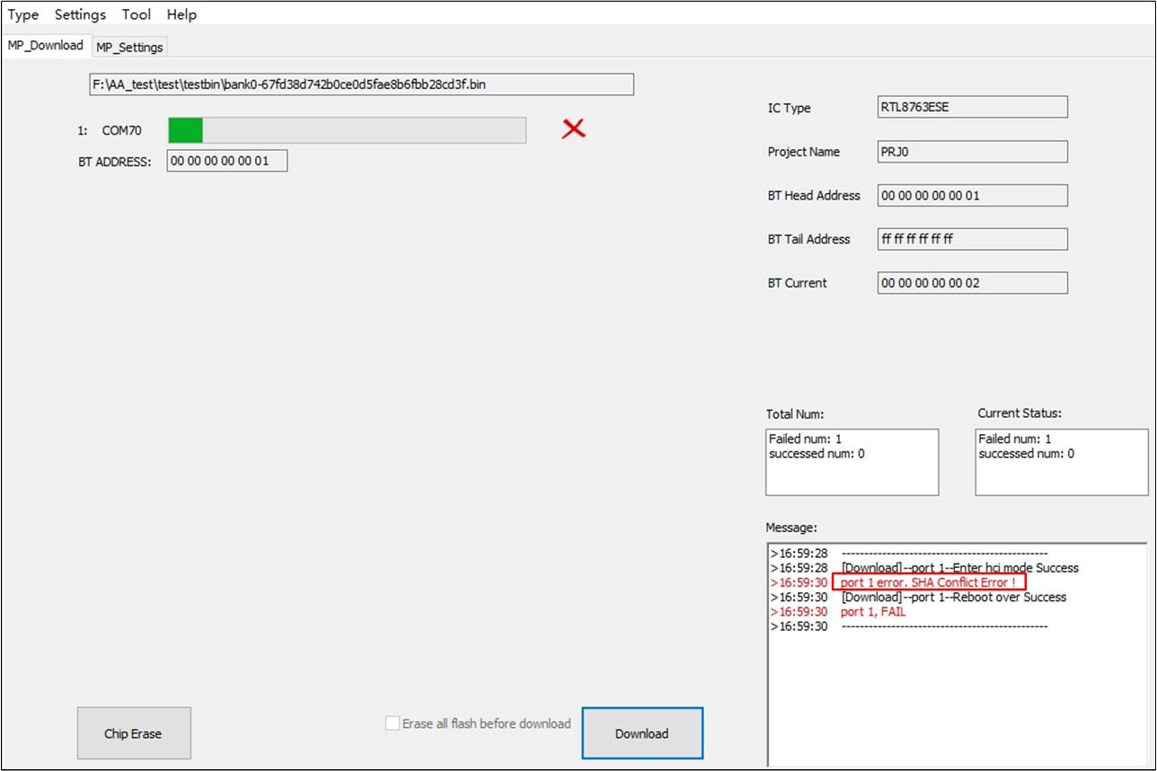
Conflict SHA Info
If SHA information read back from efuse is valid and is the same with the imported SHA bin file, tool just enter into PG procedure and skip writing SHA into efuse because the chip is already written the same SHA information.
If SHA information read back from efuse is empty, indicate that the chip is never written SHA information into efuse before, so tool will enter into formal PG procedure with SHA writing.
-
Additionally, only write SHA256 bin and bypass download pack bin are supported.
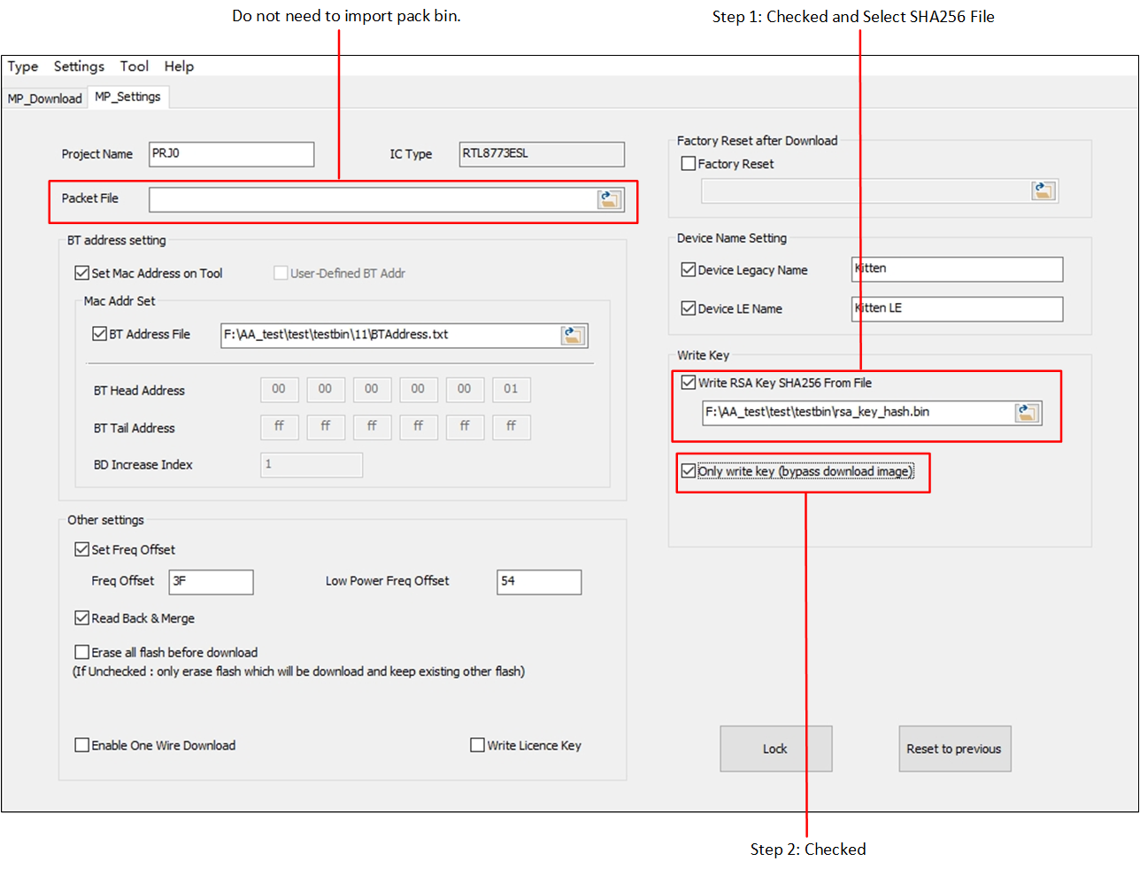
Only Write RSA Key SHA256
-
Enable One Wire Download
Some IC types of the RTL87X3E and RTL8773D series support the one wire download feature.
Attention
Can't erase and write boot patch image if Enable One Wire Download is checked.
Chip Erase is not allowed to click in Tab MP_Download if Enable One Wire Download checked in Tab MP_Settings.
MPPG Tool will send app reset command by clicking Download in one wire download mode, which will trigger SoC to reset to access the one wire download program. If the app on the SoC cannot run normally, and it is not in the state of automatic reset constantly, it is necessary to rely on other ways to make the IC reset to access the one wire download program after clicking Download. After clicking Download, wait for the SoC to reset to access the one wire download mode, the timeout is set to 20s.
Recommended to have two bank images burned before switching to one wire download mode.
The supported baud rates of the chip is dependent on the capacitance. Please choose the chip's supported baud rate.
One wire download flow is as follows:
-
In Tab MP_Settings, check Enable One Wire Download (Check 'Enable One Wire Download' in Tab 'MP_Settings') and configure other required settings.
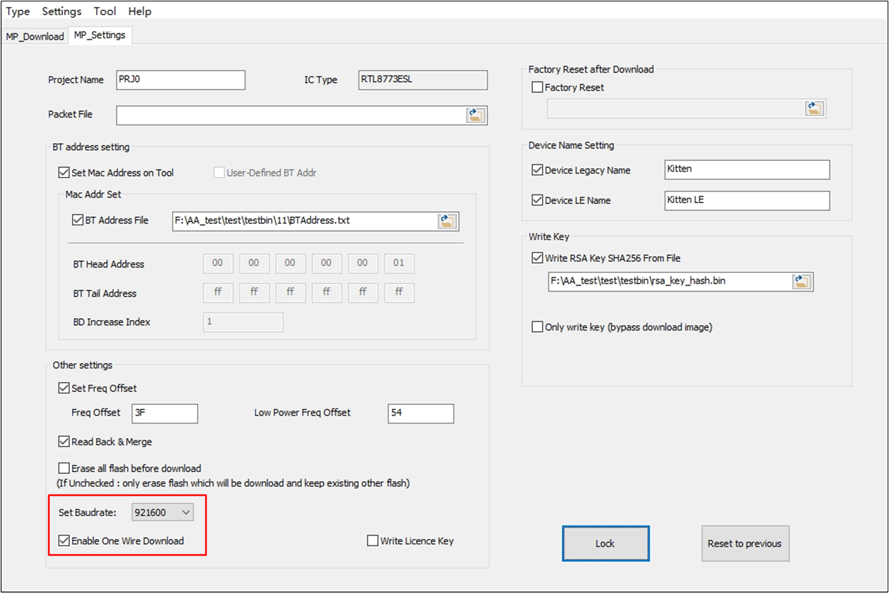
Check 'Enable One Wire Download' in Tab 'MP_Settings'
After checking Enable One Wire Download checkbox, an option to select the baud rate will be displayed. Set the appropriate baud rate.
-
Click Download in Tab MP_Download (Click 'Download' Button in Tab 'MP_Download').
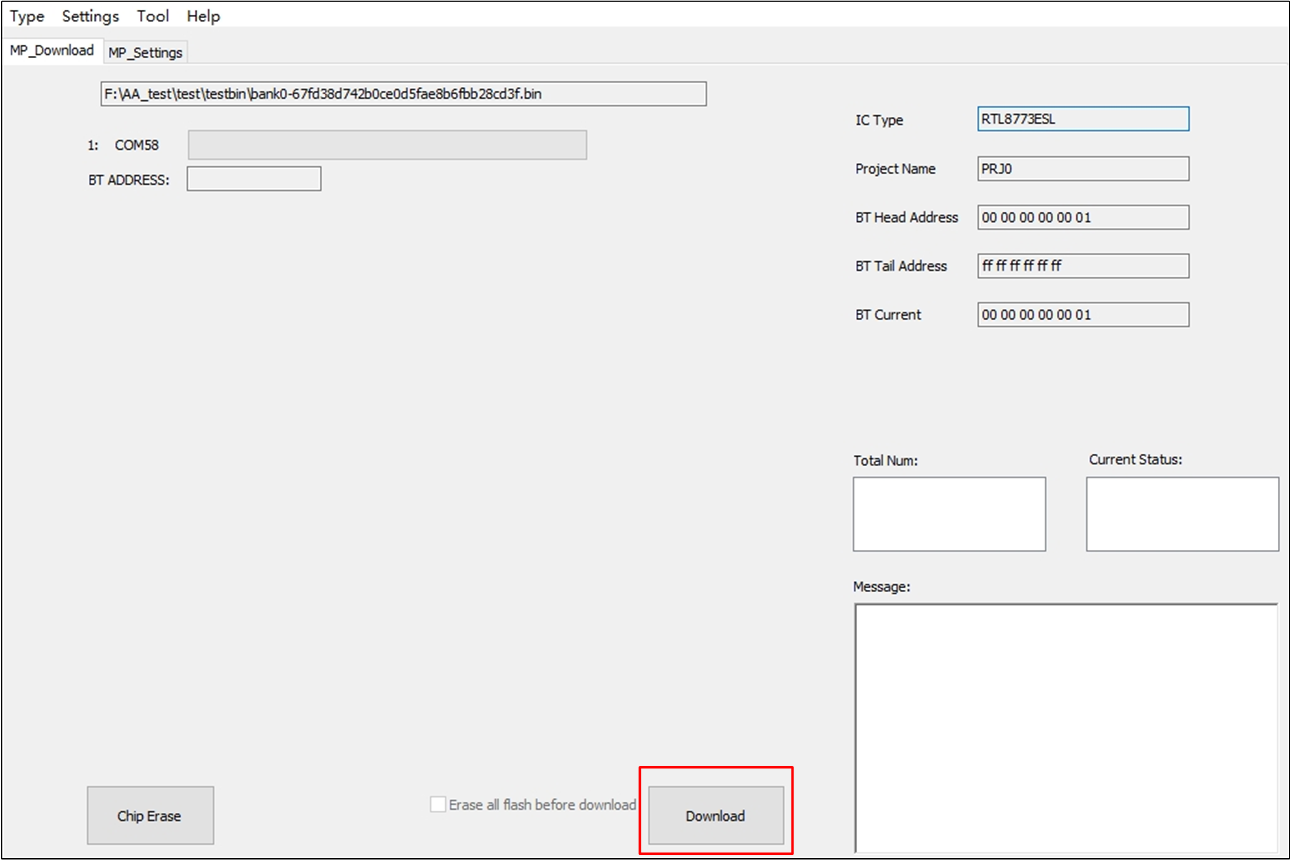
Click 'Download' Button in Tab 'MP_Download'
-
Factory Reset
If you want to do factory reset procedure after the download is completed, check the Factory Reset checkbox and import
flash map.ini, otherwise do not check the box.
MP Download
As shown in MP Download Interface, this is the 'MP Download' interface.
Before download, make sure proper packet image file is selected in Tab MP_Settings, or a pop-up message box will telling you 'Pack bin does not exists' or other error messages.
MP Download Interface
Assume that you've already set some parameters (e.g. 'Bluetooth Address', 'Freq Offset') in previous stage, and you want to read back previous setting, please set Read Back & Merge checked in Tab MP_Settings.
Under assumption above, if you also want to erase the entire chip, there are two kinds of download procedure, which have different results:
-
Click Chip Erase firstly, then click Download (Chip Erase Button and Download):
Click Chip Erase will trigger entire chip erase, so all parameters set in previous stage (ex. parameter set in MP Tests) will be cleared;
Click Download to download image to chip, Read Back & Merge will not take effect because parameters set in previous stage were already cleared.
-
Download with Erase all flash before download checkbox checked ('Erase all flash before download' Checked and Download):
Read back previous set parameters from flash;
Erase entire chip;
Merge flash read back parameters with packet file, then download to chips, Read Back & Merge will take effect.
If you do not need Read Back & Merge and uncheck it, the above two procedures will get the same result.
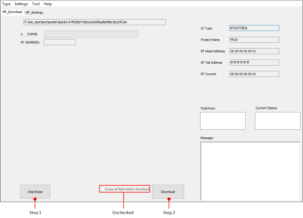
Chip Erase Button and Download
Erase all flash before download checkbox is checked in Tab MP_Settings.
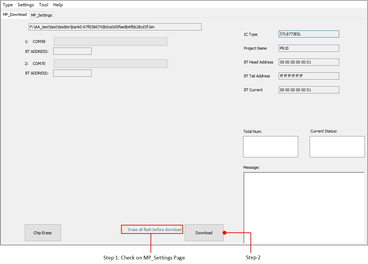
'Erase all flash before download' Checked and Download
If you check Set Mac Address on Tool, it will manipulate Bluetooth address by tool itself.
Here are two scenarios:
-
Use Bluetooth head address, Bluetooth tail address with Bluetooth increase index.
As shown in Bluetooth Address Usage Logic, on the information area, BT Head Address, BT Tail Address will show the Bluetooth address you set in Tab MP_Settings, and BT Current will show the next Bluetooth address which is going to program down to chip.
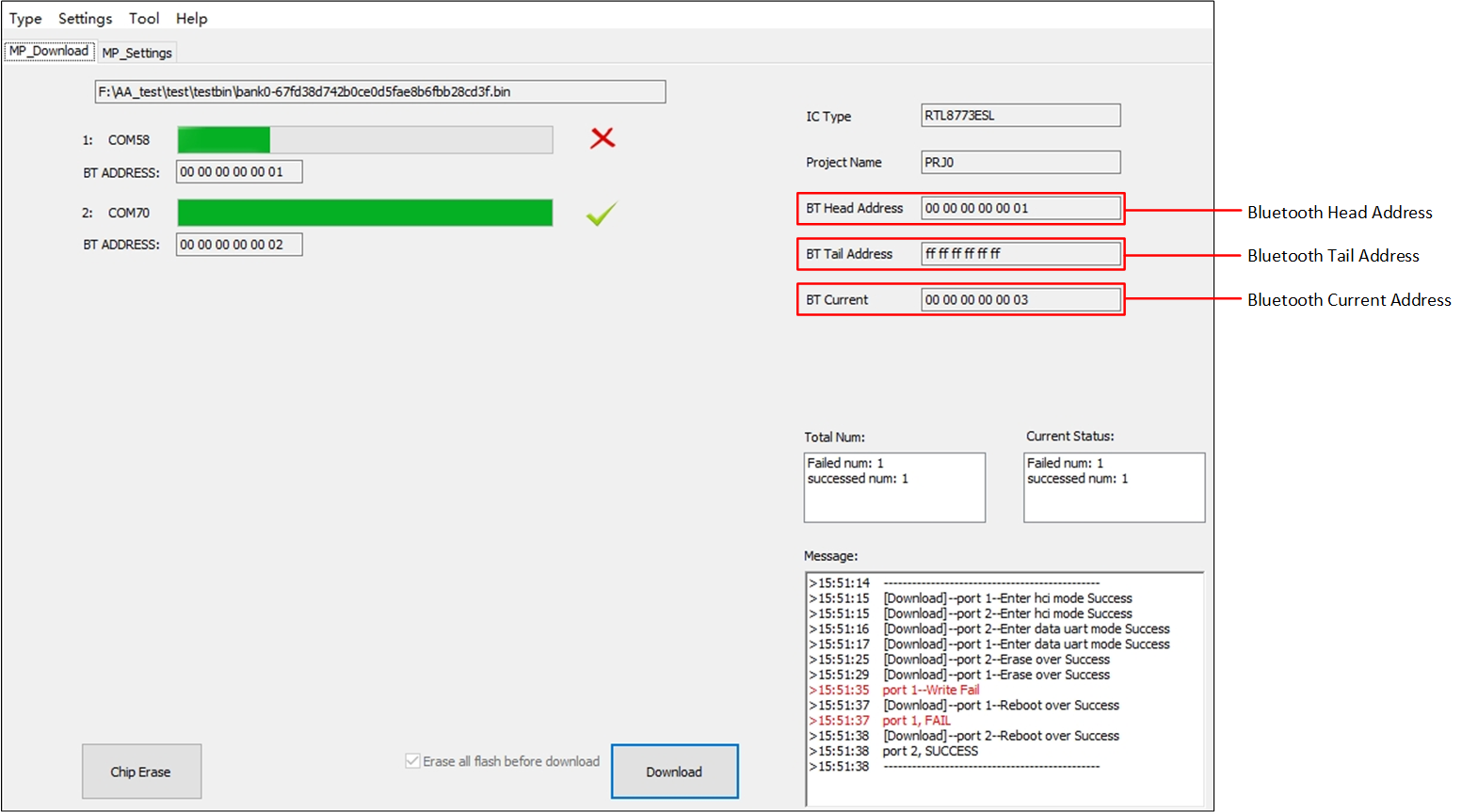
Bluetooth Address Usage Logic
Attention
During 'MP Download' procedure, Bluetooth current address grow by Bluetooth increase index regardless of downloading fail.
After 'MP Download' procedure, Tool will save failed address. Then during the next PG procedure, it will reuse failed address. Until all failed addresses are used up, Bluetooth current address will automatically grow by Bluetooth increase index set in Tab MP_Settings.
Failed addresses will be saved in
BTAddress.txtinMPPGTool.exe's folder as shown in Bluetooth Address File Format.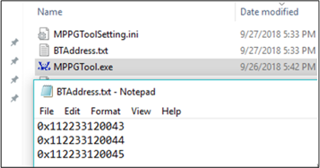
Bluetooth Address File Format
-
Use 'Bluetooth Address File' to set Bluetooth address.
Bluetooth address will automatically be loaded from Bluetooth address file, and the information area will not work in this scenario, as shown in Use Bluetooth Address File below.
After PG procedure, the fail addresses and unused addresses will be saved in the same Bluetooth address file you imported and at the same time the used addresses will be deleted.
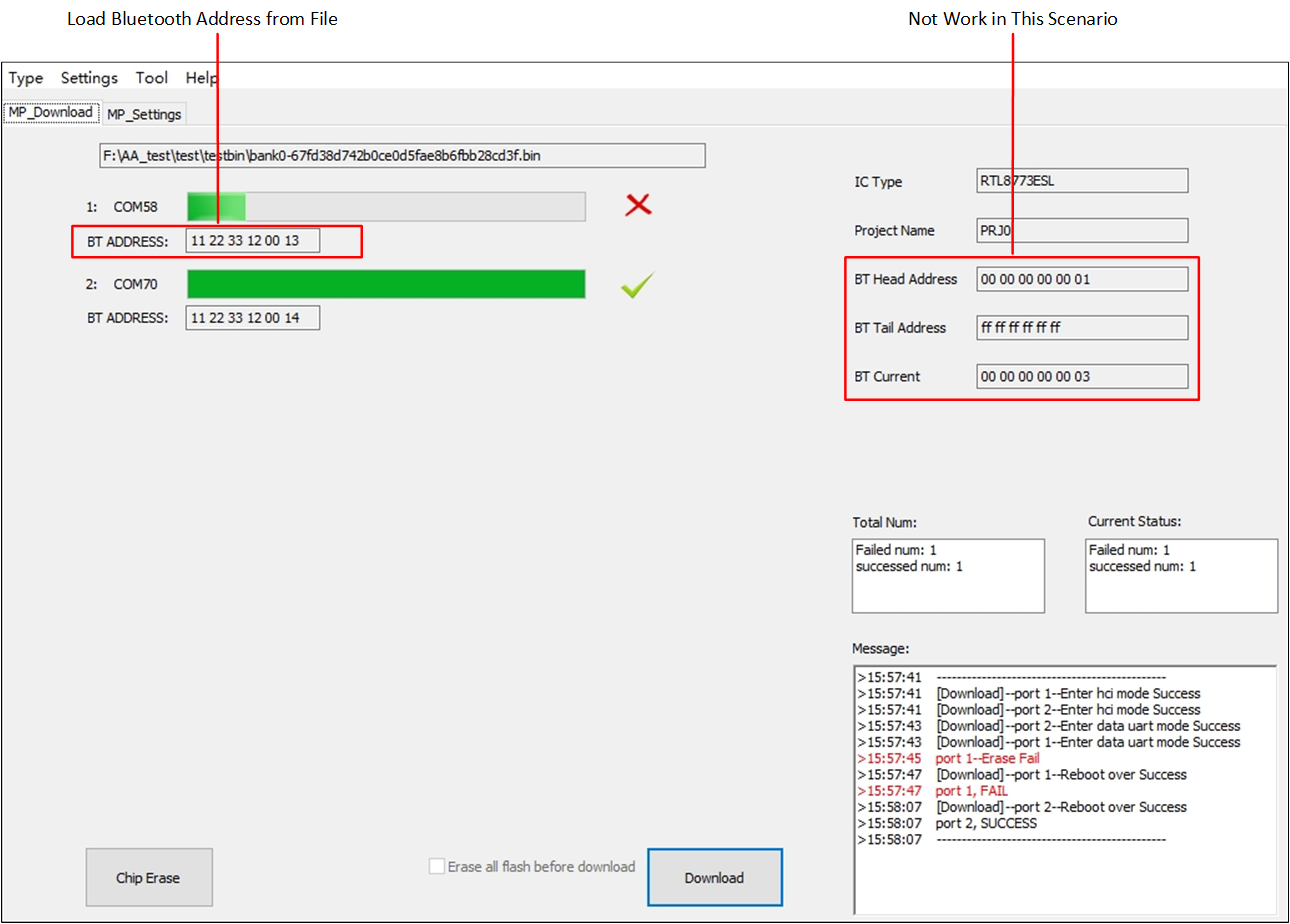
Use Bluetooth Address File
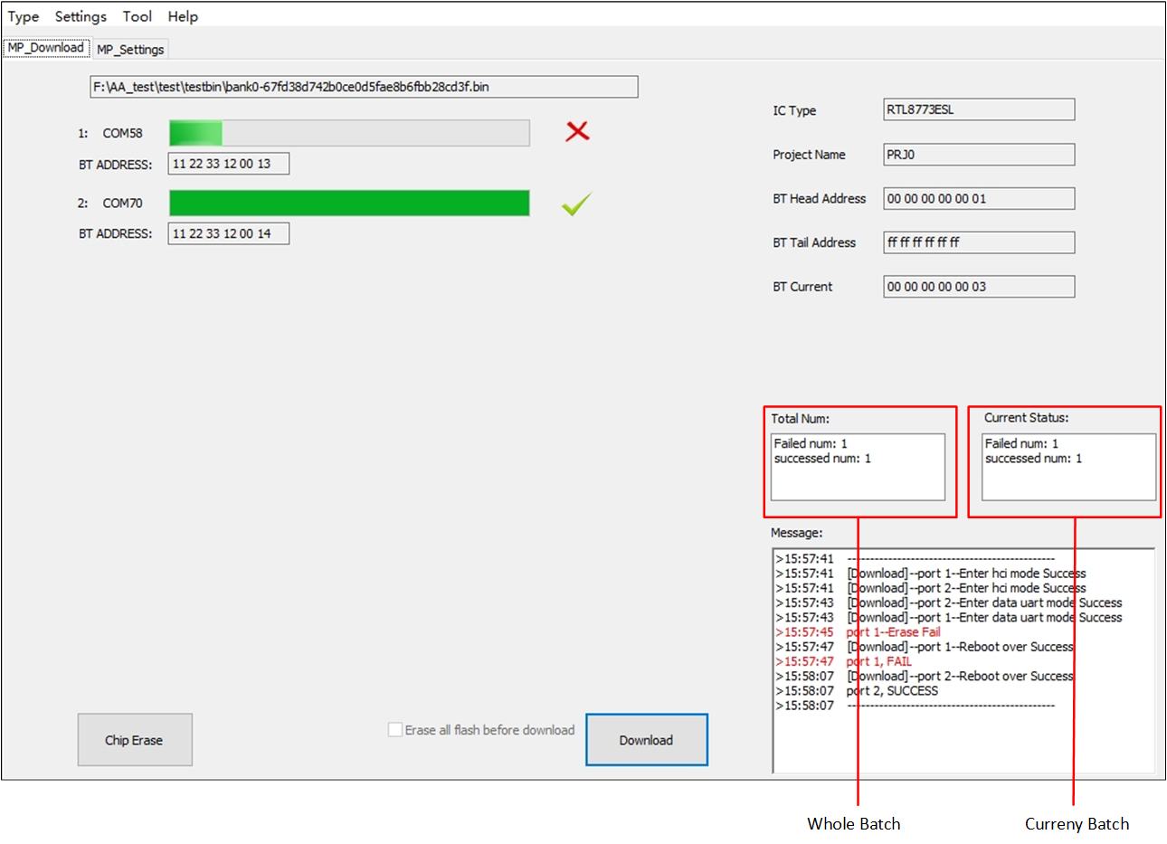
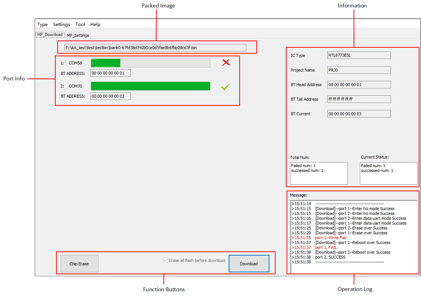
Fail and Success Number after Download
In 'MP Download' mode, you can know fail numbers of download in a whole batch or in current batch, as shown in Fail and Success Number after Download.
Also detailed information will be saved in 'Log' folder which is in MPPGTool.exe's folder, it saved in file whose name is formatted like MPLogYYYY-MM-DD-HH-mm-ss.txt. Take MP Log Format as an example:
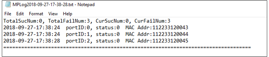
MP Log Format
'TotalSucNum' means success numbers in the whole batch;
'TotalFailNum' means fail numbers in the whole batch;
'CurSucNum' means success numbers in current batch;
'CurFailNum' means fail numbers in current batch.
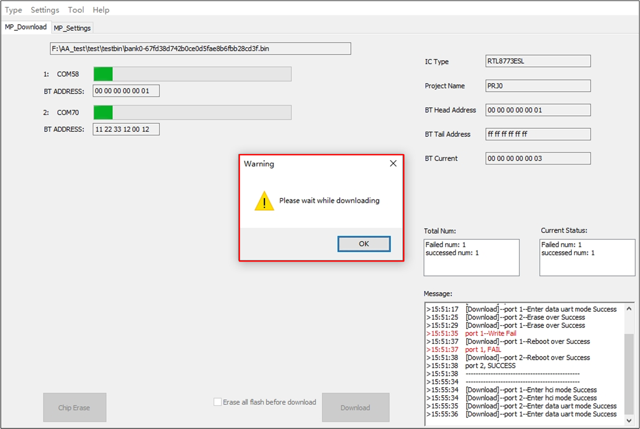
Warning Message
Please don't try to switch to 'Debug mode' or switch to 'MP setting' while downloading image or erase entire chip, otherwise a message box shows 'Please wait while downloading', just like Warning Message.
Download Selection
The commonly flow of download procedure in 'MP mode' is shown in Download Selection.
RD Mode
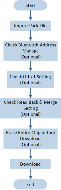
In this mode, you have greater operational control than in 'MP mode'. 'RD mode' interface is shown in RD Download Interface.
RD Download Interface
Load Image & Check Image
-
Add Image(s)
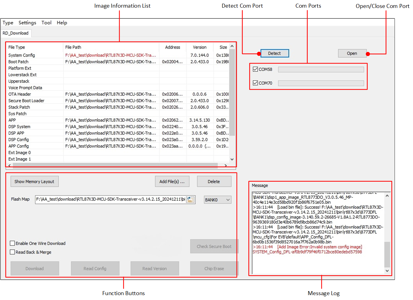
There are two methods to add image(s).
Click Add File(s)... as shown in Select One or Multi Bin Files. An 'Open' dialog will pop up and you can select one or several images at one time.
-
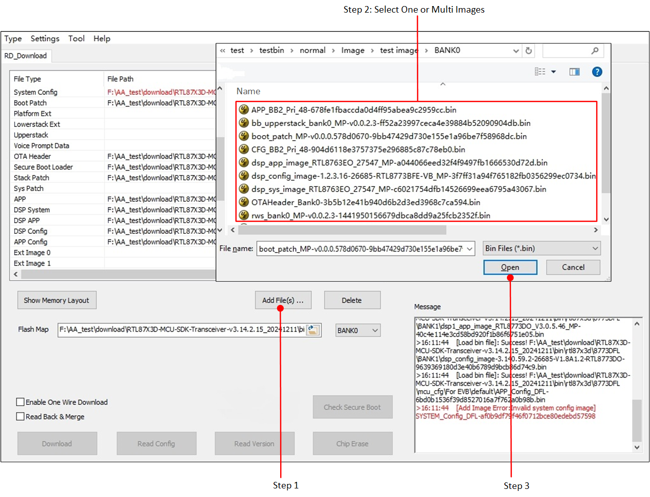
Double click File Path column in each row firstly, a folder icon will show out.You can type in the image path, or click the folder icon to add an image. As shown in Add Bin from File Path.
Select One or Multi Bin Files
Add Bin from File Path
For chips which support configurable flash layout, it is required to import
flash map.iniwhich provides flash address information of sub-images. Ifflash map.iniis not imported, the address info will be marked red in 'Address' column. -
Image Validation Check
After images is loaded, the application will trigger image validation check and address check automatically. Here are some incorrect situations:
-
Inappropriate Bin File
Images of inappropriate type will be marked red, and message log will output 'Inappropriate bin file' (Inappropriate Bin File).
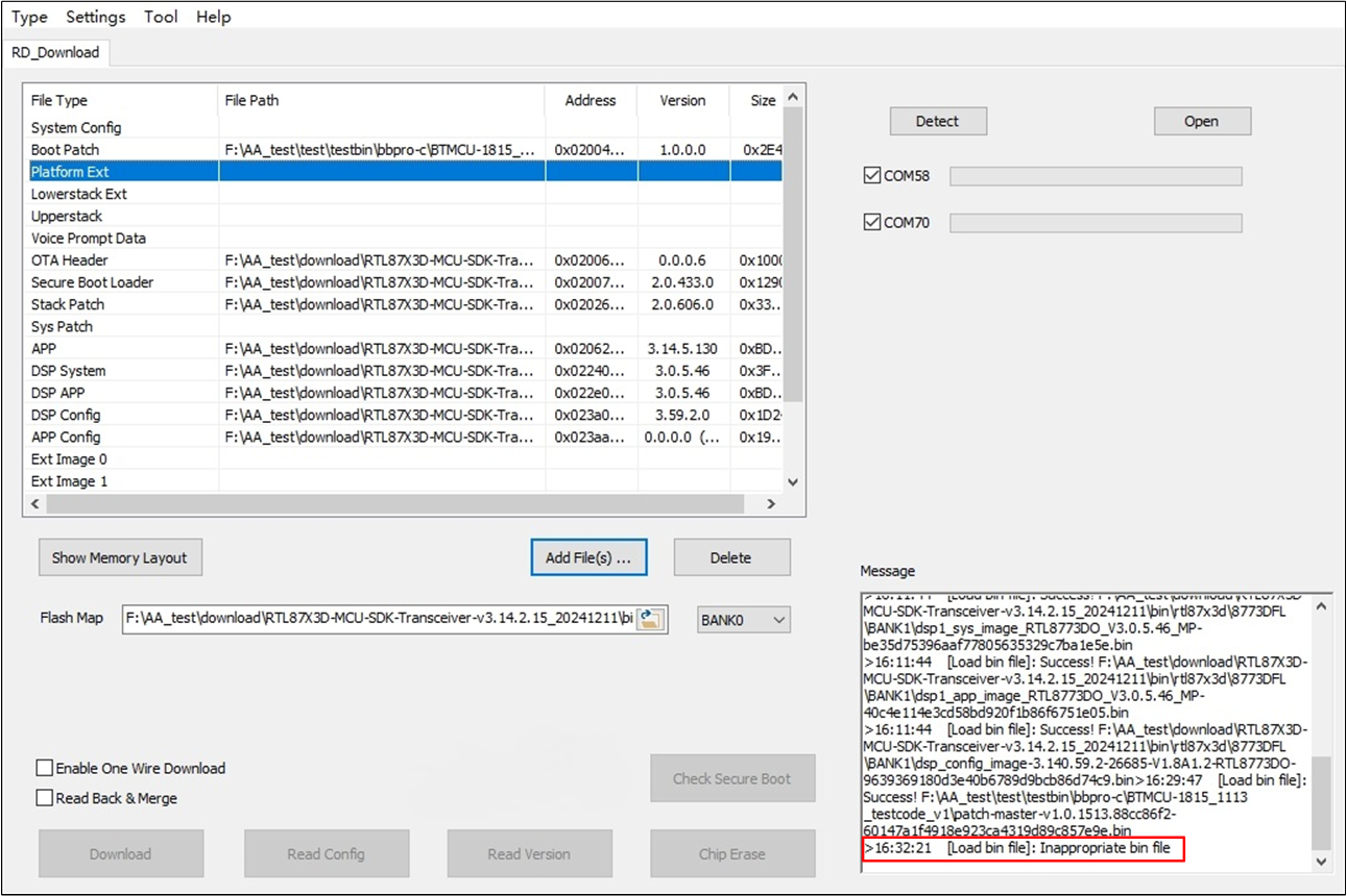
Inappropriate Bin File
-
Valid Address Info
Also, some times in 'Address' column, address info is marked red (Error Address), if this happens, please check address info or enter address manually and if your entered address is incorrect, some hints will show in the log/message area.
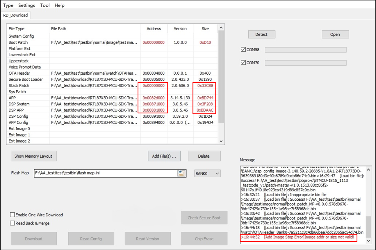
Error Address
-
Detect & Open Port
Click Detect to detect ports' number, the number of ports will show after detection, as shown in Com Port Detection, then choose ports you need and click Open to make these ports ready for operating.
This mode supports simultaneous download or erase operations on up to eight ports.
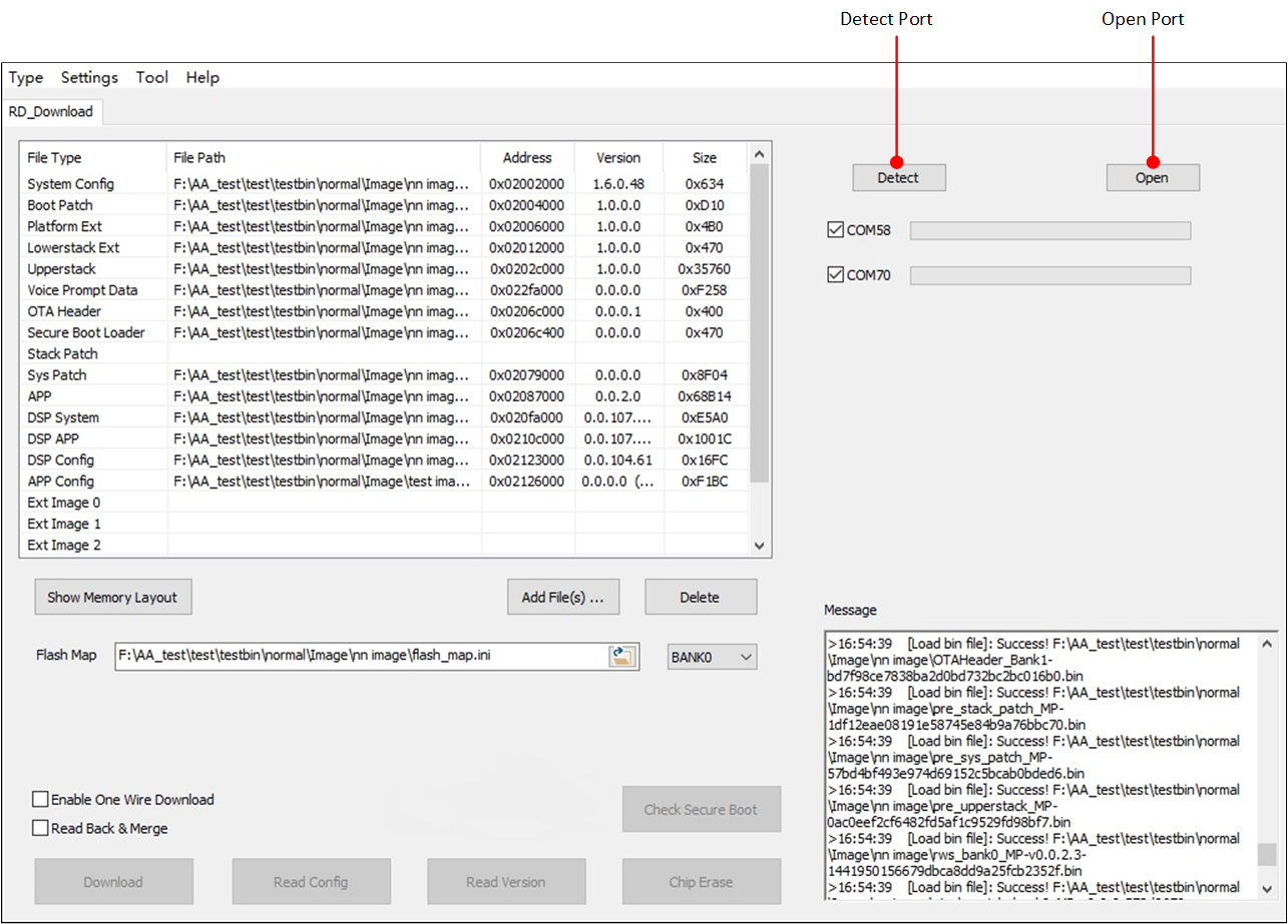
Com Port Detection
If one port is good for operate Download, Read Config , Chip Erase etc., an 'ok' will show out behind the port, otherwise a 'Failed' will show.
If one of the chosen ports shows 'ok', then Download, Read Config and Chip Erase will be able to click. As shown in Open Com Port and Enable Function Button.
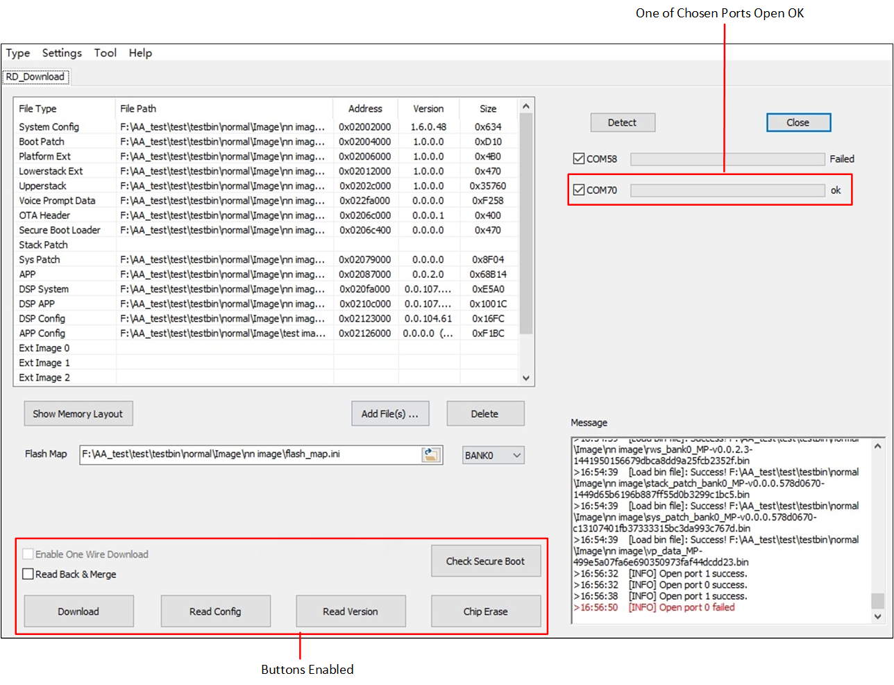
Open Com Port and Enable Function Button
Download
There is an optional operation for you to choose, Read Back & Merge, as shown in RD Download Mode.
And there will be two scenarios:
-
If Read Back & Merge is unchecked, it will erase chip before download. Its procedure will be:
Erase chip (not the entire chip, only the fields you want to write into).
Download bin to chip.
-
If Read Back & Merge is set check, it will read back system configurations and merge by imported bin. Its procedure will be:
Read back parameters and merged with imported bin.
Erase chip (not the entire chip, only the fields you want to write into).
Download bin to chip.
If download procedure succeeds, a 'success' will show behind the port. Otherwise, a 'Failed' will show.
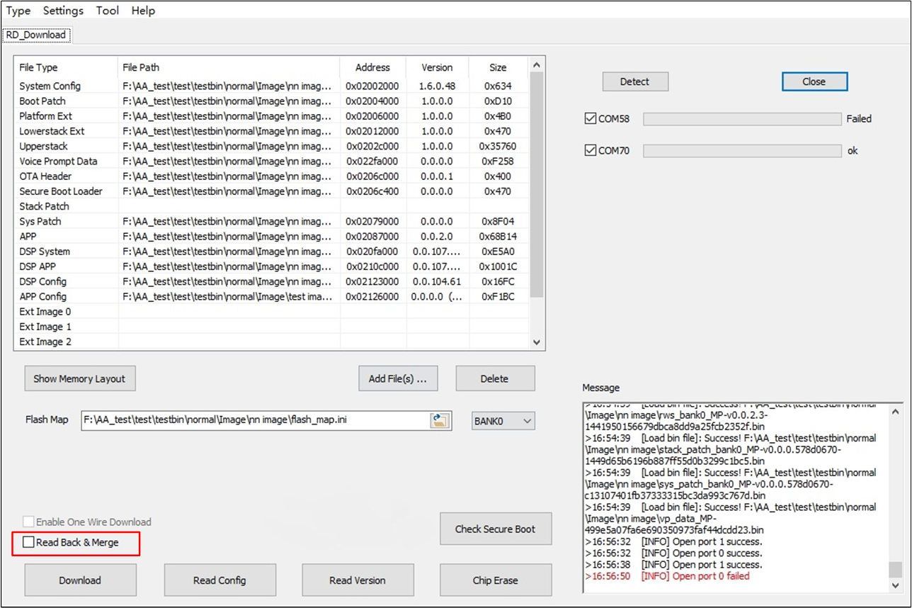
RD Download Mode
Chip Erase
Click Erase to erase the entire chip's flash area, as shown in Erase Entire Chip. If chip erase procedure succeeds, a 'success' will show behind the port, otherwise it will show a 'Failed'.
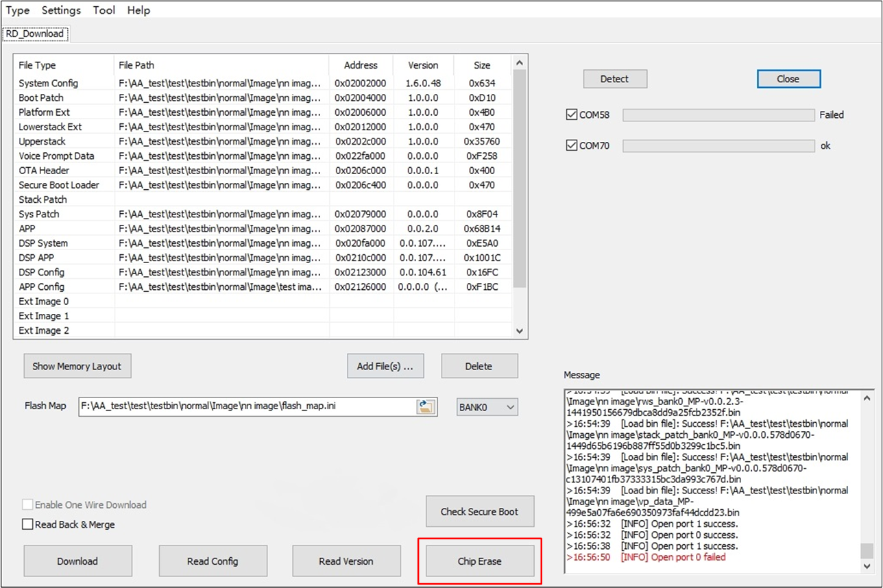
Erase Entire Chip
Read Configuration
It only supports read configuration for one com port at the same time.
Select and open one com port, then click Read Config, if the chip has not programmed download bin before, it will pop out a 'Configuration setting' dialog when read configuration procedure finished, as shown in Read Configuration from Chip.
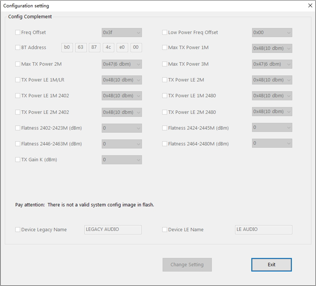
Read Configuration from Chip
If it has already programmed download bin before, and read configuration is successful, it will pop out a 'Configuration setting' dialog (Change Configuration Settings), you can change parameters and check the checkbox you operated before. Then click Change Setting, it will program down changes and close the dialog.
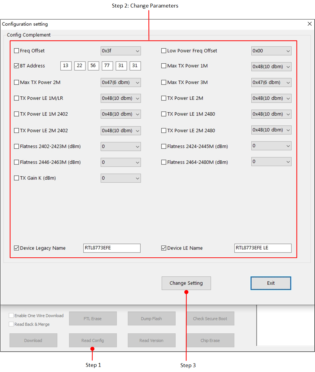
Change Configuration Settings
Check Secure Boot
It only supports check secure boot information for one com port at the same time.
Secure boot information check is a particular function only for some secure chips. It provides functions as follows:
Check Secure Boot
Check SHA Information Read from Efuse
As shown in Check Secure Boot Button, if the IC type you choose at the Guide interface support writing SHA, you will see a Check Secure Boot button in the 'RD mode' interface. While choosing other IC types the button will not be shown.
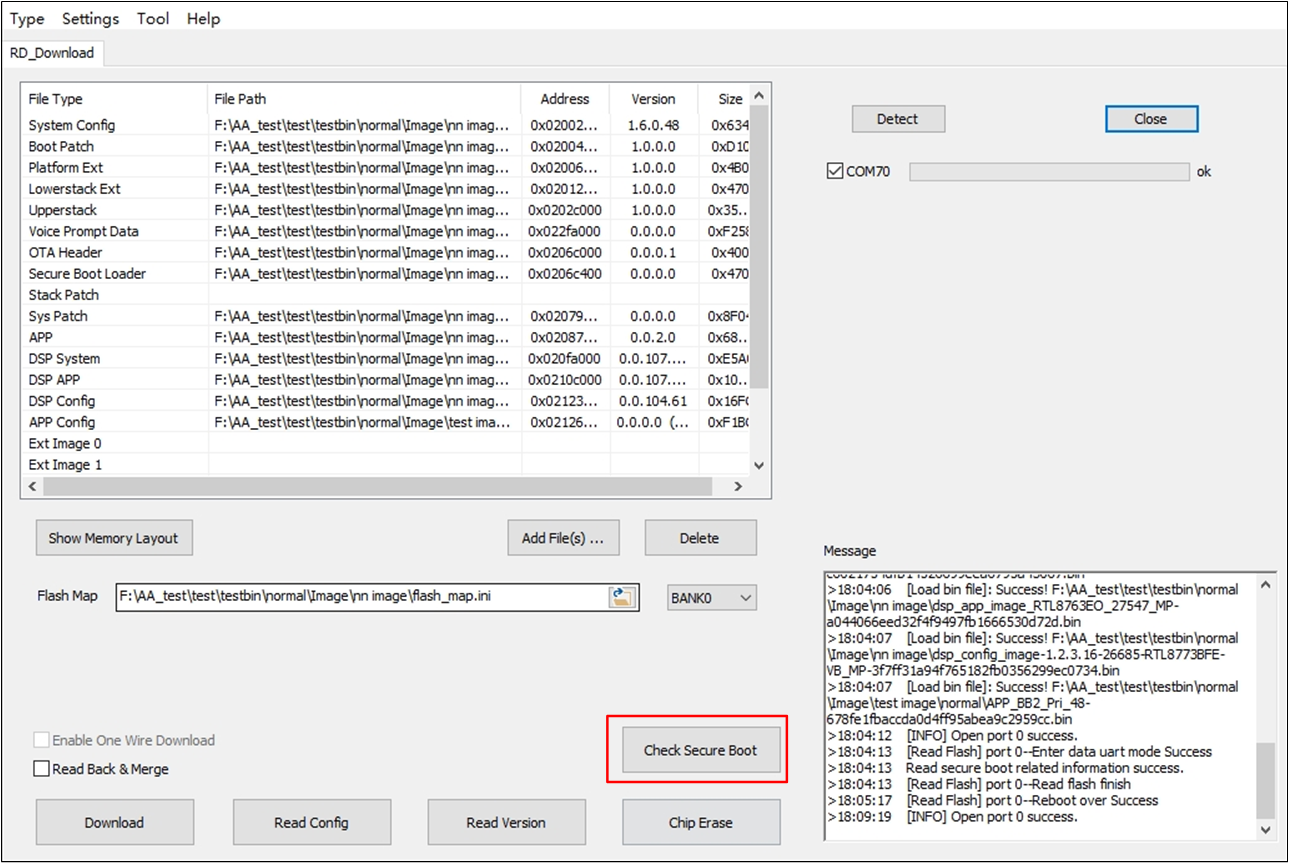
Check Secure Boot Button
Click Check Secure Boot and there will have two results:
-
Secure Boot Disabled
If the chip is not secure boot enabled, the tool will pop up a message box as shown in Secure Boot Disabled.
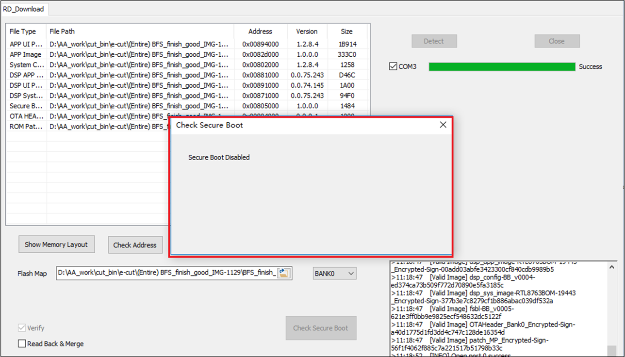
Secure Boot Disabled
-
Secure Boot Enabled
If the chip is secure boot enabled, the tool will read back SHA information from efuse and check valid of the SHA information. There are three scenarios:
-
Empty SHA Information
This scenario indicate that the chip has not be written SHA information into efuse before.
The tool will pop up a message box as shown in Empty SHA Information.
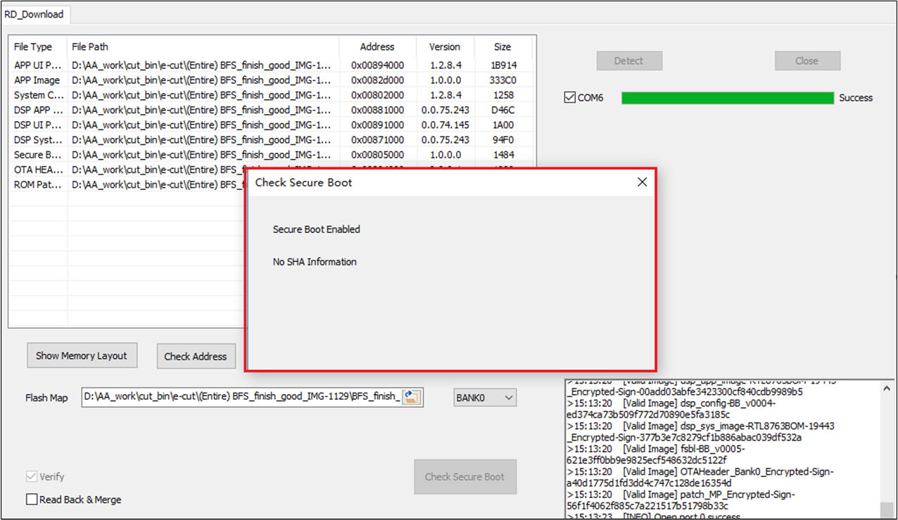
Empty SHA Information
-
Valid SHA Information
If the chip has already be written SHA information into efuse before, tool will check validation of the SHA information read from efuse. If the SHA information read from efuse is valid, tool will show part of them on the message box as shown in Valid SHA Information.
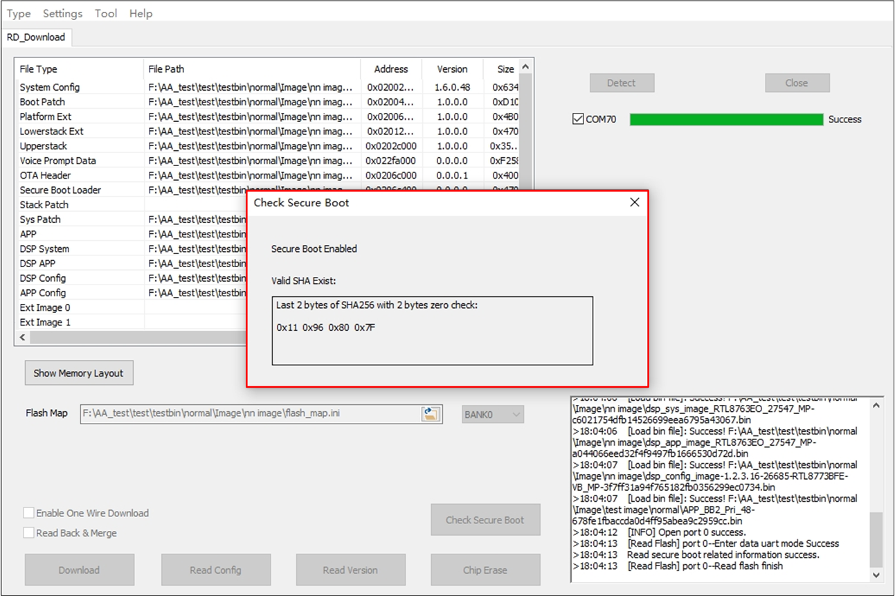
Valid SHA Information
-
Invalid SHA Information
If SHA information read from efuse is not empty and invalid, tool will pop up a message box as shown in Invalid SHA Information.
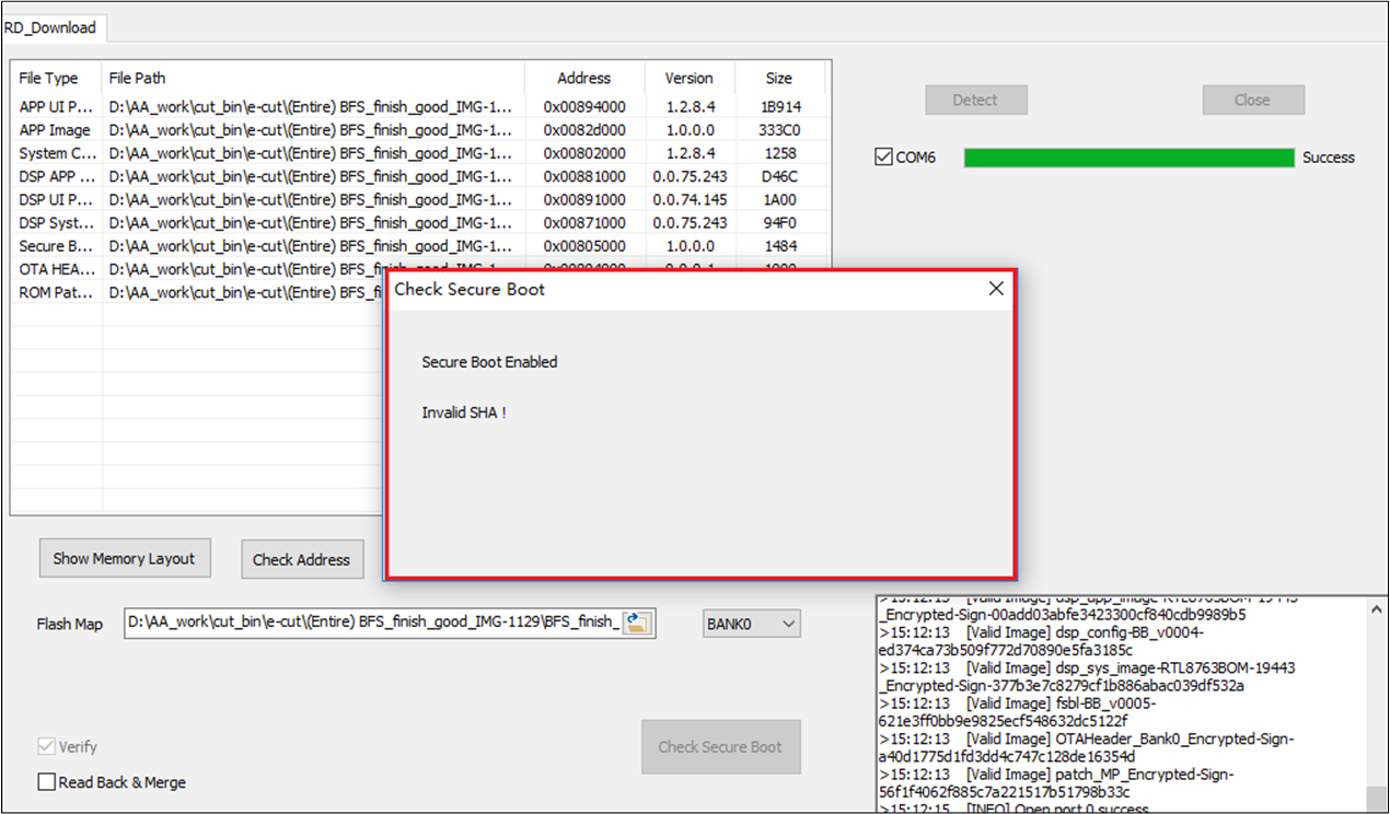
Invalid SHA Information
-
Read Version
It only supports read version for one com port at the same time.
Select and open one com port, then click Read Version, if the chip has already programmed download bin before, and read version is successful, it will pop out an 'Image Info' dialog (Read Version Success).
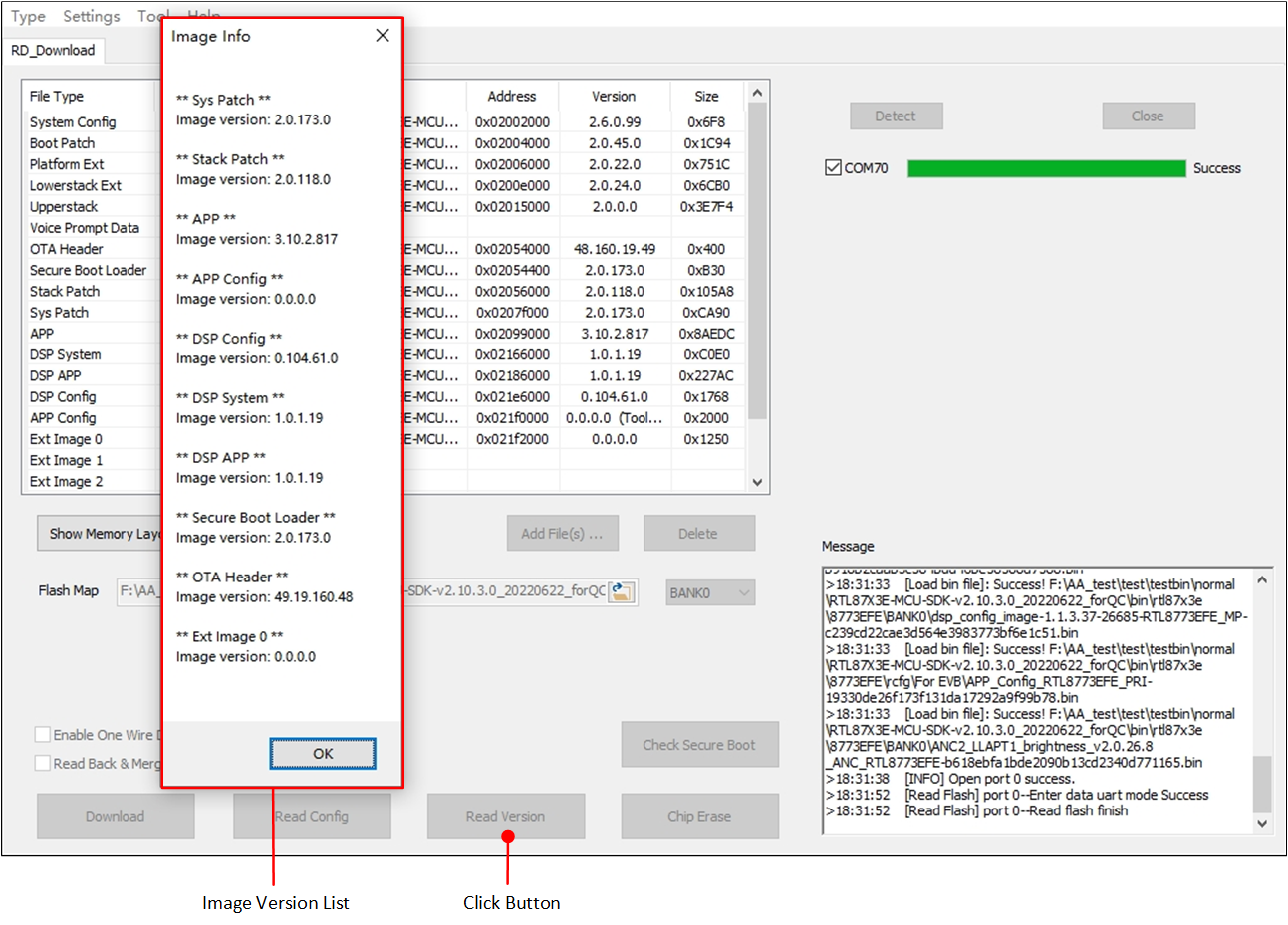
Read Version Success
If the chip has not programmed download bin before, 'Image Info' dialog will show fail message, as shown in Read Version Fail.
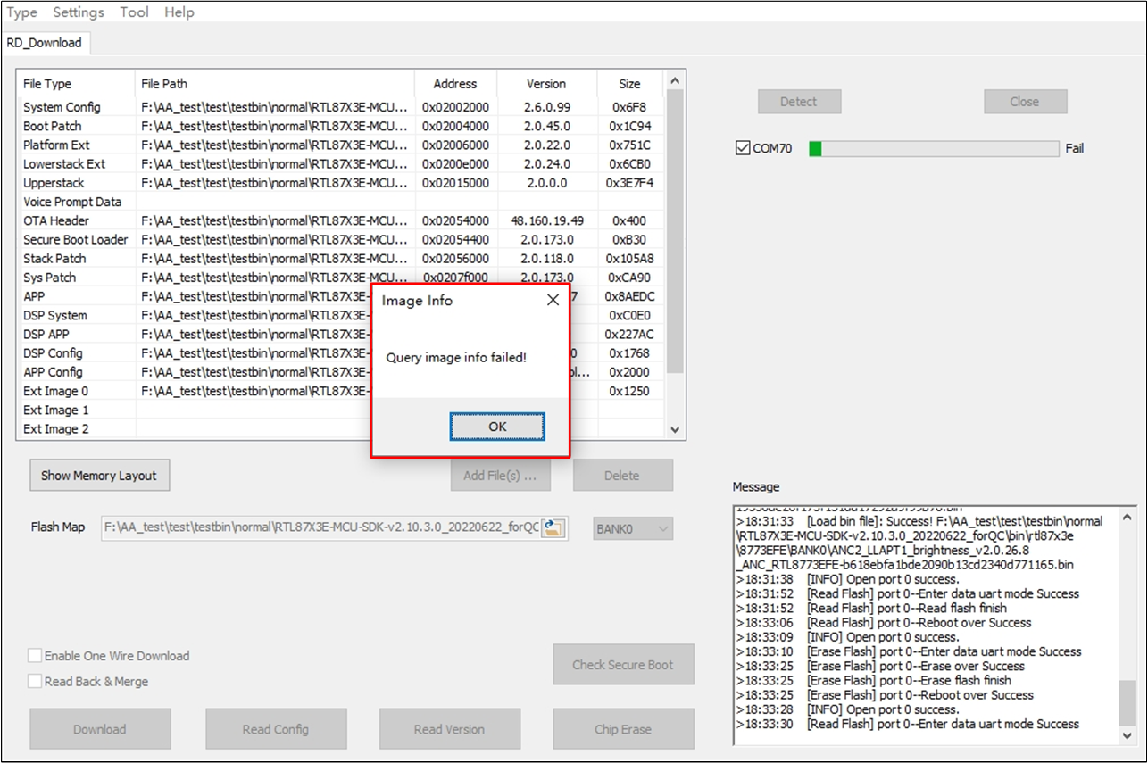
Read Version Fail
One Wire Download
Some IC types of the RTL87X3E and RTL8773D series support the one wire download feature. If this feature is supported, the Enable One Wire Download checkbox will be showed on the UI.
-
In Tab RD_Download, check Enable One Wire Download (Check 'Enable One Wire Download' in Tab 'RD_Download'), after loading the
flash map.iniand image files.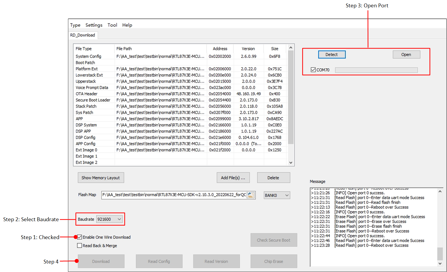
Check 'Enable One Wire Download' in Tab 'RD_Download'
After checking Enable One Wire Download checkbox, an option to select the baud rate will be displayed. Set the appropriate baud rate.
Click Detect and Open to open the port.
After the chosen ports shows 'ok', click Download button to start 'One Wire Download'.
-
EVB wiring of one wire download is as follows:
Connecting one wire Uart adapter.
-
One Wire Uart with EVB Connection.
One wire IO of adapter board is connected to VADP on the EVB.
The GND of the adapter board is connected to the GND of the EVB.
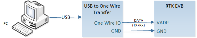
One Wire Uart with EVB Connection
Attention
Can't erase and write boot patch image if Enable One Wire Download checked (Add Boot Patch Image Error).
Chip Erase is not allowed to click in Tab RD_Download if Enable One Wire Download has been checked.
MPPG Tool will send app reset command by clicking Open in one wire download mode, which will trigger SoC to reset to access the one wire download program. If the app on the SoC cannot run normally, and it is not in the state of automatic reset constantly, it is necessary to rely on other ways to make the IC reset to access the one wire download program after clicking Open. After clicking Open, wait for the SoC to reset to access the one wire download mode, the timeout is set to 20s.
Recommended to have two bank images burned before switching to one wire download mode.
-
The supported baud rates of the chip is dependent on the capacitance. Please choose the chip's supported baud rate.
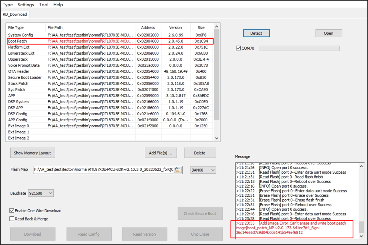
Add Boot Patch Image Error
Appendix
System Environment
MPPG Tool supports win7 system and win10 system.
MPPG Tool will detect all serial ports in the system. Irrelevant COM ports irrelevant may cause open failure. Please turn off irrelevant ports before mass production.
-
How to turn off irrelevant ports:
-
As shown in Open Device Manager, press 'Win+X' on the keyboard, and select Device Manager from the context menu.
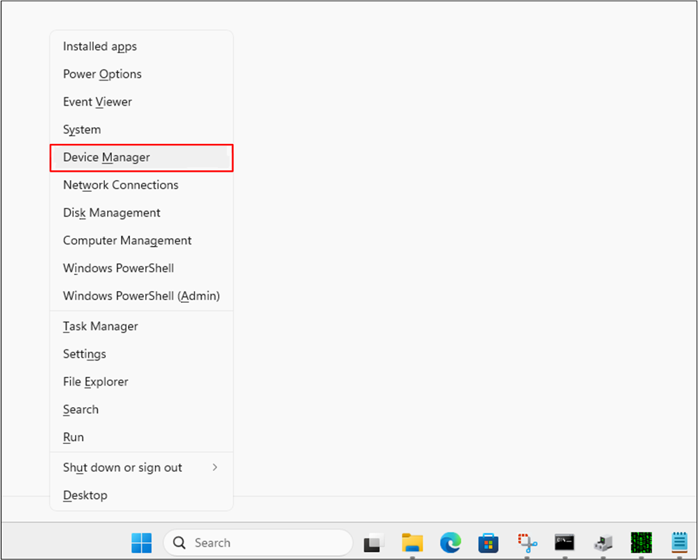
Open Device Manager
-
As shown in Forbid Irrelevant COM, other irrelevant COM ports in 'Ports'.
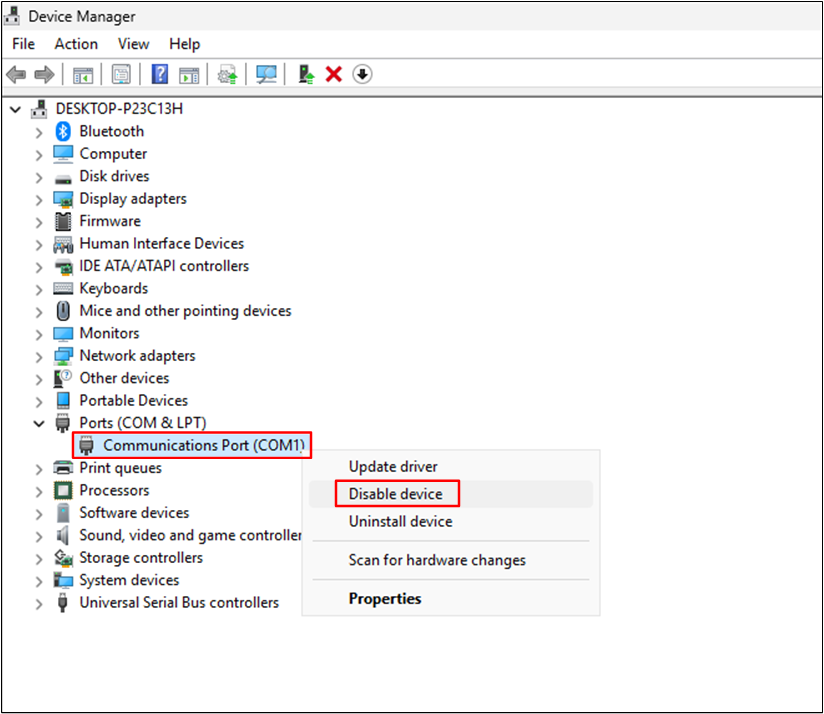
Forbid Irrelevant COM
-
Connection Scenarios
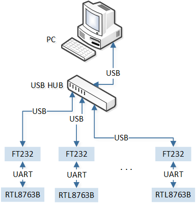
One-to-Many Wiring
If downloading though one-to-many way via USB HUB, please make sure sufficient power supply to ensure stable downloading. We strongly suggest to use USB HUB with external power source (One-to-Many Wiring).
EVB Wiring
Make sure the P2_0 is ground connection.
-
Shortening UART_TXD and HCI_RX with jumper cap;
Shortening UART_RXD and HCI_TX with jumper cap.
Reset the EVB before PG.
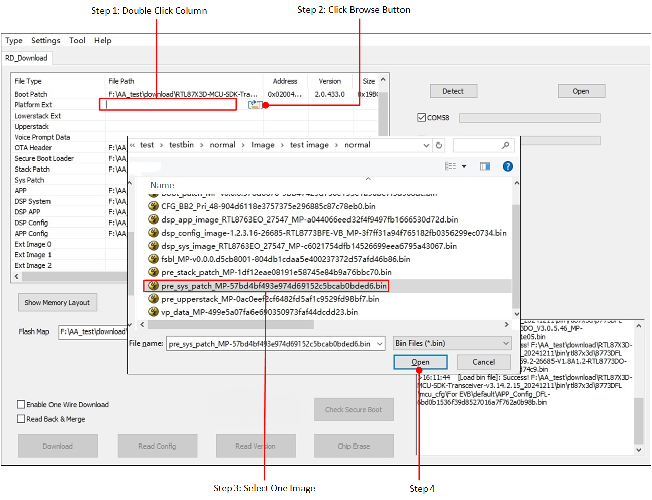
Suggested Flow
The suggested flow is as follows:
Chip erase.
Attention
If some parameters need to be maintained (e.g. 'Bluetooth Address', 'Freq Offset' configured in previous stage), skip this step! Simply check Read Back & Merge and move on to step2.
Download.
Factory reset.