MPPG Tool Chain
This document introduces useful tool chain which is integrated in MPPG Tool for Realtek Bluetooth chip.
The major tool to introduce is 'Pack Tool', which is used to generate pack image packet for chip flash programming or OTA.
For chips that support configurable flash layout, 'Flash Map Generator' and 'OTA Header Generator' are also introduced. These functions are mainly applied for SDK customers.
Additionally, supplementary tools are provided, including 'One-Click Pack for OTA' and 'Erase 8K Reserved Flash'.
Pack
Select IC
IC type should be selected at the first usage, as shown in IC Type Selection.
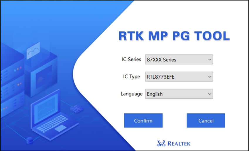
IC Type Selection
Select IC series and IC type which you are going to use, and then click Confirm to enter MPPG Tool dialog.
Please make sure correct IC series and IC type is selected, or there may have error in pack procedure.
Select Pack Type
Pack Tool is integrated in 'Tool' menu on MPPG Tool dialog (as shown in Select Pack Type).
Two pack types are supported in Pack Tool: 'For MP' and 'For OTA'.
Different type supports different sub images in pack procedure, but the operating buttons and packing logic are the same.
'For MP' type is used to generate image packet for downloading procedure, it supports almost all sub images which the selected IC supports.
'For OTA' type is used to generate image packet for OTA procedure, it only supports sub images which can be OTA for the selected IC.
Select pack type which you are going to use to enter Pack Tool dialog.
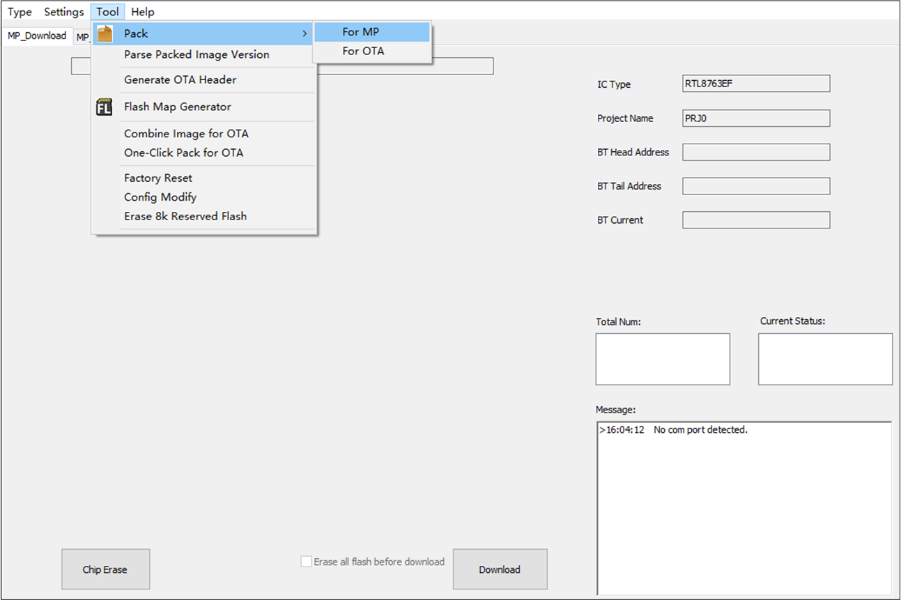
Select Pack Type
Add Sub Images
There are two ways to add sub images:
Add single sub image through image list column.
Add multi-images at one time by clicking Add File(s).
For chips that support configurable flash layout, it is required to load flash map.ini.
Load Flash Map
For chips that support configurable flash layout, it is required to import flash map.ini which provides flash address information of sub images (Shown in Import Flash Map File). The sub image address will be shown after importing flash map.ini, and image address cannot be modified.
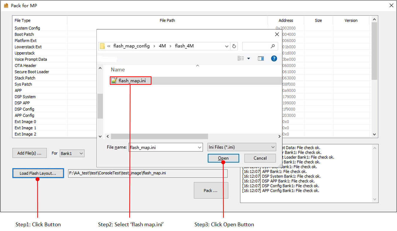
Import Flash Map File
For chips which do not support configurable flash layout, it do not need to load flash map.ini. The sub image address is fixed and cannot be modified.
Add Single Image
Single sub image can be added in following way:
Find the file type of the sub image to be added and double click the place in 'File Path' column to switch into edit mode.
Click the folder icon (Shown in Add File Path) to add sub image. Image File Select shows 'Image File Select' dialog.
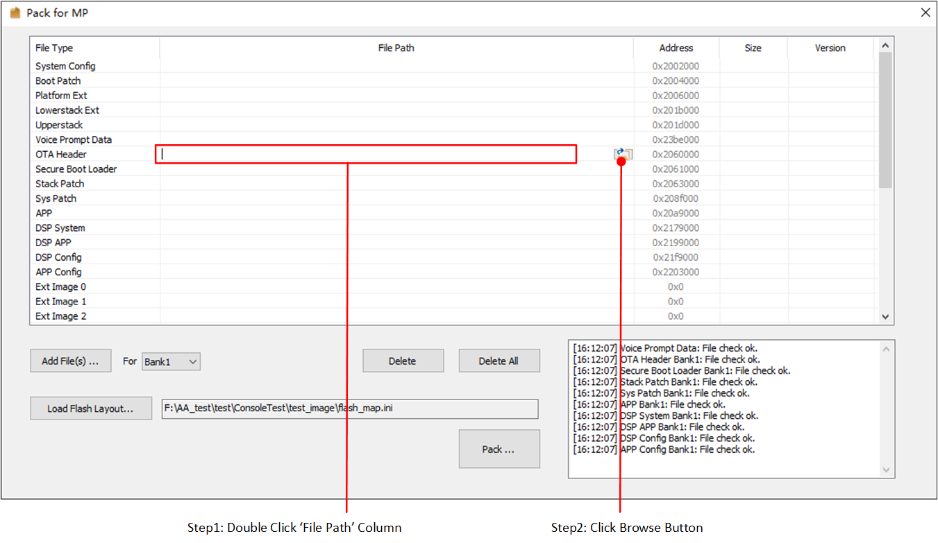
Add File Path
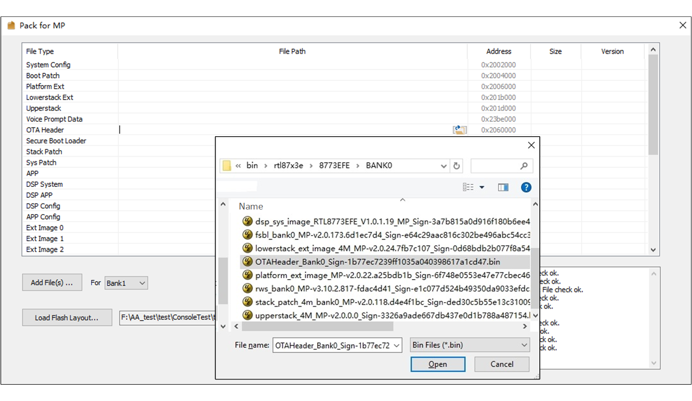
Image File Select
Add Multi-Images
For chips that support configurable flash layout, it is suggest to select OTA bank before add multi-images. The default OTA bank is 'Bank0'. The sub images will be added in the selected bank for packing.
Click Add File(s) to add more than one files at one time, however, adding files in this way will firstly clear all the old files in the list and then add new files (Shown in Add Multi-Image Files to List).
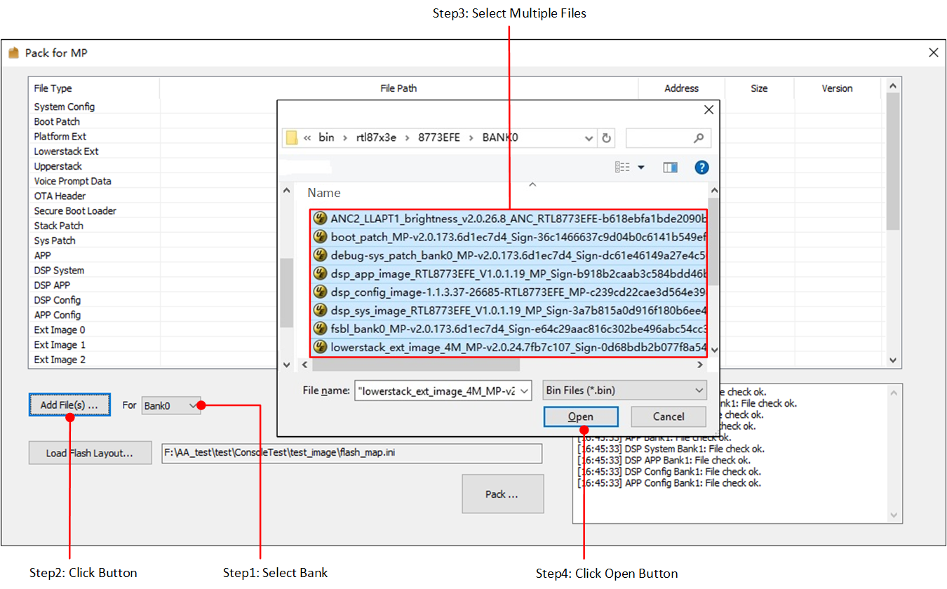
Add Multi-Image Files to List
Image Check
The Pack Tool will check whether the selected images are valid, e.g. MD5 check is necessary for all the selected files. Sub image files are also need to check file type, file length, file version, etc. (Shown in File Check Error & Success). The check result will be shown in message box. If check failed, the column color will be set to red.
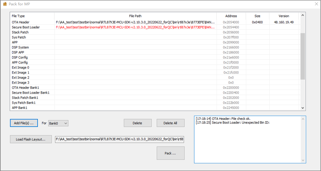
File Check Error & Success
Remove Sub Images
If one sub image is mistaken added into the image list, select it in the image list and click Delete to remove it (Shown in Remove Sub Image).
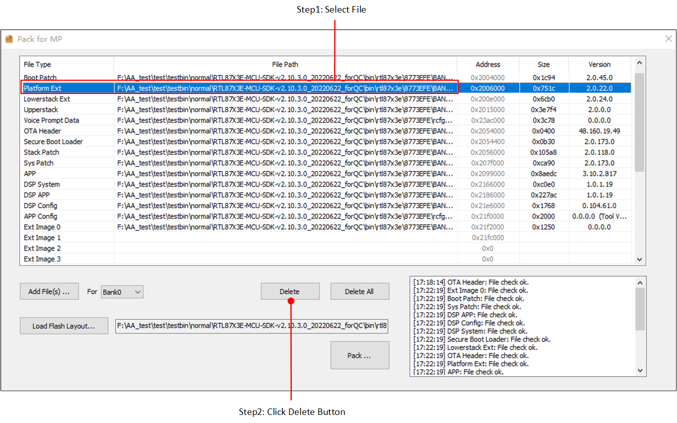
Remove Sub Image
You can also delete all images in the image list at one time by clicking Delete All.
Generate a Packet
After building a complete image list, click Pack... to generate a packet. Choose a saving path for the packet and type in the custom name in the pop-up dialog, and then click Save as shown in Save Packet in Custom Path.
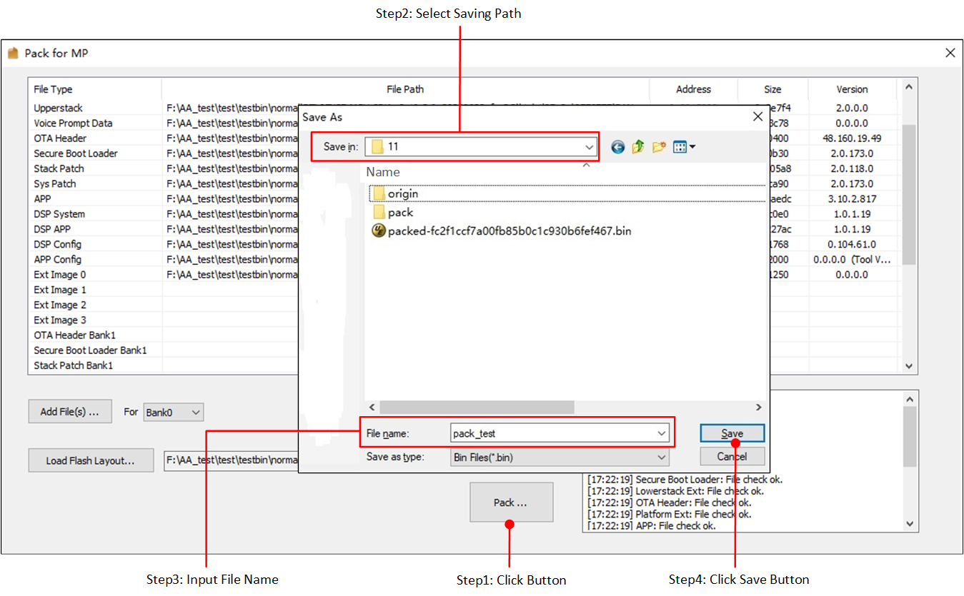
Save Packet in Custom Path
The packet will be stored in the custom path named as CustomName-MD5.bin (Shown in Saved Packet). MD5 is the MD5 value for the whole packet file.
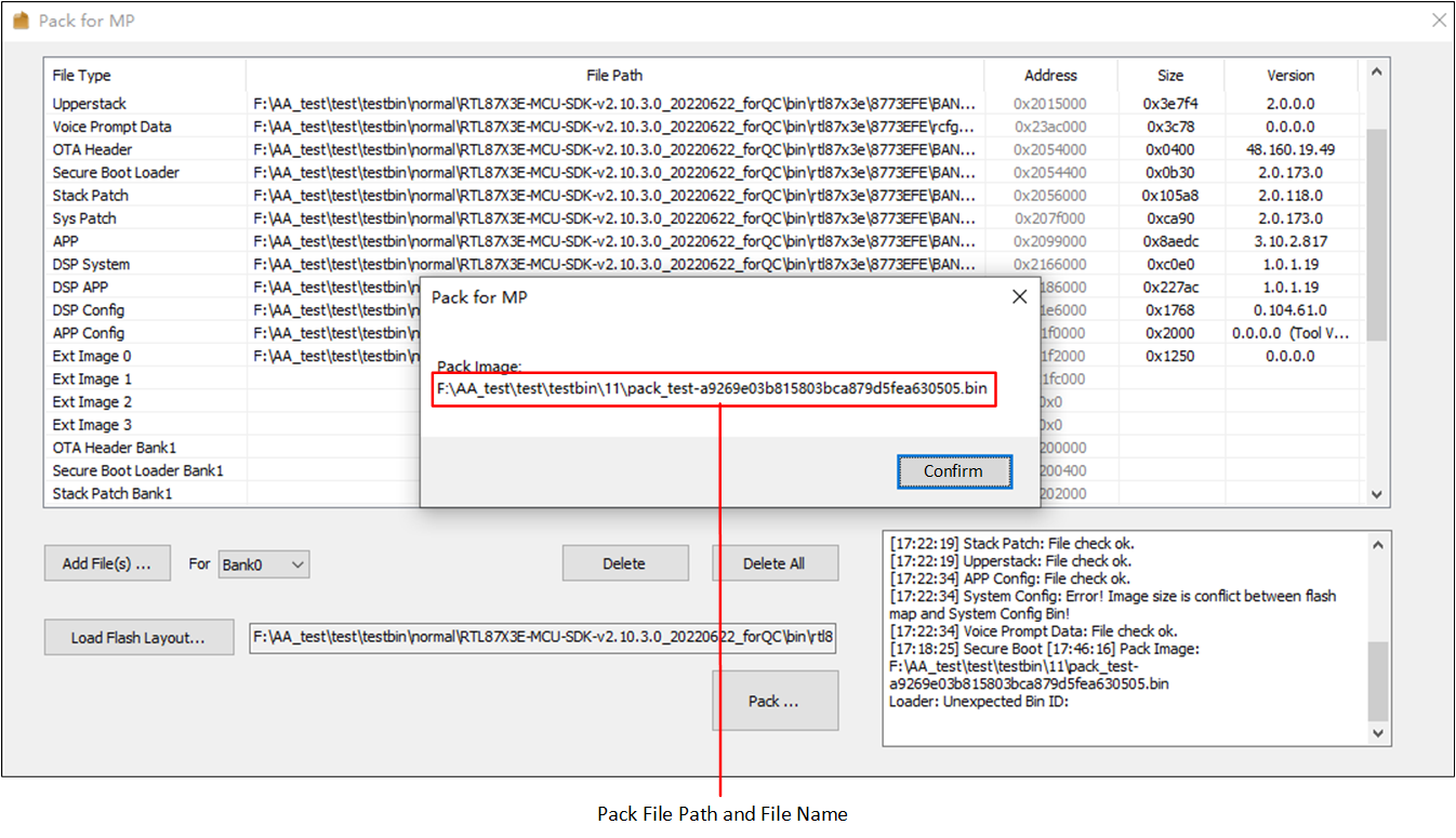
Saved Packet
If the packet file cannot be generated correctly, there will be error message. Change sub bin files' selection according to the message and click Pack... again to generate packet file correctly.
Generate OTA Header Bin
For chips that support configurable flash layout, tool chain provides OTA Header generator tool for 'OTA Header bin' generating.
Click menu to open the 'Generate OTA Header' dialog and generate OTA header bin (Shown in Open Generate OTA Header Dialog).
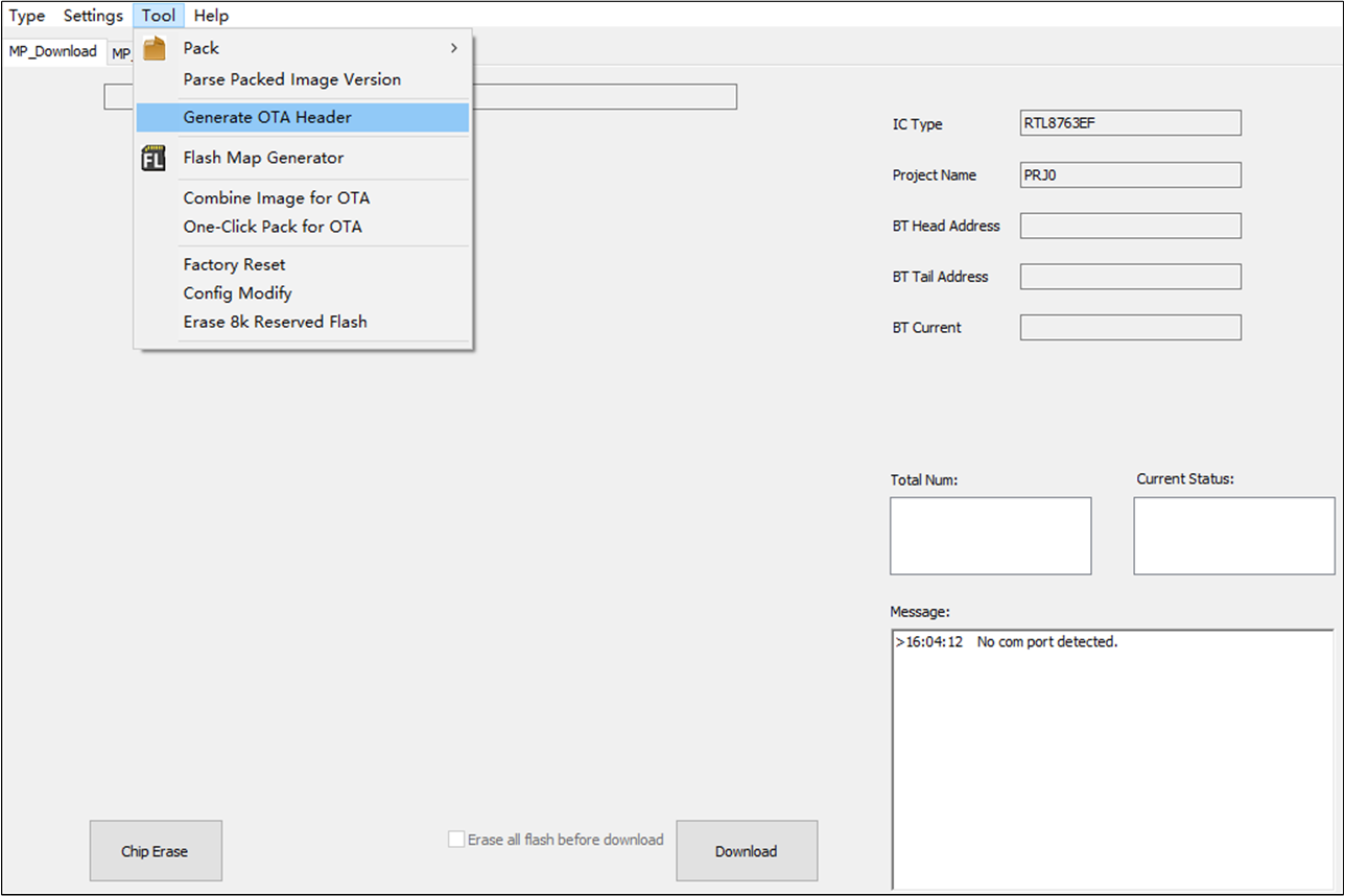
Open Generate OTA Header Dialog
Click Load Flash Layout... to load flash map.ini and click Load RSA Key... to load a RSA key for OTA Header. The address and size of all type files in the list are configured according to the loaded flash map.ini and cannot be modified.
After configuring all the properties, click Generate... to generate OTA Header bin (Shown in Generate OTA Header Dialog).
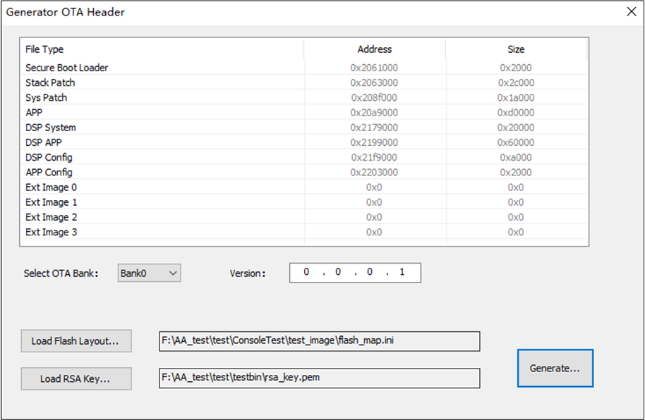
Generate OTA Header Dialog
Generate Flash Map
For chips that support configurable flash layout, tool chain provides Flash Layout generator tool for flash map.ini generating.
Click menu to open the 'Flash Map Generate' dialog and generate flash map.ini (Shown in Open Flash Map Generate Dialog).
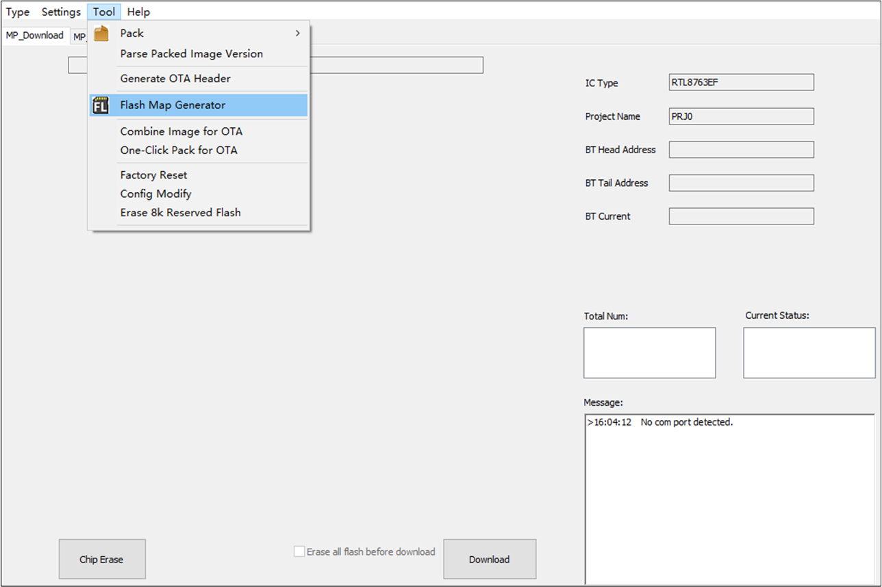
Open Flash Map Generate Dialog
Flash Map Generate dialog is shown in Flash Map Generate Dialog. Configure the whole flash layout in 'High Level Type' list and configure layout for bank0/bank1 in 'OTA File Type' list after selecting Flash Size combo box. Multi-image header size is provided in Image Header Size combo box.
You can also import an existing flash map.ini by clicking Import... and then modify layout base on it.
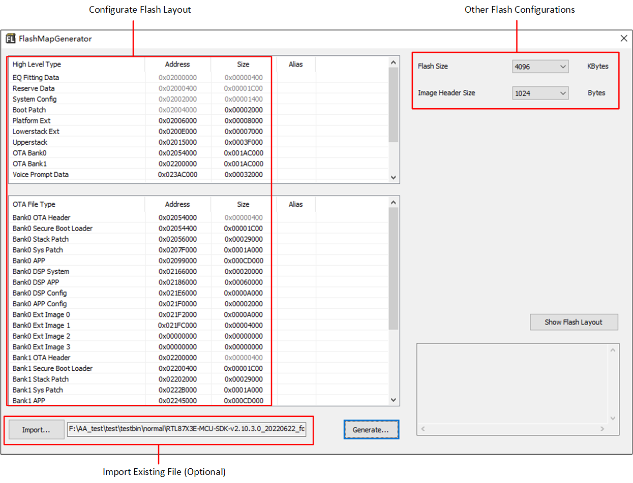
Flash Map Generate Dialog
If there are some memory overlap in the flash layout, the overlap file types will be set to other colors and error message will be shown in message box (Shown in Memory Overlap).
The overlapped file type should be configured correct address or size to resolve memory conflict.
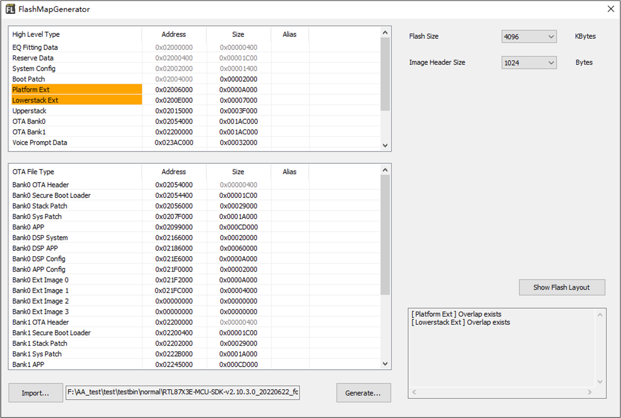
Memory Overlap
The Flash Map Generate Tool also provides a function to show memory layout. Using it to help check if there is any memory overlap in current build.
Choose a correct flash size before using it, make sure the selected size is match with the using flash. Then click Show Flash layout to show memory layout (Shown in Show Memory Layout).
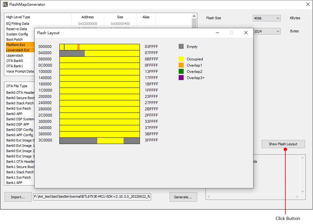
Show Memory Layout
After configuring all the properties correctly, click Generate... to generate a flash map.ini file after configuring all the layout. The generated file can be used in Pack Tool/MPPG Tool/MP Tool.
One-Click Pack for OTA
Please following the steps below:
Put bin files and
flash map.iniinto specified sub-folders of 'OneClickPack' folder.
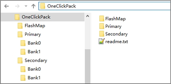
Fixed Folder Layout for One-Click Pack
Click menu .
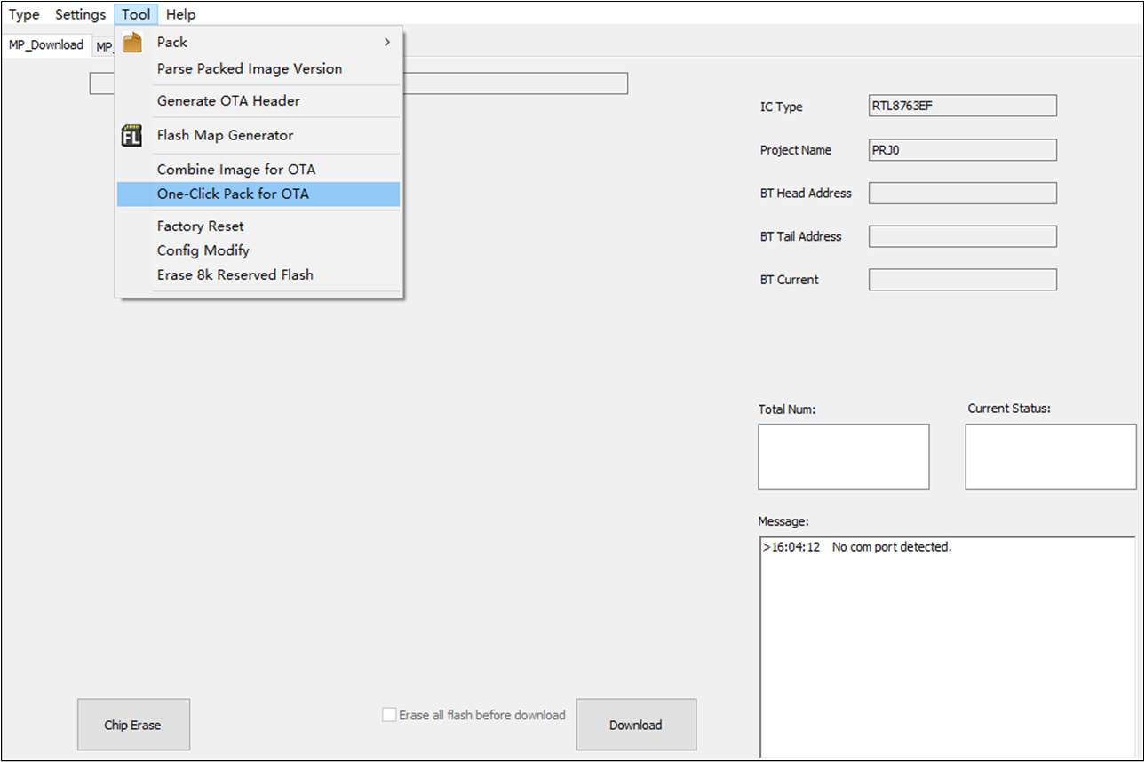
Open One-Click Pack Dialog
Load 'OneClickPack' folder and click Auto Pack.
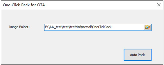
Auto Pack
Erase 8K Reserved Flash
The tool chain provides Erase Reserved Flash function for specific chips, erasing the reserved 8k block in flash memory.
This action will erase the reserved 8k block in flash memory, and the parameter could not be recovered.
Click menu to open the 'Erase Reserved Flash' dialog.
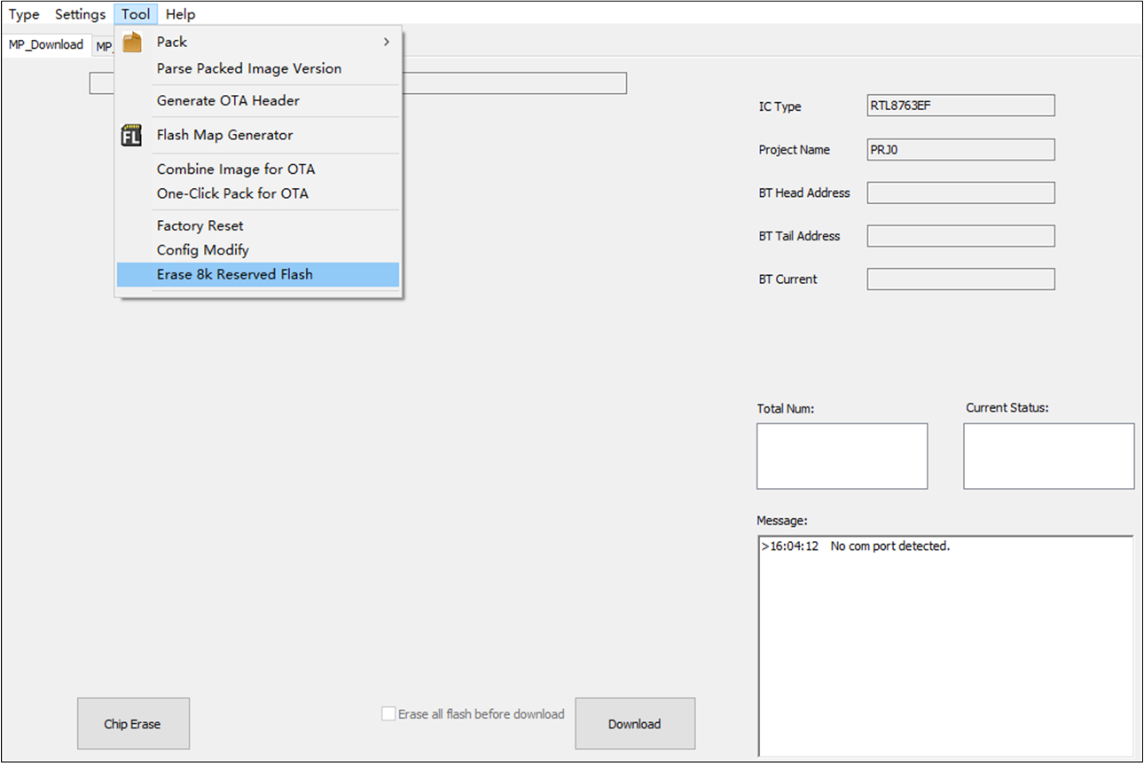
Open Erase Reserved Flash Dialog
Click Erase 8K Reserved Flash in 'Erase Reserved Flash' dialog.
The warning message box will pop up twice after Erase 8K Reserved Flash is clicked.
Before erase job started, the user needs to confirm the warning message twice.
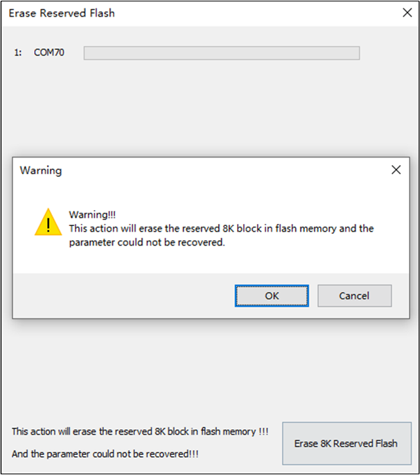
'Erase 8K Reserved Flash' Button and Warning Message Box