Analog Microphone
This sample code collects AMIC (Analog Microphone) data and encodes it into PCM voice data via CODEC.
The AMIC collects analog voice data, encodes it through CODEC, sends it to the I2S receive FIFO, and uses DMA to transfer the data to UART.
The PC receives the data transmitted by UART through a serial port assistant, uses audio parsing software (such as Audacity) to analyze the data, and plays the recorded voice.
The AMIC CODEC process is shown as follows.
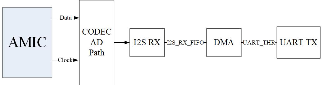
CODEC AMIC Process
Requirements
The sample supports the following development kits:
Hardware Platforms |
Board Name |
|---|---|
RTL8752H HDK |
RTL8752H EVB |
For more requirements, please refer to Quick Start.
Wiring
EVB connects to the AMIC module, connecting H0 to 1.8V, GND to GND, P2_6 to MIC_P, and P2_7 to MIC_N;
EVB connects to the FT232 module, connecting P3_2 (UART TX) to RX on the FT232, and P3_3 (UART RX) to TX on the FT232.
Building and Downloading
This sample can be found in the SDK folder:
Project file: board\evb\io_sample\CODEC\AMIC\mdk
Project file: board\evb\io_sample\CODEC\AMIC\gcc
Please follow these steps to build and run the example:
Open sample project file.
To build the target, follow the steps listed on the Generating App Image in Quick Start.
After a successful compilation, the app bin
app_MP_xxx.binwill be generated in the directorymdk\binorgcc\bin.To download app bin into EVB board, follow the steps listed on the MP Tool Download in Quick Start.
Press reset button on EVB board and it will start running.
Experimental Verification
Preparation Phase
-
Launch a PC terminal like PuTTY or UartAssist, connect to the used COM port, and make the following UART settings:
Baud Rate: 3000000
8 Data Bits
1 Stop Bit
No Parity
No Hardware Flow Control
Launch the audio analysis software.
Testing Phase
Start recording until completion. The collected audio data, encoded as PCM data by Codec, is sent to the PC terminal via UART.
Copy the decoded data from the PC terminal into a new ASCII bin document.
Use the audio analysis software to view the decoded audio waveform, and you can also play the audio.
Code Overview
This chapter will be introduced according to the following several parts:
Peripheral initialization will be introduced in chapter Initialization.
Functional implementation after initialization will be introduced in chapter Function Implementation.
Source Code Directory
Project directory:
sdk\board\evb\io_sample\CODEC\AMICSource code directory:
sdk\src\sample\io_sample\CODEC\AMIC
Source files are currently categorized into several groups as below.
└── Project: codec_amic
    └── secure_only_app
        └── include
            ├── app_define.h
            └── rom_uuid.h
        ├── cmsis                    includes CMSIS header files and startup files
            ├── overlay_mgr.c
            ├── system_rtl876x.c
            └── startup_rtl876x.s
        ├── lib                      includes all binary symbol files that user application is built on
            ├── rtl8752h_sdk.lib
            ├── gap_utils.lib
            ├── ROM.lib
            └── adc.lib
        ├── peripheral               includes all peripheral drivers and module code used by the application
            ├── rtl876x_rcc.c
            ├── rtl876x_pinmux.c
            ├── rtl876x_nvic.c
            ├── rtl876x_gdma.c
            ├── rtl876x_uart.c
            ├── rtl876x_codec.c
            └── rtl876x_i2s.c
        ├── profile
        └── app                      includes the ble_peripheral user application implementation
            └── main.c
Initialization
When the EVB reset, the "main" function is executed, following these steps:
int main(void)
{
    extern uint32_t random_seed_value;
    srand(random_seed_value);
    __enable_irq();

    codec_demo();

    while (1)
    {
        ;

    }
}
In codec_demo, it includes processes such as PAD/PINMUX settings, I2S peripheral initialization, UART peripheral initialization, DMA peripheral initialization, and CODEC peripheral initialization.
void codec_demo(void)
{
    board_codec_init();
    board_uart_init();
    driver_i2s_init();
    driver_uart_init();
    driver_gdma_init();
    driver_codec_init();
    I2S_Cmd(I2S0, I2S_MODE_TX | I2S_MODE_RX, ENABLE);
    GDMA_Cmd(GDMA_Channel_AMIC_NUM, ENABLE);
}
board_codec_init is the PAD and PINMUX settings for AMIC related pins, including the following process:
Configure PAD: set pin, SW mode, NOT PowerOn, internal pull-none. The H0 pin outputs high, while other pins are disabled.
void board_codec_init(void)
{
    Pad_Config(H_0, PAD_SW_MODE, PAD_NOT_PWRON, PAD_PULL_NONE, PAD_OUT_ENABLE, PAD_OUT_HIGH);
    Pad_Config(P2_6, PAD_SW_MODE, PAD_NOT_PWRON, PAD_PULL_NONE, PAD_OUT_DISABLE, PAD_OUT_HIGH);
    Pad_Config(P2_7, PAD_SW_MODE, PAD_NOT_PWRON, PAD_PULL_NONE, PAD_OUT_DISABLE, PAD_OUT_LOW);
}
board_uart_init is the PAD and PINMUX settings for UART-related pins, including the following steps:
Configure PAD: Set the pins, PINMUX mode, PowerOn, and internal pull-up. The TX pin outputs high, and the RX pin is disabled.
Configure PINMUX: Assign the pins to UART0_TX and UART0_RX respectively.
void board_uart_init(void)
{
    Pad_Config(UART_TX_PIN, PAD_PINMUX_MODE, PAD_IS_PWRON, PAD_PULL_UP, PAD_OUT_ENABLE, PAD_OUT_HIGH);
    Pad_Config(UART_RX_PIN, PAD_PINMUX_MODE, PAD_IS_PWRON, PAD_PULL_UP, PAD_OUT_DISABLE, PAD_OUT_LOW);

    Pinmux_Config(UART_TX_PIN, UART0_TX);
    Pinmux_Config(UART_RX_PIN, UART0_RX);
}
driver_i2s_init is the initialization of the I2S peripheral, including the following steps:
Enable the RCC clock.
Set the I2S clock source to 40MHz, and the sample rate to 16kHz.
Configure it to master device mode, with mono output.
void driver_i2s_init(void)
{
    RCC_PeriphClockCmd(APBPeriph_I2S0, APBPeriph_I2S0_CLOCK, ENABLE);

    I2S_InitTypeDef I2S_InitStruct;
    I2S_StructInit(&I2S_InitStruct);
    I2S_InitStruct.I2S_ClockSource      = I2S_CLK_40M;
    I2S_InitStruct.I2S_DataFormat       = I2S_Mode;
    I2S_InitStruct.I2S_ChannelType      = I2S_Channel_Mono;
    I2S_InitStruct.I2S_DeviceMode       = I2S_DeviceMode_Master;
    I2S_InitStruct.I2S_RxWaterlevel     = 0x4;
    /* BCLK = 40MHz*(I2S_BClockNi/I2S_BClockMi) = Sample Rate * 64BCLK/sample */
    I2S_InitStruct.I2S_BClockMi         = 0x186A;
    I2S_InitStruct.I2S_BClockNi         = 0xA0;

    I2S_Init(I2S0, &I2S_InitStruct);
}
driver_uart_init is the initialization of the UART peripheral, which includes the following processes:
Enabling the RCC clock.
Setting the UART baud rate to 3M.
Enabling the UART TX DMA function.
void driver_uart_init(void)
{
    /* Enable clock */
    RCC_PeriphClockCmd(APBPeriph_UART0, APBPeriph_UART0_CLOCK, ENABLE);

    /* UART init */
    UART_InitTypeDef UART_InitStruct;

    UART_StructInit(&UART_InitStruct);
    /* change to 3M baudrate */
    UART_InitStruct.UART_Div             = 1;
    UART_InitStruct.UART_Ovsr            = 8;
    UART_InitStruct.UART_OvsrAdj        = 0x492;
    UART_InitStruct.UART_TxWaterLevel    = 12;
    UART_InitStruct.UART_TxDmaEn         = ENABLE;
    UART_InitStruct.UART_DmaEn           = UART_DMA_ENABLE;
    UART_Init(UART0, &UART_InitStruct);
}
driver_gdma_init is the initialization of the DMA peripheral, which includes the following steps:
Use DMA channel 0.
The DMA transfer direction is peripheral-to-peripheral.
The source address is
(&(I2S0->RX_DR))and the destination address is(&(UART0->RB_THR)).Set the source data width to 32 bits and the destination data width to 8 bits.
Set the number of data items for a single burst transfer from the source to 1, and from the destination to 4.
Enable the total transfer completion interrupt for DMA channel 0
GDMA_INT_Transfer.void driver_gdma_init(void) { /* Enable GDMA clock */ RCC_PeriphClockCmd(APBPeriph_GDMA, APBPeriph_GDMA_CLOCK, ENABLE); /* Initialize GDMA peripheral */ GDMA_InitTypeDef GDMA_InitStruct; GDMA_StructInit(&GDMA_InitStruct); GDMA_InitStruct.GDMA_ChannelNum = GDMA_Channel_AMIC_NUM; GDMA_InitStruct.GDMA_DIR = GDMA_DIR_PeripheralToPeripheral; GDMA_InitStruct.GDMA_BufferSize = AUDIO_FRAME_SIZE / 4; GDMA_InitStruct.GDMA_SourceInc = DMA_SourceInc_Fix; GDMA_InitStruct.GDMA_DestinationInc = DMA_DestinationInc_Fix; GDMA_InitStruct.GDMA_SourceDataSize = GDMA_DataSize_Word; GDMA_InitStruct.GDMA_DestinationDataSize = GDMA_DataSize_Byte; GDMA_InitStruct.GDMA_SourceMsize = GDMA_Msize_1; GDMA_InitStruct.GDMA_DestinationMsize = GDMA_Msize_4; GDMA_InitStruct.GDMA_SourceAddr = (uint32_t)(&(I2S0->RX_DR)); GDMA_InitStruct.GDMA_DestinationAddr = (uint32_t)(&(UART0->RB_THR)); GDMA_InitStruct.GDMA_SourceHandshake = GDMA_Handshake_I2S0_RX; GDMA_InitStruct.GDMA_DestHandshake = GDMA_Handshake_UART0_TX; GDMA_Init(GDMA_Channel_AMIC, &GDMA_InitStruct); GDMA_INTConfig(GDMA_Channel_AMIC_NUM, GDMA_INT_Transfer, ENABLE); NVIC_InitTypeDef NVIC_InitStruct; NVIC_InitStruct.NVIC_IRQChannel = GDMA_Channel_AMIC_IRQn; NVIC_InitStruct.NVIC_IRQChannelPriority = 1; NVIC_InitStruct.NVIC_IRQChannelCmd = ENABLE; NVIC_Init(&NVIC_InitStruct); }
driver_codec_init is the initialization of the CODEC peripheral, which includes the following steps:
Initialize the configurations of the analog circuit.
Enable the RCC clock.
Select AMIC as the microphone type.
Set the MICBST mode to differential mode.
Set the sampling rate to 16kHz.
Set the data format to I2S format.
Set the data width to 16 bits.
void driver_codec_init(void)
{
    /*switch to pwm mode*/
    SystemCall(3, 1);
    CODEC_AnalogCircuitInit();
    RCC_PeriphClockCmd(APBPeriph_CODEC, APBPeriph_CODEC_CLOCK, ENABLE);

    CODEC_InitTypeDef CODEC_InitStruct;
    CODEC_StructInit(&CODEC_InitStruct);

    CODEC_InitStruct.CODEC_Ch0MicType       = CODEC_CH0_AMIC;
    CODEC_InitStruct.CODEC_MicBstMode       = MICBST_Mode_Differential;
    CODEC_InitStruct.CODEC_SampleRate       = SAMPLE_RATE_16KHz;
    CODEC_InitStruct.CODEC_I2SFormat        = CODEC_I2S_DataFormat_I2S;
    CODEC_InitStruct.CODEC_I2SDataWidth     = CODEC_I2S_DataWidth_16Bits;
    CODEC_Init(CODEC, &CODEC_InitStruct);

    CODEC_Init(CODEC, &CODEC_InitStruct);
}
Functional Implementation
-
After initialization is complete, enable I2S transmission mode and reception mode; enable DMA channel 0 transfer.
void codec_demo(void)
{
    ...
    I2S_Cmd(I2S0, I2S_MODE_TX | I2S_MODE_RX, ENABLE);
    GDMA_Cmd(GDMA_Channel_AMIC_NUM, ENABLE);
}
-
AMIC collects analog voice data, decodes it via CODEC, sends it to I2S0 receive FIFO, and uses DMA to transfer the data to UART; when the data transmission is complete, it triggers the
GDMA_INT_Transferinterrupt, entering the interrupt handler functionGDMA_Channel_AMIC_Handler.Reset the source address and destination address.
Reset the DMA transfer data size.
Clear the DMA channel 0
GDMA_INT_Transferinterrupt pending bit, and enable DMA channel 0.
void GDMA_Channel_AMIC_Handler(void)
{
    GDMA_SetSourceAddress(GDMA_Channel_AMIC, (uint32_t)(&(I2S0->RX_DR)));
    GDMA_SetDestinationAddress(GDMA_Channel_AMIC, (uint32_t)(&(UART0->RB_THR)));

    GDMA_SetBufferSize(GDMA_Channel_AMIC, AUDIO_FRAME_SIZE / 4);

    GDMA_ClearINTPendingBit(GDMA_Channel_AMIC_NUM, GDMA_INT_Transfer);
    GDMA_Cmd(GDMA_Channel_AMIC_NUM, ENABLE);
}
See Also
Please refer to the relevant API Reference: