Self Test
This sample demonstrates using I2C for self-transmitting and self-receiving communication.
I2C0 acts as the master and reads data length and information transmitted by I2C1, while I2C1 acts as the slave and receives data length and information sent by I2C0, thereby implementing I2C communication functionality.
Requirements
The sample supports the following development kits:
Hardware Platforms |
Board Name |
|---|---|
RTL8752H HDK |
RTL8752H EVB |
For more requirements, please refer to Quick Start.
Wiring
Connect P4_0(I2C0 SCL) to P4_2(I2C1 SCL), P4_1(I2C0 SDA) to P4_3(I2C1 SDA) on the EVB, need to connect 2.2k pull-up resistor.
The connection schematic of the pull-up resistor is shown below:
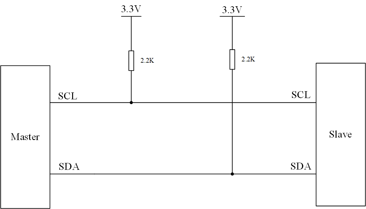
I2C pull-up resistor schematic
Building and Downloading
This sample can be found in the SDK folder:
Project file: board\evb\io_sample\i2c\Self_Test\mdk
Project file: board\evb\io_sample\i2c\Self_Test\gcc
Please follow these steps to build and run the example:
Open sample project file.
To build the target, follow the steps listed on the Generating App Image in Quick Start.
After a successful compilation, the app bin
app_MP_xxx.binwill be generated in the directorymdk\binorgcc\bin.To download app bin into EVB board, follow the steps listed on the MP Tool Download in Quick Start.
Press reset button on EVB board and it will start running.
Experimental Verification
When the I2C_MASTER_SEND_SLAVE_RECEIVE macro is enabled, this example demonstrates the I2C master sending and the slave receiving.
-
When the data received by the Slave reaches the set threshold level, it triggers the
I2C_INT_RX_FULLinterrupt and prints the log.I2C1 Rx Full detected
-
When the Master finishes sending data, the Slave detects the stop signal, both Master and Slave trigger the
I2C_INT_STOP_DETinterrupt and print the log.I2C0 Stop signal detected I2C1 Stop signal detected
-
Within the interrupt function on the Slave, print the length and content of the received data.
Slave Recv Date Lenth = 24
I2C1_Slave_ReceiveData=0
...
I2C1_Slave_ReceiveData=23
When the I2C_MASTER_RECEIVE_SLAVE_SEND macro is enabled, this example demonstrates the I2C master receiving and the slave sending.
-
The Slave receives a read request sent by the Master, triggering the
I2C_INT_RD_REQinterrupt and printing a log.Enter I2C1 interrupt I2C1_INT_RD_REQ!
-
Print the data received by the Master.
Master Read data = 10
...
Master Read data = 33
When the I2C_MASTER_REPEAT_READ macro is enabled, this example demonstrates the I2C master continuously sending and receiving data.
-
The Slave receives a read request from the Master, triggering the
I2C_INT_RD_REQinterrupt, and logs it.Enter I2C1 interrupt I2C1_INT_RD_REQ!
-
The Slave receives data from the Master, prints the length and content of the received data within the Slave's interrupt function.
Slave Recv Date Lenth = 4
I2C1_Slave_ReceiveData=1
I2C1_Slave_ReceiveData=2
I2C1_Slave_ReceiveData=3
I2C1_Slave_ReceiveData=4
-
Slave receives the data and prints a log.
I2C1 RX_DONE detected
-
Slave sends the data back to Master. After Master receives the data, it prints a log.
I2C0 Stop signal detected
-
Print the data received by Master.
Master Repeat Read data = 10
...
Master Repeat Read data = 33
Code Overview
This chapter will be introduced according to the following several parts:
Peripheral initialization will be introduced in chapter Initialization.
Functional implementation after initialization will be introduced in chapter Function Implementation.
Source Code Directory
Project directory:
sdk\board\evb\io_sample\i2c\Self_TestSource code directory:
sdk\src\sample\io_sample\i2c\Self_Test
Source files are currently categorized into several groups as below.
└── Project: self_test
    └── secure_only_app
        └── include
            ├── app_define.h
            └── rom_uuid.h
        ├── cmsis                    includes CMSIS header files and startup files
            ├── overlay_mgr.c
            ├── system_rtl876x.c
            └── startup_rtl876x.s
        ├── lib                      includes all binary symbol files that user application is built on
            ├── rtl8752h_sdk.lib
            ├── gap_utils.lib
            └── ROM.lib
        ├── peripheral               includes all peripheral drivers and module code used by the application
            ├── rtl876x_rcc.c
            ├── rtl876x_pinmux.c
            ├── rtl876x_nvic.c
            └── rtl876x_i2c.c
        ├── profile
        └── app                      includes the ble_peripheral user application implementation
            └── main.c
Initialization
When the EVB reset, the main function is executed, following these steps:
int main(void)
{
    extern uint32_t random_seed_value;
    srand(random_seed_value);
    __enable_irq();
    i2c_demo();

    while (1)
    {
        __NOP();
        __NOP();
        __NOP();
        __NOP();
        __NOP();
        __NOP();
    }
}
In i2c_demo, it includes PAD/PINMUX settings, I2C peripheral initialization, and interrupt configuration initialization.
void i2c_demo(void)
{
    /* Configure pad and pinmux firstly! */
    board_i2c_master_init();
    board_i2c_slave_init();

    /* Initialize i2c peripheral */
    driver_i2c_master_init();
    driver_i2c_slave_init();

    /* Config i2c nvic */
    nvic_i2c_config();

    ...
}
board_i2c_master_init and board_i2c_slave_init are for configuring the PAD/PINMUX settings of I2C0 and I2C1, including the following processes:
Configure PAD: Set pins, PINMUX mode, PowerOn, internal pull-up, output enable, and output high.
Configure PINMUX: Assign pins to I2C0_CLK, I2C0_DAT, I2C1_CLK, and I2C1_DAT functions respectively.
driver_i2c_master_init is for the initialization of the I2C0 peripheral, including the following processes:
Enable the RCC clock source.
Set the I2C clock frequency to 100kHz.
Set the device mode to master mode.
Set the I2C address to 7-bit address mode.
Set the slave address to 0x50.
Enable the ACK function.
Enable I2C0.
void driver_i2c_master_init(void)
{
    /* Initialize I2C peripheral */
    RCC_PeriphClockCmd(APBPeriph_I2C0, APBPeriph_I2C0_CLOCK, ENABLE);

    I2C_InitTypeDef  I2C_InitStruct;
    I2C_StructInit(&I2C_InitStruct);

    I2C_InitStruct.I2C_ClockSpeed       = 100000;
    I2C_InitStruct.I2C_DeviveMode       = I2C_DeviveMode_Master;
    I2C_InitStruct.I2C_AddressMode      = I2C_AddressMode_7BIT;
    I2C_InitStruct.I2C_SlaveAddress     = 0x50;
    I2C_InitStruct.I2C_RxThresholdLevel = 8;
    I2C_InitStruct.I2C_Ack              = I2C_Ack_Enable;

    I2C_Init(I2C0, &I2C_InitStruct);
    I2C_Cmd(I2C0, ENABLE);
}
driver_i2c_slave_init is the initialization for the I2C1 peripheral, which includes the following steps:
Enable the RCC clock.
Set the I2C clock frequency to 100kHz.
Set the device mode to slave mode.
Set the I2C address to 7-bit address mode.
Set the slave address to 0x50.
Enable the ACK function.
Enable I2C1.
void driver_i2c_slave_init(void)
{
    /* Initialize I2C peripheral */
    RCC_PeriphClockCmd(APBPeriph_I2C1, APBPeriph_I2C1_CLOCK, ENABLE);

    I2C_InitTypeDef  I2C_InitStruct;
    I2C_StructInit(&I2C_InitStruct);

    I2C_InitStruct.I2C_ClockSpeed        = 100000;
    I2C_InitStruct.I2C_DeviveMode        = I2C_DeviveMode_Slave;
    I2C_InitStruct.I2C_AddressMode       = I2C_AddressMode_7BIT;
    I2C_InitStruct.I2C_SlaveAddress      = 0x50;
    I2C_InitStruct.I2C_RxThresholdLevel  = 8;
    I2C_InitStruct.I2C_Ack               = I2C_Ack_Enable;

    I2C_Init(I2C1, &I2C_InitStruct);
    I2C_Cmd(I2C1, ENABLE);
}
nvic_i2c_config is for the interrupt configuration under different macro settings, including the following process:
Clear all interrupt pending bits.
If the macro
I2C_MASTER_SEND_SLAVE_RECEIVEis enabled:
Configure the
I2C_INT_STOP_DETinterrupt for the Master.Configure the
I2C_INT_RX_FULL,I2C_INT_STOP_DET, andI2C_INT_RX_DONEinterrupts for the Slave.If the macro
I2C_MASTER_RECEIVE_SLAVE_SENDis enabled, configure theI2C_INT_RD_REQinterrupt for the Slave.If the macro
I2C_MASTER_REPEAT_READis enabled:
Configure the
I2C_INT_STOP_DETinterrupt for the Master.Configure the
I2C_INT_RX_FULL,I2C_INT_STOP_DET,I2C_INT_RX_DONE, andI2C_INT_RD_REQinterrupts for the Slave.void nvic_i2c_config(void) { /* Detect stop signal */ I2C_ClearINTPendingBit(I2C0, I2C_INT_STOP_DET); I2C_ClearINTPendingBit(I2C1, I2C_INT_STOP_DET); /* Detect read require signal */ I2C_ClearINTPendingBit(I2C1, I2C_INT_RD_REQ); /* Detect rx fifo full signal */ I2C_ClearINTPendingBit(I2C1, I2C_INT_RX_FULL); /* Detect rx transmission finished signal */ I2C_ClearINTPendingBit(I2C1, I2C_INT_RX_DONE); #if I2C_MASTER_SEND_SLAVE_RECEIVE I2C_INTConfig(I2C0, I2C_INT_STOP_DET, ENABLE); I2C_INTConfig(I2C1, I2C_INT_RX_FULL, ENABLE); I2C_INTConfig(I2C1, I2C_INT_STOP_DET, ENABLE); I2C_INTConfig(I2C1, I2C_INT_RX_DONE, ENABLE); #endif #if I2C_MASTER_RECEIVE_SLAVE_SEND I2C_INTConfig(I2C1, I2C_INT_RD_REQ, ENABLE); #endif #if I2C_MASTER_REPEAT_READ I2C_INTConfig(I2C0, I2C_INT_STOP_DET, ENABLE); I2C_INTConfig(I2C1, I2C_INT_RX_FULL, ENABLE); I2C_INTConfig(I2C1, I2C_INT_STOP_DET, ENABLE); I2C_INTConfig(I2C1, I2C_INT_RX_DONE, ENABLE); I2C_INTConfig(I2C1, I2C_INT_RD_REQ, ENABLE); #endif /* Config I2C interrupt */ NVIC_InitTypeDef NVIC_InitStruct; NVIC_InitStruct.NVIC_IRQChannel = I2C0_IRQn; NVIC_InitStruct.NVIC_IRQChannelPriority = 3; NVIC_InitStruct.NVIC_IRQChannelCmd = ENABLE; NVIC_Init(&NVIC_InitStruct); NVIC_InitStruct.NVIC_IRQChannel = I2C1_IRQn; NVIC_InitStruct.NVIC_IRQChannelPriority = 3; NVIC_InitStruct.NVIC_IRQChannelCmd = ENABLE; NVIC_Init(&NVIC_InitStruct); }
Functional Implementation
When the I2C_MASTER_SEND_SLAVE_RECEIVE macro is enabled, this example demonstrates the I2C master sending and the slave receiving.
After the initialization stage is completed, execute
I2C_MasterWrite(), the master sends data to the slave, and the slave receives the data sent by the master.-
When the amount of data received by the slave reaches the set threshold, it triggers the
I2C_INT_RX_FULLinterrupt and enters the interrupt handler functionI2C1_Handler.Obtain the length of the received data in the RX FIFO and save the received data.
Record the length of the received data and clear the interrupt flag.
void I2C1_Handler(void)
{
    ...
    if (I2C_GetINTStatus(I2C1, I2C_INT_RX_FULL) == SET)
    {
        DBG_DIRECT("I2C1 Rx Full detected");
        lenth = I2C_GetRxFIFOLen(I2C1);

        /*read I2C data*/
        for (uint32_t i = 0; i < lenth; i++)
        {
            I2C_Rev_Data[I2C_Rev_Index++] = I2C_ReceiveData(I2C1);
        }
        I2C_Rev_Data_Lenth += lenth;

        I2C_ClearINTPendingBit(I2C1, I2C_INT_RX_FULL);
    }

}
-
When the slave receives data and the stop signal is detected, it triggers the
I2C_INT_STOP_DETinterrupt and enters the interrupt handler functionI2C1_Handler.Obtain the length of the received data in the RX FIFO and save the received data.
Record the length of the data received and clear the interrupt flag.
Print all the received data.
void I2C1_Handler(void)
{
    ...
    if (I2C_GetINTStatus(I2C1, I2C_INT_STOP_DET) == SET)
    {
        DBG_DIRECT("I2C1 Stop signal detected");

        /*read I2C receive data*/
        lenth = I2C_GetRxFIFOLen(I2C1);
        for (uint32_t i = 0; i < lenth; i++)
        {

            I2C_Rev_Data[I2C_Rev_Index++] = I2C_ReceiveData(I2C1);
        }
        I2C_Rev_Data_Lenth += lenth;
        I2C_ClearINTPendingBit(I2C1, I2C_INT_STOP_DET);

        DBG_DIRECT("Slave Recv Date Lenth = %d", I2C_Rev_Data_Lenth);

        for (uint32_t i = 0; i < I2C_Rev_Data_Lenth; i++)
        {
            DBG_DIRECT("I2C1_Slave_ReceiveData=%d\n", I2C_Rev_Data[i]);
        }

    }

}
When the I2C_MASTER_RECEIVE_SLAVE_SEND macro is enabled, this example demonstrates the I2C master receiving and the slave sending.
After the initialization phase is completed, execute
I2C_MasterRead()to send a read request command to the Slave and wait to receive data.-
When the Slave detects the read request command, it triggers the
I2C_INT_RD_REQinterrupt and enters the interrupt handler functionI2C1_Handler.Execute the
I2C_SendCmd()command to send data to the Slave.After sending the data, clear the
I2C_INT_RD_REQinterrupt pending bit.
void I2C1_Handler(void)
{
    uint16_t lenth;

    uint8_t send_data_buffer[100];
    for (uint32_t i = 0; i < TransferLength; i++)
    {
        send_data_buffer[i] = i + 10;
    }
    if (I2C_GetINTStatus(I2C1, I2C_INT_RD_REQ) == SET)
    {
        DBG_DIRECT("Enter I2C1 interrupt I2C1_INT_RD_REQ!");

        for (uint32_t i = 0; i < TransferLength; i++)
        {
            I2C_SendCmd(I2C1, I2C_WRITE_CMD, send_data_buffer[i], I2C_STOP_DISABLE);
        }

        I2C_ClearINTPendingBit(I2C1, I2C_INT_RD_REQ);

    }
    ...
}
-
After the Master end has received the complete data, it prints the data.
void i2c_demo(void)
{
    ...
#if I2C_MASTER_RECEIVE_SLAVE_SEND
    /* I2C master read */
    uint8_t data[TransferLength] = {0};
    I2C_MasterRead(I2C0, data, TransferLength);

    for (uint32_t i = 0; i < TransferLength ; i++)
    {
        DBG_DIRECT("Master Read data = %d\n", data[i]);
    }
#endif
    ...
}
When the I2C_MASTER_REPEAT_READ macro is enabled, this example demonstrates the I2C master continuously sending and receiving data.
-
Master executes
I2C_RepeatRead()to send data to the Slave and waits for the Slave to respond with data.void i2c_demo(void) { ... #if I2C_MASTER_REPEAT_READ /* I2C master repeat read */ uint8_t tx_data[10] = {01, 02, 03, 04}; uint8_t rx_data[TransferLength] = {0}; I2C_RepeatRead(I2C0, tx_data, 4, rx_data, TransferLength); for (uint32_t i = 0; i < TransferLength ; i++) { DBG_DIRECT("Master Repeat Read data = %d\n", rx_data[i]); } #endif }
Slave receives the data sent by the Master. When the Slave's receive FIFO is full, it triggers the
I2C_INT_RX_FULLinterrupt, or when a stop signal is detected, it triggers theI2C_INT_STOP_DETinterrupt, receiving the data sent by the Master.When the Slave detects an RD_REQ request, it triggers the
I2C_INT_RD_REQinterrupt and sends data back to the Master.
See Also
Please refer to the relevant API Reference: