Tx Polling
This example implements data transmission using the I2S peripheral in polling mode.
The logic analyzer can be used to observe the waveform of the transmitted data.
Requirements
The sample supports the following development kits:
Hardware Platforms |
Board Name |
|---|---|
RTL8752H HDK |
RTL8752H EVB |
For more requirements, please refer to Quick Start.
Wiring
Connect P3_2 (LRCK), P3_3 (BCLK), and P4_0 (DATA) on the EVB to the logic analyzer.
Building and Downloading
This sample can be found in the SDK folder:
Project file: board\evb\io_sample\I2S\Tx_polling\mdk
Project file: board\evb\io_sample\I2S\Tx_polling\gcc
Please follow these steps to build and run the example:
Open sample project file.
To build the target, follow the steps listed on the Generating App Image in Quick Start.
After a successful compilation, the app bin
app_MP_xxx.binwill be generated in the directorymdk\binorgcc\bin.To download app bin into EVB board, follow the steps listed on the MP Tool Download in Quick Start.
Press reset button on EVB board and it will start running.
Experimental Verification
Observing the I2S output waveform on the logic analyzer. The I2S output waveform is shown as follows.
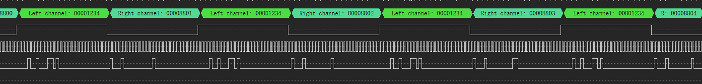
I2S output waveform
Code Overview
This chapter will be introduced according to the following several parts:
Peripheral initialization will be introduced in chapter Initialization.
Functional implementation after initialization will be introduced in chapter Function Implementation.
Source Code Directory
Project directory:
sdk\board\evb\io_sample\I2S\Tx_pollingSource code directory:
sdk\src\sample\io_sample\I2S\Tx_polling
Source files are currently categorized into several groups as below.
└── Project: tx_polling
    └── secure_only_app
        └── include
            ├── app_define.h
            └── rom_uuid.h
        ├── cmsis                    includes CMSIS header files and startup files
            ├── overlay_mgr.c
            ├── system_rtl876x.c
            └── startup_rtl876x.s
        ├── lib                      includes all binary symbol files that user application is built on
            ├── rtl8752h_sdk.lib
            ├── gap_utils.lib
            └── ROM.lib
        ├── peripheral               includes all peripheral drivers and module code used by the application
            ├── rtl876x_rcc.c
            ├── rtl876x_pinmux.c
            ├── rtl876x_nvic.c
            └── rtl876x_i2s.c
        ├── profile
        └── app                      includes the ble_peripheral user application implementation
            └── main.c
Initialization
When the EVB resets, it executes the main function and performs the following process:
int main(void)
{
    extern uint32_t random_seed_value;
    srand(random_seed_value);
    __enable_irq();
    i2s_demo();

    while (1)
    {
        __NOP();
        __NOP();
        __NOP();
        __NOP();
        __NOP();
        __NOP();
    }
}
In i2s_demo, it includes the PAD/PINMUX setup, the initialization of the I2S peripheral.
void i2s_demo(void)
{
    board_i2s_init();
    driver_i2s_init();
    i2s_senddata();
}
board_i2s_init is for PAD and PINMUX configuration, including the following steps:
Configure PAD: set pins, PINMUX mode, PowerOn, internal pull-none.
Configure PINMUX: assign pins to BCLK_SPORT0, LRC_SPORT0, DACDAT_SPORT0 functions.
driver_i2s_init is for initializing the I2S peripheral, including the following steps:
Enable RCC clock.
Set I2S clock source to 40MHz.
Set the Sample rate to 16kHz.
Set I2S to master device mode.
Set I2S to stereo mode.
Set data width and data format.
Disable I2S DMA transfer.
Enable I2S TX mode.
Note
BCLK=I2S_ClockSource*(I2S_BClockNi/I2S_BClockMi)=1024K, LRCK=BCLK/64=16K
void driver_i2s_init(void)
{
    RCC_PeriphClockCmd(APB_I2S, APB_I2S_CLOCK, ENABLE);

    I2S_InitTypeDef I2S_InitStruct;

    I2S_StructInit(&I2S_InitStruct);
    I2S_InitStruct.I2S_ClockSource      = I2S_CLK_40M;
    /* BCLK = 40MHz*(ni/mi),  LRCK = BCLK/64 */
    I2S_InitStruct.I2S_BClockMi         = 0x271;    /* <!LRCK = 16K */
    I2S_InitStruct.I2S_BClockNi         = 0x10;     /* <!BCLK = 1024K */
    I2S_InitStruct.I2S_DeviceMode       = I2S_DeviceMode_Master;
    I2S_InitStruct.I2S_ChannelType      = I2S_Channel_stereo;
    I2S_InitStruct.I2S_DataWidth        = I2S_Width_16Bits;
    I2S_InitStruct.I2S_DataFormat       = I2S_Mode;
    I2S_InitStruct.I2S_DMACmd           = I2S_DMA_DISABLE;
    I2S_Init(I2S_NUM, &I2S_InitStruct);
    I2S_Cmd(I2S_NUM, I2S_MODE_TX, ENABLE);
}
Functional Implementation
Define the data transmission. When the TX FIFO is not full, execute I2S_SendData() to continuously send data. Observe the transmitted data waveform using a logic analyzer.
void i2s_senddata(void)
{
    uint32_t i = 0x12348800;

    while (1)
    {
        if (I2S_GetTxFIFOFreeLen(I2S_NUM))
        {
            /* 16bit format, lower half word send first! */
            I2S_SendData(I2S_NUM, i++);
        }
    }
}
See Also
Please refer to the relevant API Reference: