RTL8777G Dongle Evaluation Board
Overview
The RTL8777G dongle evaluation board provides a hardware environment for user development, including:
5V to 3.3V power module
Antenna module
LED module
Reset key and two independent keys
FT232 for USB to UART
EVB Blocks Distribution
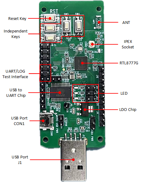
Dongle EVB blocks distribution Diagram (click to enlarge)
The following introduces the main blocks on the evaluation board in counterclockwise order.
Blocks |
Introduction |
|---|---|
Reset Key |
Pressing this key resets the system |
Independent Keys |
SW1, SW2, SW3 and SW4 are connected to P9_1, P9_0, P4_3 and P4_2 respectively |
Supports download mode and normal mode |
|
USB to UART Chip |
FT232RL USB to UART chip for burning program or debugging logs |
Used to power the EVB and connect FT232RL USB to UART chip for burning program or debugging logs |
|
Used to power EVB and communicate with RTL87x2G via USB |
|
LDO Chip |
AMS117-3V3 LDO chip converts a 5V input voltage into a stable 3.3V output voltage |
Provides three LEDs |
|
RTL8777G |
RTL8777G is an ultra-low power wireless microcontroller that supports Bluetooth 5.3/Zigbee/Thread/Master protocols |
Used for external antenna |
|
ANT |
Ceramic antenna |
EVB Interfaces Distribution
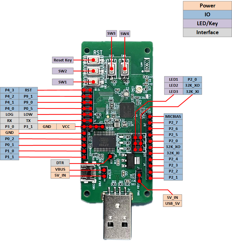
Dongle EVB interfaces distribution Diagram (click to enlarge)
EVB Blocks and Interfaces Introduction
- LED module
LED module can be connected to the pin header within the red box through jumpers, allowing the default GPIO to control the LED. Alternatively, you can use Dupont wires to connect the pin header on the left side of the red box to any GPIO for controlling the LED.
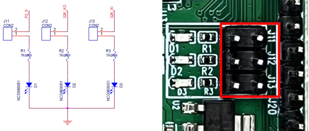
Dongle EVB LED module
- IPEX Socket
The IPEX socket holder is used for external antenna. When using an external antenna, it is necessary to remove capacitor C16 and then place capacitor C33.
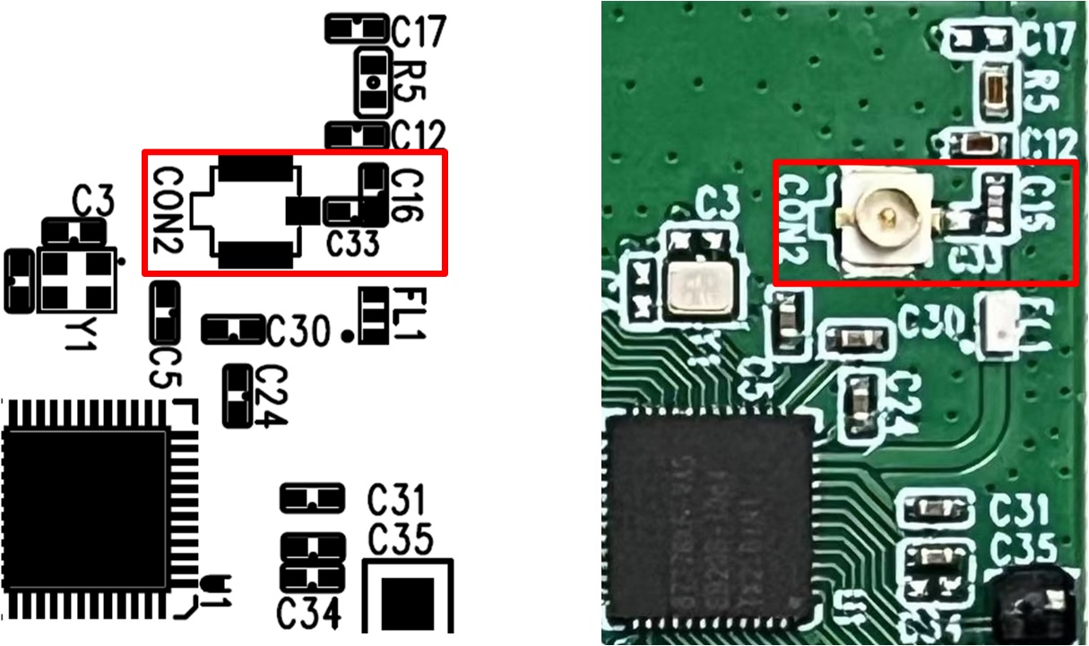
Dongle EVB IPEX Socket
EVB User Guide
EVB Power Connection
The dongle EVB can be powered by USB port CON1 or USB port J1:
Use USB port CON1 for power supply, and connect the jumper marked in red.
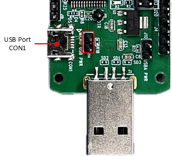
Use USB port CON1 for power supply
Use USB port J1 for power supply, and connect the jumper marked in red.
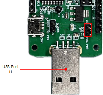
Use USB port J1 for power supply
Download Mode Connection
P0_3 (log) is the download mode selection pin. When P0_3 is pulled low, performing a hardware reset or power cycling will put the system into download mode. Use USB port CON1 for power supply. Use jumpers to connect P3_0 to RX and P3_1 to TX, pull low P0_3. Then power on the board or press the reset button to enter download mode.
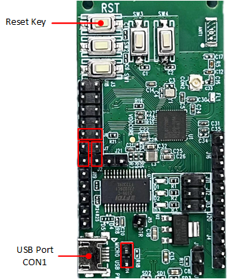
Dongle EVB download mode connection
Normal Mode Connection
Use USB port CON1 for power supply. Connect the jumpers marked in red to connect P0_3 to RX. Then power on the board or press the reset button and start running the program. Log pin can be used for debug.
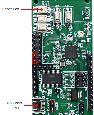
Dongle EVB normal mode connection