Low Power Mode
RTL87x2G supports four power modes.
- CPU ActiveThis mode enables all features for ultimate performance. In Power active mode, if the program does not enter the idle task, the CPU remains in an Active state, and the CPU clock will be in high-speed mode, with a default clock speed of 40MHz.
- CPU SleepIn Power active mode, when system enters into the idle task, the CPU goes into sleep mode, and the CPU clock will automatically slow down. If the CPU is operating at a 40MHz clock, the clock speed will reduce to 625KHz when the CPU is in sleep mode. If a PLL clock is being used, the selection of slow clock depends on the configuration of PLL clock source.
- DLPS (Deep Low Power State)This mode offers proper low power consumption and quick exit and restore time. In DLPS mode, the content of ram is retained.
- Power DownThis mode has extremely low power consumption. However, in power down mode, the content of RAM is not retained. Exiting from Power Down mode requires a reboot process, which takes more time. Only LPC and PAD (without debounce) can wake up the Power Down mode.
Overview
Module usage in different power mode is shown blow. This document will provide detailed information about DLPS mode
Mode |
PAD |
RAM |
Bluetooth |
32K clock |
RTC |
Peripheral |
CPU |
CPU Clock |
|---|---|---|---|---|---|---|---|---|
CPU Active |
√ |
√ |
√ |
√ |
√ |
√ |
√ |
40MHz |
CPU Sleep |
√ |
√ |
√ |
√ |
√ |
√ |
× |
625KHz |
DLPS |
√ |
√ |
× |
√ |
√ |
× |
× |
-- |
PowerPown |
√ |
× |
× |
× |
× |
× |
× |
-- |
Features and Restrictions
The DLPS mode of RTL87x2G has the following features and restrictions:
The system can quickly enter and exit DLPS mode.
Entering DLPS takes less than 1ms
Bluetooth wake-up event: Exiting DLPS takes approximately 4ms
Other wake-up events: Exiting DLPS takes approximately 3ms
The system can be woken up from DLPS by Wakeup Events.
Due to the shutdown of CPU power in DLPS, the SWD function is unavailable, DLPS mode must be disabled during online debugging with J-Link.
Principle
In most cases, the RTL87x2G system can enter an idle state, during which high speed clock, CPU, and peripheral components can be disabled to minimize power consumption as much as possible. However, when an event occurs that requires handling, the system will be woken up from DLPS mode. In this process, the high speed clock, CPU, and Peripherals will be re-powered on and restored to their previous status before entering DLPS mode. After restoration, the system will respond to the wake-up events accordingly. This allows for efficient power management while still being able to handle events when necessary. The processes described above are automatically handled by the system's registered callback functions, so users do not need to worry about them
Enter/Exit from DLPS
Conditions for Entering DLPS Mode
The system can only enter DLPS mode when the following conditions are met simultaneously:
Idle task is running, and all other tasks are either blocked or suspended, with no interrupt service routines (ISRs) occurring.
BT Module checks whether the conditions for entering DLPS are met.
Non-Link mode
State
Description
Standby State
In Standby State, no data is sent or received. BT module will enter sleep mode and no Bluetooth-related event wakes the system up.
Advertising State
(connectable or un-connectable)
if Adv_Interval * 0.625ms >= 15ms, then entering DLPS is permitted, otherwise, it is not permitted.
If Advertising Type is Direct Advertising (High duty cycle), entering DLPS mode is not permitted.
For multi-Advertising , the condition of ‘Adv_Interval * 0.625ms >= 15ms’ also needs to be met.
Scanning State
In Scanning State, if (Scan Interval – Scan Window) * 0.625ms >= 15ms, then entering DLPS mode is permitted; otherwise, it is not permitted.
Link mode (include two roles)
Role
Description
Master Role
In Master Role, when Connection Interval * 1.25ms > 15ms, entering DLPS mode is permitted.
Slave Role
In Slave Role, when Connection Interval * (1+Slave Latency) * 1.25ms > 15ms, entering DLPS mode is permitted.
备注
For multi-link mode, when a device is advertising and a connection has already been created, if the interval between the current time and the next nearest connection or advertising is > 15ms, entering DLPS mode will be permitted.
Platform Module checks whether the conditions for entering DLPS are met.
All the DLPS check callback functions, registered by peripherals and application, return true.
OS SW timer period or task delay period >= 20ms.
备注
If the BT module is allowed to enter DLPS but the platform module is not, the BT module will enter DLPS mode while the platform module remains active.
If the BT module is not allowed to enter DLPS, the system will remain in an active state.
Wakeup Events
The system can be woken up and exit the DLPS mode by one of the following events.
BT Wakeup
- Occurrence of any BT event:
Arrival of an advertising anchor when the BT is in advertising state.
Arrival of a connection event anchor when a BT connection is established.
BT is in scanning state.
Platform Wakeup
PAD wakeup signal
PAD has the function to wake up the system from DLPS mode. Developers can refer to the related hardware manual for more details. Users can use the following API to enable the wakeup function of a pin. When the polarity of a signal on the pin matches the wakeup level, the system will be woken up and then recover from DLPS mode to Active mode.
void System_WakeUpPinEnable(uint8_t Pin_Num, uint8_t Polarity, uint8_t DebounceEn);
If P3_2 is expected to wake up the system from DLPS mode when the signal on the pin becomes a high level, the following configuration should be set as an example.
System_WakeUpPinEnable(P3_2, PAD_WAKEUP_POL_HIGH, PAD_WAKEUP_DEB_DISABLE);
To enable wakeup debounce, you can call the System_WakeUpPinEnable function and set the debounce time to 8ms (default debounce time is 0ms).
System_WakeUpDebounceTime(P3_2, 8);
System_WakeUpPinEnable(P3_2, PAD_WAKEUP_POL_HIGH, PAD_WAKEUP_DEB_ENABLE);
The System handler is a system interrupt that is triggered when System_WakeUpPinEnable enables PAD wake-up, and the current pin state matches the wake-up level. By default, the system disables the system handler after entering DLPS and restores it after exiting DLPS. Therefore, if DLPS is woken up by a pin, the system will enter the system handler interrupt after the system handler is restored.
When debounce wakeup is disabled, the system triggers the system handler after waking up from DLPS. Users can call System_WakeUpInterruptValue in the system handler ISR to query which pin woke up the system. Then, Pad_ClearWakeupINTPendingBit needs to be called to clear the wake-up status of that pin.
uint8_t System_WakeUpInterruptValue(uint8_t Pin_Num);
void Pad_ClearWakeupINTPendingBit(uint8_t Pin_Num);
When debounce wakeup is enabled, the system triggers the system handler after waking up from DLPS. However, the users cannot determine which pin woke up DLPS. They can only call System_WakeupDebounceStatus in the System handler ISR to retrieve the debounce wake-up status. Then, they need to call System_WakeupDebounceClear to clear the debounce wake-up status.
uint8_t System_WakeupDebounceStatus(uint8_t Pin_Num);
void System_WakeupDebounceClear(uint8_t Pin_Num);
When Debounce wake-up is enabled, only if the pin maintains the wake-up level state for a duration longer than the debounce time, DLPS will be woken up, preventing accidental wake-ups. However, the drawback is that after enabling Debounce wake-up, it is not possible to detect which specific pin woke up DLPS.
备注
Although the API related to Debounce includes a pin num parameter, it is mentioned here only to ensure compatibility with different IC series. 87x2G does not support detecting wake-up from different pins under the Debounce wake-up enable. For specific usage examples, please refer to DLPS use sample. For detailed information about the relevant interfaces mentioned above, please refer to :DLPS Mode APIs.
RTC interrupt ( demo project:
samples\io_sample\rtc\rtc_dlps\proj\rtl87x2g\mdk)To enable RTC HW wake up, the following APIs should be called.
RTC_WKConfig(RTC_COMP_WK_INDEX, ENABLE) // enable Comparator wake up
RTC_SystemWakeupConfig(ENABLE);
RTC SW wake up: refer to SW implementation of RTC wake-up.
SW Timer timeout or task delay.
LPC interrupt ( demo project:
samples\io_sample\lpc\voltage_detection_dlps\proj\rtl87x2g\mdk)To enable LPC wake up, the following API needs to be called:
LPC_WKCmd(ENABLE);
AON Q-Decoder interrupt ( demo project:
samples\io_sample\aon_qdec\aon_qdec_dlps\proj\rtl87x2g\mdk)To enable AON Q-Decoder wake up, the following API needs to be called:
AON_QDEC_INITMask(AON_QDEC, AON_QDEC_X_WAKE_AON_MASK, DISABLE);
DLPS Mode Entry Flow
- Prerequisite
If a module needs to be inquired before entering DLPS mode, it should first register a callback function to the Power Manager. When the Power Manager calls the callback function, each module will inform the Power Manager whether or not it should enter DLPS mode based on the return value of the callback function. The BT module is based on the platform module, meaning that the platform module should enter DLPS mode only if the BT module is allowed to enter sleep mode.
- Entry flow
system enters into the idle task
Inquire the BT module whether DLPS mode is allowed to be entered
BT module stores its status and enters DLPS mode.
Inquire the platform module whether DLPS mode is allowed to be entered.
Platform module stores its status and enters DLPS mode.
Send the command to enter DLPS mode.
DLPS Exit Flow
After waking up from DLPS mode, the system first restores power and high speed clock, followed by the recovery of the CPU NVIC and peripherals. Only after the platform module has completely exited DLPS mode, will the system check if other modules need to exit DLPS mode.
- System exitWhen the system exits DLPS mode, it triggers a Reset exception that enters the Reset Handler. In the Reset Handler, the cause of the restart is checked. If it is due to a power-on event, the system follows the restart flow. If it wakes up from DLPS mode, the Platform system follows the DLPS recovery flow to restore power, high speed clock and OS.
- Platform Exit from DLPS completelyThe final stage of platform recovery is completed in the timer task, where the platform completely exits DLPS mode and completes the recovery of the CPU NVIC, peripherals, and the execution of user-defined exit callback functions.
- Checking for the remaining system modules to exit and recover from DLPSChecking if a Bluetooth event has woken up from DLPS. If so, the Bluetooth module exits DLPS and restores its state; otherwise, the Bluetooth module continues to remain in a low-power state.
Hardware Status Storage and Recovery
CPU NVIC
In entering DLPS mode, the CPU is powered off. Therefore, it is necessary to save the NVIC registers before entering DLPS mode and then restore them after exiting from DLPS mode. This process ensures that the interrupt settings are preserved and can be properly restored upon wakeup.
The SDK typically provides default implementations of the CPU_DLPS_Enter and CPU_DLPS_Exit functions to handle this saving and restoring of the NVIC registers. Users do not need to provide implementation details of these functions, as it has been implemented by system.
PAD
The PAD does not power off in DLPS mode. However, to prevent electric leakage and ensure proper operation, certain settings need to be configured for the PAD before entering DLPS. Here are the recommended configurations.
PAD that have not been used or are disabled in the IC should be set as {SW mode, Input mode, Pull Down}. This is the default set of pin, and users don’t need to change.
PAD that have been used should be set as {SW mode, Input mode, Pull Up/Pull Down}. The selection of pull up or pull down depends on the external circuit connected to the pin. If the pin is connected to VDD, it should be pulled up. If it is connected to GND, it should be pulled down.
For PAD with an external circuit voltage between VDD and GND, the pin should be set as {SW mode, Shut down mode, Pull none}. This configuration ensures that the pin is isolated from the external circuit and minimizes power leakage.
PAD that have wake-up ability should be set as {SW mode, Input mode, Pull Up/Pull Down}. The pull mode for a wake-up pin should be set opposite to its wake-up polarity. For example, if a wake-up pin triggers a wake-up event when pulled low, it should be pulled high during DLPS.
It is important to recover the pins to their original settings after exiting DLPS mode. This ensures that the PAD return to their intended functionality and prevent any potential issues.
These pin configurations help maintain proper operation and minimize power consumption during DLPS mode.
Peripherals
Peripherals need to be powered off when entering DLPS (Deep Low Power State), so it is important to save the related settings before entering DLPS and recover them after exiting from DLPS. Before recovering peripheral settings, the peripheral module should be enabled, and the peripheral clock should be started first.
External Sensor
When an external sensor enters or exits from DLPS, processing is performed in two different cases.
If Sensor is not power off, it does not need to be recovered.
If Sensor is powered off, application callback function must be registered, and Sensor will re-initialized in the function.
Storage Flow
The storage of CPU, PINMUX, and peripherals has already been implemented by the system. Since pin settings during entering DLPS can vary depending on the application, the related pin settings are handled in the vendor callback function. This callback function is registered by the application using DLPS_IORegUserDlpsEnterCb. If external sensors are used and need to be handled, the corresponding implementation should also be placed in the same DLPS enter vendor callback.
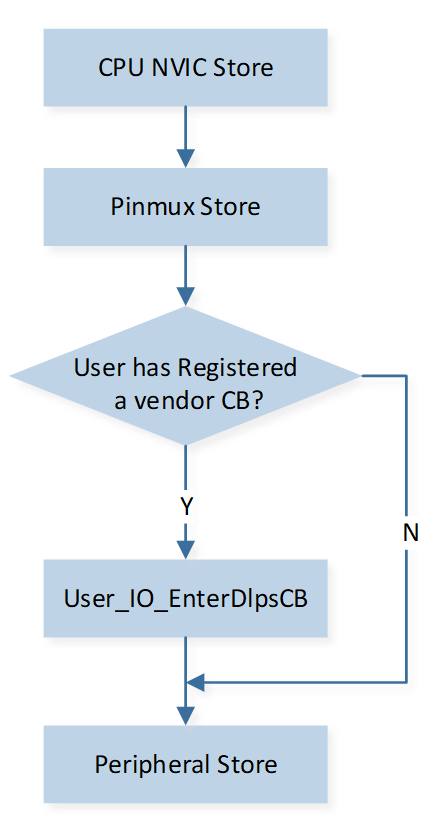
Hardware Store Flow
Recovery Flow
The restoration of CPU, PINMUX, and peripherals has already been implemented by the system. Since pin settings during exiting from DLPS can vary depending on the application, the related pin setting is handled in the callback function. This callback function is registered by the application using DLPS_IORegUserDlpsExitCb. If external sensors are used and need to be handled, the corresponding implementation should also be placed in the same DLPS exit vendor callback.
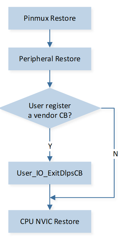
Hardware Restore Flow
Usage of DLPS Settings about Peripherals
Each application has a copy of board.h file, which contains the following DLPS settings for hardware.
/* if use user define DLPS enter/DLPS exit callback function */
#define USE_USER_DEFINE_DLPS_EXIT_CB         1
#define USE_USER_DEFINE_DLPS_ENTER_CB        1

/* if use any peripherals below, #define it  1 */
#define USE_ADC_DLPS                         0
#define USE_GPIOA_DLPS                       0
#define USE_I2C0_DLPS                        0
#define USE_I2C1_DLPS                        0
#define USE_IR_DLPS                          0
#define USE_KEYSCAN_DLPS                     0
#define USE_SPI0_DLPS                        0
#define USE_SPI1_DLPS                        0
#define USE_UART0_DLPS                       0
#define USE_UART1_DLPS                       0
#define USE_ENHTIM_DLPS                      0
If DLPS function of a peripheral needs to be enabled, the corresponding USE_XXX_ DLPS macro should be defined as "1". For some peripherals, such as GDMA, user needs to call the initialization function in the DLPS exit callback function.
If any peripheral is being used, the following API should be called in the application's PwrMgr_Init() function to register the peripheral DLPS function.
DLPS_IORegister();
If any user-defined operations need to be performed during the entering or exiting from DLPS, you should follow the two steps below
Define macro USE_USER_DEFINE_DLPS_EXIT_CB or USE_USER_DEFINE_DLPS_ENTER_CB as ‘1’ in board.h.
Call the following API in application to register and implement callback function.
void DlpsExitCallback(void)
{
    //do something here
}

void DlpsEnterCallback(void)
{
    //do something here
}

DLPS_IORegUserDlpsExitCb(DlpsExitCallback);
DLPS_IORegUserDlpsEnterCb(DlpsEnterCallback);
In the case above, the functions DlpsEnterCallback and DlpsExitCallback will be executed during the entering and exiting from DLPS, respectively. The application can implement specific operations within these functions, such as PAD setting or operations on peripherals.
DLPS use sample
Pad wake up without debounce
Register DLPS check, enter and exit vendor callback function, pull pin P3_2 low to wake up DLPS.
bool DLPS_Check(void)
{
    return true;
}

void EnterDlpsSet(void)  //DLPS Enter
{
    Pad_Config(P3_2, PAD_SW_MODE, PAD_IS_PWRON,
      PAD_PULL_UP, PAD_OUT_DISABLE, PAD_OUT_LOW);
    System_WakeUpPinEnable(P3_2, PAD_WAKEUP_POL_LOW,
      PAD_WAKEUP_DEB_DISABLE);
}

void ExitDlpsInit(void)  //DLPS Exit
{
    Pad_Config(P3_2, PAD_PINMUX_MODE, PAD_IS_PWRON,
      PAD_PULL_UP, PAD_OUT_DISABLE, PAD_OUT_LOW);
}

void pwr_mgr_init(void)
{
#if DLPS_EN
    power_check_cb_register (DLPS_Check);
    DLPS_IORegUserDlpsEnterCb(EnterDlpsSet);  //DLPS Enter CB
    DLPS_IORegUserDlpsExitCb(ExitDlpsInit);  //DLPS Exit CB
    DLPS_IORegister();
    bt_power_mode_set(BTPOWER_DEEP_SLEEP);
    power_mode_set(POWER_DLPS_MODE);
#endif
}
Define System handler to detect which pin wake up DLPS.
void System_Handler(void)
{
    APP_PRINT_INFO0("System_Handler");
    NVIC_DisableIRQ(System_IRQn);

    if (System_WakeUpInterruptValue(P3_2) == SET)
    {
        APP_PRINT_INFO0("P3_2 Wake up");
        Pad_ClearWakeupINTPendingBit(P3_2);
        System_WakeUpPinDisable(P3_2);
    }

    NVIC_ClearPendingIRQ(System_IRQn);
}
Pad wake up with debounce
Register DLPS check, enter and exit vendor callback function, pull pin P3_2 low to wake up DLPS. Set 8ms debounce wake up DLPS.
bool DLPS_Check(void)
{
    return true;
}

void EnterDlpsSet(void)
{
    Pad_Config(P3_2, PAD_SW_MODE, PAD_IS_PWRON,
      PAD_PULL_UP, PAD_OUT_DISABLE, PAD_OUT_LOW);
    System_WakeUpPinDisable(P3_2);
    System_WakeUpDebounceTime(P3_2, 8);
    System_WakeUpPinEnable(P3_2, PAD_WAKEUP_POL_LOW, PAD_WAKEUP_DEB_ENABLE);
}

void ExitDlpsInit(void)
{
    Pad_Config(P3_2, PAD_PINMUX_MODE, PAD_IS_PWRON,
      PAD_PULL_UP, PAD_OUT_DISABLE, PAD_OUT_LOW);
}

void pwr_mgr_init(void)
{
#if DLPS_EN
    power_check_cb_register(DLPS_Check);
    DLPS_IORegUserDlpsEnterCb(EnterDlpsSet);
    DLPS_IORegUserDlpsExitCb(ExitDlpsInit);
    DLPS_IORegister();
    bt_power_mode_set(BTPOWER_DEEP_SLEEP);
    power_mode_set(POWER_DLPS_MODE);
#endif
}
When debounce wake up is used, System handler cannot detect which specific pin wake up DLPS, and can only need to clear debounce status.
void System_Handler(void)
{
    APP_PRINT_INFO0("System_Handler");
    NVIC_DisableIRQ(System_IRQn);

    if(System_WakeupDebounceStatus(P3_2) == SET)
    {
      System_WakeupDebounceClear(P3_2);
        DBG_DIRECT("debounce Wake up");
    }
    NVIC_ClearPendingIRQ(System_IRQn);
}
SW implementation of RTC wake-up
With RTC HW wake up, the system needs to wait until the RTC timeout occurs before exiting DLPS mode. After exiting DLPS mode, the power on and system restore process is executed, and the RTC handler will be called. However, the execution of the RTC handler is delayed by the DLPS exit time.
If higher accuracy in the RTC handler is required, the user can use SW wake up DLPS. After waking up from DLPS, the RTC timeout and handler are executed. By considering the DLPS exit time, the SW wake up DLPS may wake up appropriately in advance, resulting in a more accurate execution time for the RTC handler.
The detailed procedure for using SW wake up DLPS is as follows.
Cancel the call to the RTC wakeup API to disable RTC HW wake up.
Add a next_wakeup_time parameter in the DLPS check callback function and calculate the next wake up time for the RTC timeout in units of 31.25us. In the check callback function, update the next_wakeup_time to the calculated value.
uint32_t RTC_tick; // unit: 32.15us
POWER_CheckResult RTC_Check_GT(uint32_t *next_wakeup_time)  //unit 31.25us
{
    uint32_t wakeup_count = RTC_GetCompValue(RTC_COMP_INDEX) - RTC_GetCounter();
    if(wakeup_count > 0)
    {
        *next_wakeup_time = wakeup_count * RTC_tick;
        return POWER_CHECK_PASS;
    }
    else
    {
        return POWER_CHECK_FAIL;
    }
}
Register DLPS check callback.
RTC_tick = (RTC_PRESCALER_VALUE + 1);
power_check_cb_register(RTC_Check_GT);
DLPS Mode APIs
power_mode_set
Prototype |
int32_t power_mode_set(POWERMode mode) |
|---|---|
Description |
Set Platform power mode |
Parameters |
Power mode: POWERMode enumeration value
|
power_mode_get
Prototype |
POWERMode power_mode_get(void) |
|---|---|
Description |
Get Platform power mode |
Return Value |
Power mode: POWERMode enumeration value
|
bt_power_mode_set
Prototype |
void bt_power_mode_set(BtPowerMode mode) |
|---|---|
Description |
Set BT power mode |
Parameters |
Power mode: BtPowerMode enumeration value
|
bt_power_mode_get
Prototype |
BtPowerMode bt_power_mode_get(void) |
|---|---|
Description |
Get BT power mode |
Return Value |
Power mode: BtPowerMode enumeration value
|
power_mode_pause
Prototype |
int32_t power_mode_pause(void) |
|---|---|
Description |
ctrl stack ++. If ctrl stack > 0, DLPS mode is not allowed to enter |
Parameters |
None |
power_mode_resume
Prototype |
int32_t power_mode_resume(void) |
|---|---|
Description |
ctrl stack --, if ctrl stack is 0, DLPS mode is allowed to enter |
Parameters |
None |
power_get_refuse_reason
Prototype |
uint32_t *power_get_refuse_reason() |
|---|---|
Description |
Get callback function which prevent system to enter into DLPS mode |
Return Value |
Address of callback function |
power_get_wakeup_reason
Prototype |
PowerModeWakeupReason power_get_wakeup_reason() |
|---|---|
Description |
Get wakeup reason when low power mode is exited |
Return Value |
wakeup reason |
power_get_error_code
Prototype |
PowerModeErrorCode power_get_error_code(void) |
|---|---|
Description |
Get error reason which prevent system to enter low power mode |
Return Value |
Error reason |
power_get_statistics
Prototype |
void power_get_statistics(uint32_t *wakeup_count, uint32_t *last_wakeup_clk, uint32_t *last_sleep_clk) |
|---|---|
Description |
Get debug information of DLPS mode |
Parameters |
wakeup_count: total counts of entering and exiting DLPS last wakeup clock: last wakeup time, unit: 31.25us last sleep clock: last sleep time, unit: 31.25us |
power_register_excluded_handle
Prototype |
bool power_register_excluded_handle(void **handle, PowerModeExcludedHandleType type) |
|---|---|
Description |
Exclude SW timer or task from low power wake list, SW timer needs to be one-shot timer |
Parameters |
handle: timer or task handle type: timer or task type |
power_unregister_excluded_handle
Prototype |
bool power_unregister_excluded_handle(void **handle, PowerModeExcludedHandleType type) |
|---|---|
Description |
Cancel exclude timer or task from low power wake list |
Parameters |
handle: timer or task handle type: timer or task type |
power_check_cb_register
Prototype |
int32_t power_check_cb_register(POWERCheckFunc func) |
|---|---|
Description |
Register inquiry callback function to Power Manager. In idle task, system will call this function each time before entering DLPS to decide whether DLPS is allowed to enter. Return value:
|
Parameters |
func: Inquiry callback function |
DLPS_IORegUserDlpsEnterCb
Prototype |
__STATIC_INLINE void DLPS_IORegUserDlpsEnterCb(DLPS_IO_EnterDlpsCB func) |
|---|---|
Description |
This API register user callback for dlps enter stage, which allows custom IO store action by APP |
Parameters |
func: App-specific peripheral storage function |
备注
Do not perform time-consuming operations in the DLPS enter callback, as it may disturb the DLPS wake-up process.
Since the OS schedule and interrupts are disabled during DLPS, it is not recommended to use OS APIs in the DLPS enter callback function.
DLPS_IORegUserDlpsExitCb
Prototype |
__STATIC_INLINE void DLPS_IORegUserDlpsExitCb(DLPS_IO_ExitDlpsCB func) |
|---|---|
Description |
This API register user callback for dlps exit stage, which allows custom IO restore action by APP |
Parameters |
func: App-specific peripheral recovery function |
System_WakeUpPinEnable
Prototype |
void System_WakeUpPinEnable(uint8_t Pin_Num, uint8_t Polarity, uint8_t DebounceEn) |
|---|---|
Description |
This API is used to configure wakeup pin |
Parameters |
|
System_WakeUpDebounceTime
Prototype |
void System_WakeUpDebounceTime(uint8_t time) |
|---|---|
Description |
This API is used to set debounce time |
Parameters |
time: debounce time in ms |
System_WakeUpInterruptValue
Prototype |
uint8_t System_WakeUpInterruptValue(uint8_t Pin_Num) |
|---|---|
Description |
This API is used to query which pin has woken up the system |
Parameters |
Pin_Num: wakeup pin number |