Audio Subsystem
This document provides information about the design philosophy and operating principle of the Audio Subsystem. The Audio Subsystem is an audio-specific domain architecture that standardizes the audio driver abstraction interfaces, virtualizes the audio stream routing mechanism, and provides various high-level modularized components.
Below figure Audio Subsystem Architecture illustrates the architecture of the major elements of the Audio Subsystem. The entire Audio Subsystem is divided by a solid black line: below it is the Audio HAL, and above it is the Audio Framework. The Audio Framework depends on the Audio HAL and is designed to be a platform-independent software component. It can be further divided into the Audio Path, the Audio Core, and high-level function modules. The details of all these components will be disclosed in the following chapters.

Audio Subsystem Architecture
Audio HAL
The Audio HAL defines the standard interfaces of the underlying audio hardware, providing two main benefits:
Easy iteration, updates, or migration of audio hardware devices and platforms, with minimal costs of maintaining the upper Audio Framework.
Constant connection of the lower-level audio hardware modules by the Audio Framework, allowing for independent development.
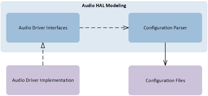
The Audio HAL is composed of driver codes and configurations. Below figure Audio HAL Modeling provides an overview of the Audio HAL and depicts the relations between its interface prototype and implementation.
Audio HAL Modeling
Driver Modeling
Even though each component of the Audio HAL has its own functionalities and defines different API prototypes, they follow the same basic driver modeling policies:
Audio drivers provide simple, thread-unsafe APIs for the upper layers.
Upper layers register driver callbacks to receive driver internal events.
The Audio HAL consists of the following components:
Codec HAL - Provides hardware Codec driver interfaces.
DSP HAL: Provides DSP driver interfaces.
ANC HAL: Provides ambient noise pass-through or cancellation driver interfaces.
PAD HAL: Provides audio pin pad driver interfaces.
Bin Loader HAL: Provides binary file loading interfaces.
Below table Audio HAL Component Location lists the modeling file locations of the Audio HAL components.
HAL Component |
Location |
|---|---|
SPORT |
|
Codec |
|
DSP |
|
ANC |
|
PAD |
|
Bin Loader |
|
SHM |
|
Configuration Files
Audio HAL Configuration Files are considered to be part of the Audio HAL. These files provide Audio driver policies that are not suitable in API style, or too trivial to maintain in API format.
Configuration Files are free to be constructed in any format, e.g. C structure style, XML or INI. They are also free to be declared in raw flash partitions or various file systems.
Note
Currently, we only provide C structure style format declared in raw flash partitions.
Audio Path
The Audio Path is a crucial component in the Audio Subsystem that decouples the entire Audio Framework from the underlying Audio HAL. Its main purpose is to abstract various audio hardware features and group them into different Audio Categories.
The table Audio Category Enumerations below provides a list of Audio Category
enumerations from the file audio_type.h. Each category can be instantiated as one or more Audio
Path instances. In this chapter, we will explain the Path Domain that the
Audio Path modeling is based on, illustrate the Path Lifecycle, and
guide users on customizing the Audio Path with Audio Plugin.
Category |
Description |
|---|---|
AUDIO |
Audio Playback |
VOICE |
Voice Communication |
RECORD |
Record or Capture |
LINE |
Analog or Digital Line-level Loopback |
RINGTONE |
Ringtone |
VP |
Voice Prompt |
APT |
Ambient Pass-through |
LLAPT |
Low-latency Ambient Pass-through |
ANC |
Active Noise Cancellation |
VAD |
Voice Activity Detection |
KWS |
Keyword Spotting |
PIPE |
Coder Conversion pipe |
Path Domain
The Path Domain defines the stream and routing control points for an Audio Path. Each Audio Path is composed of several Audio Path Domains. There are 3 kinds of Audio Path Domains listed in the below table Audio Path Domain Enumerations.
Type |
Description |
|---|---|
Analog |
Analog Control Point |
Digital |
Digital Control Point |
Gateway |
Routing Control Point |
As depicted in the below figure Audio Path Domain, these Path Domains provide the necessary abstraction and resource management capabilities for the underlying drivers, enable the Audio Subsystem to interact with the hardware and perform various audio processing and routing tasks:
Analog Domain serves as the resource manager for the Codec driver and ANC driver. It handles the management and configuration of resources related to analog audio processing, such as Codecs and ANC functionality. It ensures proper control and utilization of analog audio resources.
Digital Domain serves as the resource manager for the DSP driver. It handles the management and configuration of resources related to digital audio processing, such as signal processing algorithms, digital audio effects, and other digital processing capabilities. It allows for the control and customization of digital audio processing functions.
Gateway Domain serves as the resource manager for the SPORT driver. It handles the management and configuration of resources related to audio data transmission and interfacing. This domain ensures proper routing and synchronization of audio data between different devices and interfaces.
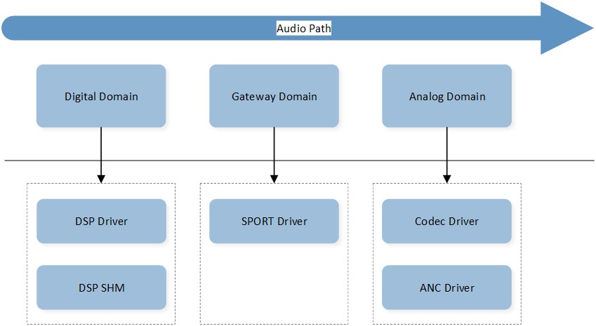
Audio Path Domain
For example, an audio playback path typically routes the stream from the DSP Digital Domain, through the SPORT Gateway Domain, and to the Codec Analog Domain. In contrast, an ANC path only routes the stream within the ANC Analog Domain. There are cases where an Audio Line path may need to route through different Gateways, e.g. AUX IN and SPORT OUT loopback path. To facilitate easy construction of Audio Paths in such scenarios, the Gateway Domain adopts the Factory Method pattern illustrated in the below figure Audio Path Gateway Pattern.
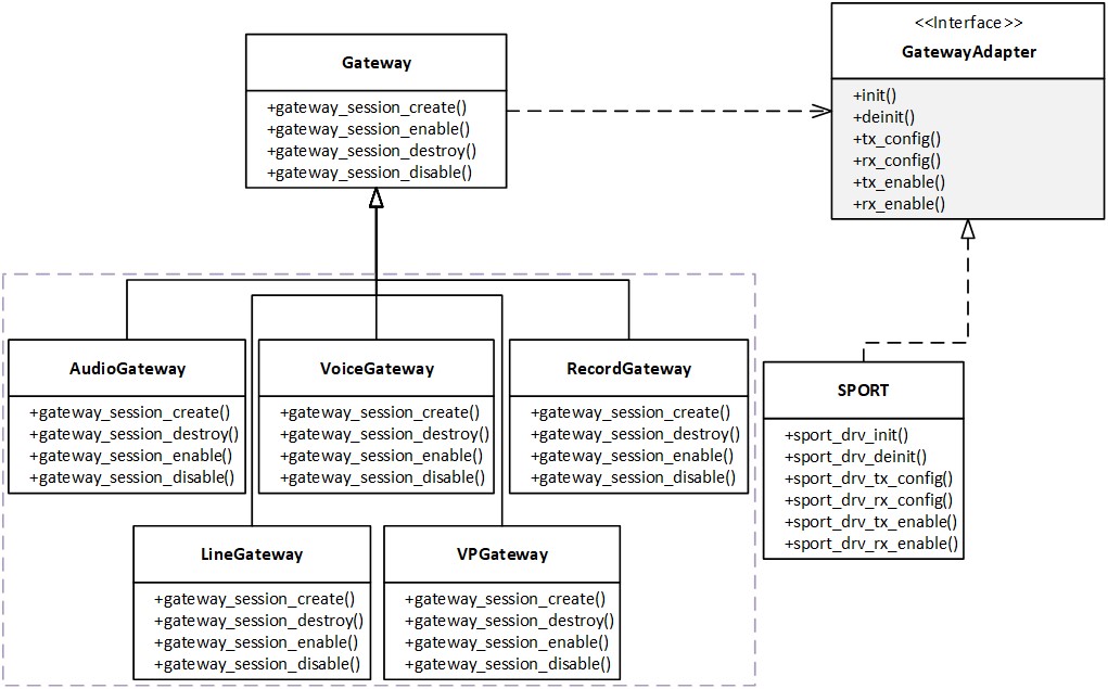
Audio Path Gateway Pattern
Path Lifecycle
As the Audio Path Domain is applied, the Audio Path can unify its external behavior and lifecycle management across different Audio Categories. The lifecycle of an Audio Path Lifecycle can be defined by the following states - Idle, Pending, Ready, Running, Suspending and Stopping. The table Audio Path State Enumerations below provides the definitions for these states.
State |
Description |
|---|---|
Idle |
Path created or stopped. |
Pending |
Path pending for scheduling. |
Ready |
Path pending for starting. |
Running |
Path active and enabled. |
Suspending |
Path under pausing transient state. |
Stopping |
Path under stopping transient state. |
Below figure Audio Path State Machine illustrates the state transitions of an Audio Path. When an Audio Path instance is created, it enters the Idle state. Upon starting the Audio Path, it first transitions to the Pending state which is a transient state for scheduling, and then enters the Ready state for Path Domain enabling. When all Path Domains related to this Audio Path are enabled, it enters the Running state. During the Running state, the Audio Path can be either stopped or paused, transitioning to the Stopping or Suspending state, respectively. Once all Path Domains related to the Audio Path are disabled, it returns to either the Idle state or the Pending state.
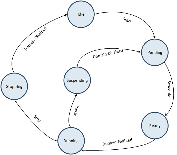
Audio Path State Machine
Note
A paused Audio Path will automatically enter the Pending state for rescheduling. On the other hand, a stopped Audio Path will only be rescheduled if it is started by an upper layer component.
Audio Plugin
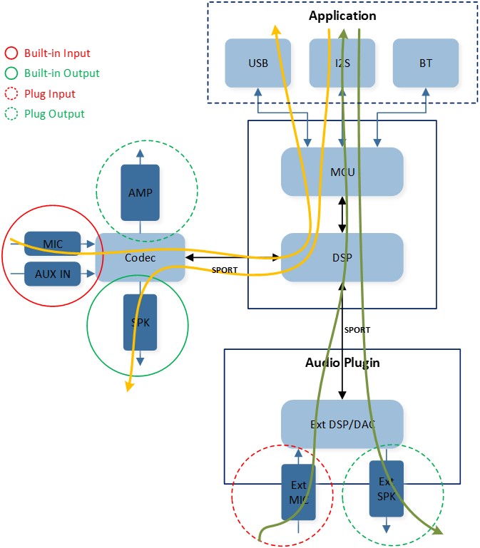
There are certain requirements for customer audio solutions to integrate external audio devices (vendor hardware Codecs, vendor DSPs, DACs, Amplifiers, etc.) into the Audio Subsystem. The Audio Plugin is designed to address these use scenarios, where external audio devices can be seamlessly integrated into Audio Paths and their corresponding stream routings can be customized, without necessitating changes to Audio Paths’ APIs and behaviors.
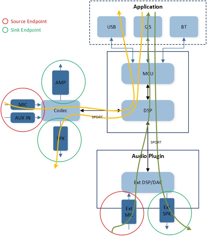
Below figure Audio Plugin Overview provides a high-level overview of the Audio Plugin in the Audio Subsystem. The yellow Line streams represent the default routing configurations:
Uplink stream routes from the builtin input (MIC or Line-in), connected to the internal Codec, through the SPORT Gateway and internal DSP, and finally to the MCU.
Downlink stream routes from the MCU, through the internal DSP and SPORT Gateway, and finally to the builtin output (SPK) connected to the internal Codec.
The green line streams, on the other hand, represent the customized routing configurations:
Uplink stream routes from the plug input (Ext MIC), connected to the Ext DSP, through the SPORT Gateway and internal DSP, and finally to the MCU.
Downlink stream routes from the MCU, through the internal DSP and SPORT Gateway, and finally to the plug output (Ext SPK) connected to the Ext DSP/DAC.
Audio Plugin Overview
Note
Refer to the doc Audio Plugin for detailed guides on using the Audio Plugin.
Audio Route
The Audio Route is used to configure the physical paths that are bound to the corresponding Audio Paths. As mentioned in chapter Audio Path, the Audio Path is responsible for managing hardware resources through Path Domain and providing universal operation interfaces for high layers. The configuration of these hardware resources contained in the Path Domain is done through the Audio Route.
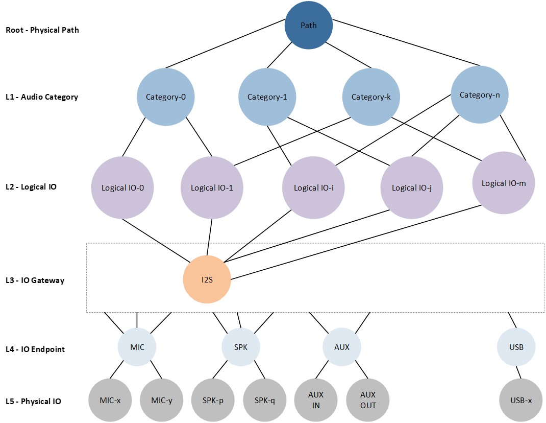
Below figure Audio Route Topology illustrates the topology of the Audio Route. The root node is the Physical Path, with the level-1 Audio Category node representing its specific use scenario. The level-2 Logical IO node indicates the specific routing functionality for the Physical Path. The level-3 IO Gateway node acts as the routing multiplexer for the Physical Path. The level-4 IO Endpoint node indicates the IO type, with the level-5 Physical IO representing its physical identifier. We will introduce these Audio Route terminologies in the following sections.
Audio Route Topology
Physical Path
The Physical Path is the root node (see Audio Route Topology) and the minimum routing granularity of the Audio Route. It defines the hardware layer routing path for the corresponding high layer Audio Path. The Physical Path has the following attributes:
Each Physical Path instance belongs to only one Audio Category.
Each Physical Path instance is composed of Logical IO, IO Gateway, IO Endpoint, and Physical IO.
One or more Physical Path instances of the same Audio Category are grouped together.
Physical Path instances of different Audio Categories likely have different routing control flows.
The routing control flow of each Physical Path instance shall match up with the Audio Path instance to which it is bound.
Logical IO
The Logical IO defines the routing functionality for the Physical Path. Each Physical Path instance shall have one, and only one, Logical IO. Furthermore, all Physical Path instances of the same Audio Category shall have different Logical IOs from each other.
The Logical IO is enumerated in the order of Audio Category as shown in the following table Logical IO Enumerations.
Name |
Value |
Description |
|---|---|---|
Audio Primary Out |
0x00 |
Audio Primary Out |
Audio Secondary Out |
0x01 |
Audio Secondary Out |
Audio Primary Reference Out |
0x02 |
Audio Primary Reference Out |
Audio Secondary Reference Out |
0x03 |
Audio Secondary Reference Out |
Voice Primary Out |
0x10 |
Voice Primary Out |
Voice Secondary Out |
0x11 |
Voice Secondary Out |
Voice Primary Reference Out |
0x12 |
Voice Primary Reference Out |
Voice Secondary Reference Out |
0x13 |
Voice Secondary Reference Out |
Voice Primary Reference In |
0x14 |
Voice Primary Reference In |
Voice Secondary Reference In |
0x15 |
Voice Secondary Reference In |
Voice Primary In |
0x16 |
Voice Primary In |
Voice Secondary In |
0x17 |
Voice Secondary In |
Voice Fusion In |
0x18 |
Voice Fusion In |
Voice Bone Conduction In |
0x19 |
Voice Bone Conduction Sensor In |
Record Primary Reference In |
0x20 |
Record Primary Reference In |
Record Secondary Reference In |
0x21 |
Record Secondary Reference In |
Record Primary In |
0x22 |
Record Primary In |
Record Secondary In |
0x23 |
Record Secondary In |
Record Fusion In |
0x24 |
Record Fusion In |
Record Bone Conduction In |
0x25 |
Record Bone Conduction Sensor In |
Line Primary Out |
0x30 |
Line Primary Out |
Line Secondary Out |
0x31 |
Line Secondary Out |
Line Primary Reference Out |
0x32 |
Line Primary Reference Out |
Line Secondary Reference Out |
0x33 |
Line Secondary Reference Out |
Line Primary Reference In |
0x34 |
Line Primary Reference In |
Line Secondary Reference In |
0x35 |
Line Secondary Reference In |
Line Left In |
0x36 |
Line Left In |
Line Right In |
0x37 |
Line Right In |
Ringtone Primary Out |
0x40 |
Ringtone Primary Out |
Ringtone Secondary Out |
0x41 |
Ringtone Secondary Out |
Ringtone Primary Reference Out |
0x42 |
Ringtone Primary Reference Out |
Ringtone Secondary Reference Out |
0x43 |
Ringtone Secondary Reference Out |
Voice Prompt Primary Out |
0x50 |
Voice Prompt Primary Out |
Voice Prompt Secondary Out |
0x51 |
Voice Prompt Secondary Out |
Voice Prompt Primary Reference Out |
0x52 |
Voice Prompt Primary Reference Out |
Voice Prompt Secondary Reference Out |
0x53 |
Voice Prompt Secondary Reference Out |
APT Primary Out |
0x60 |
APT Primary Out |
APT Secondary Out |
0x61 |
APT Secondary Out |
APT Primary Reference Out |
0x62 |
APT Primary Reference Out |
APT Secondary Reference Out |
0x63 |
APT Secondary Reference Out |
APT Primary Reference In |
0x64 |
APT Primary Reference In |
APT Secondary Reference In |
0x65 |
APT Secondary Reference In |
APT Primary Left In |
0x66 |
APT Primary Left In |
APT Primary Right In |
0x67 |
APT Primary Right In |
APT Secondary Left In |
0x68 |
APT Secondary Left In |
APT Secondary Right In |
0x69 |
APT Secondary Right In |
LL-APT Primary Out |
0x70 |
Low Latency APT Primary Out |
LL-APT Secondary Out |
0x71 |
Low Latency APT Secondary Out |
LL-APT Primary Reference Out |
0x72 |
Low Latency APT Primary Reference Out |
LL-APT Secondary Reference Out |
0x73 |
Low Latency APT Secondary Reference Out |
LL-APT Primary Reference In |
0x74 |
Low Latency APT Primary Reference In |
LL-APT Secondary Reference In |
0x75 |
Low Latency APT Secondary Reference In |
LL-APT Left In |
0x76 |
Low Latency APT Left In |
LL-APT Right In |
0x77 |
Low Latency APT Right In |
ANC Primary Out |
0x80 |
ANC Primary Out |
ANC Secondary Out |
0x81 |
ANC Secondary Out |
ANC Primary Reference Out |
0x82 |
ANC Primary Reference Out |
ANC Secondary Reference Out |
0x83 |
ANC Secondary Reference Out |
ANC Primary Reference In |
0x84 |
ANC Primary Reference In |
ANC Secondary Reference In |
0x85 |
ANC Secondary Reference In |
ANC FF Left In |
0x86 |
ANC Feedforward Left In |
ANC FF Right In |
0x87 |
ANC Feedforward Right In |
ANC FB Left In |
0x88 |
ANC Feedback Left In |
ANC FB Right In |
0x89 |
ANC Feedback Right In |
VAD Primary Reference In |
0x90 |
VAD Primary Reference In |
VAD Secondary Reference In |
0x91 |
VAD Secondary Reference In |
VAD Primary In |
0x92 |
VAD Primary In |
VAD Secondary In |
0x93 |
VAD Secondary In |
IO Gateway
The IO Gateway acts as a multiplexer for the Physical Path and controls its inflow and outflow. It provides common configurations for the Physical Path, such as sample rate, data length, channel length, channel mode, etc.
Currently, the Audio Route supports three Gateway types as defined in the below table IO Gateway Types.
Name |
Value |
|---|---|
I2S |
0x00 |
Each IO Gateway shall have two directions as defined in the below table IO Gateway Directions.
Name |
Value |
|---|---|
Gateway TX |
0x00 |
Gateway RX |
0x01 |
Moreover, each IO Gateway shall support a maximum of 8 Gateway Channels in each direction as specified in the below table IO Gateway Channels.
Name |
Value |
|---|---|
Gateway Channel 0 |
0x00 |
Gateway Channel 1 |
0x01 |
Gateway Channel 2 |
0x02 |
Gateway Channel 3 |
0x03 |
Gateway Channel 4 |
0x04 |
Gateway Channel 5 |
0x05 |
Gateway Channel 6 |
0x06 |
Gateway Channel 7 |
0x07 |
Additionally, each IO Gateway Channel shall have two signal polarities as defined in the below table IO Gateway Channel Polarities.
Name |
Value |
|---|---|
Gateway Channel Positive |
0x00 |
Gateway Channel Negative |
0x01 |
Note
Usually, Gateways are integrated into the Audio Route and controlled by the Audio Subsystem. However, in customized audio solutions, there may be user requirements for Gateways to be controlled directly by applications.
There is a restriction that Gateways can only be controlled exclusively by the Audio Route or Applications. If a specific Gateway is already configured in Tool Configurations, the application shall not control it anymore, and vice versa.
Currently, we only support the I2S Gateway to be controlled by applications. Refer to the doc IO for the usage of I2S at the application layer.
IO Endpoint
The IO Endpoint defines the peripheral interface type for the Physical Paths. It is paired with the Logical IO to distinguish all routing paths from each other.
The IO Endpoint is enumerated as follows in the below table IO Endpoint Enumerations:
Name |
Value |
Description |
|---|---|---|
MIC |
0x00 |
Microphone input endpoint. |
SPK |
0x01 |
Speaker output endpoint. |
AUX |
0x02 |
Auxiliary input endpoint or Auxiliary output endpoint. |
Physical IO
The Physical IO defines the enumerations for the hardware driver layer interface corresponding to each IO Endpoint. Apparently, the Physical IO enumerations of each IO endpoint type are coupled with the underlying hardware capabilities.
The table Physical MIC Enumerations below defines the Physical MIC enumerations of the MIC Endpoint:
Name |
Value |
Description |
|---|---|---|
AUDIO_ROUTE_MIC1 |
0x00 |
Physical microphone 1. |
AUDIO_ROUTE_MIC2 |
0x01 |
Physical microphone 2. |
AUDIO_ROUTE_MIC3 |
0x02 |
Physical microphone 3. |
AUDIO_ROUTE_MIC4 |
0x03 |
Physical microphone 4. |
AUDIO_ROUTE_REF_MIC |
0x0E |
Internal microphone for reference signal in. |
AUDIO_ROUTE_EXT_MIC |
0x0F |
External microphone. |
The table Physical SPK Enumerations below defines the Physical SPK enumerations of the SPK Endpoint:
Name |
Value |
Description |
|---|---|---|
AUDIO_ROUTE_SPK1 |
0x00 |
Physical speaker 1. |
AUDIO_ROUTE_SPK2 |
0x01 |
Physical speaker 2. |
AUDIO_ROUTE_REF_SPK |
0x06 |
Internal speaker for reference signal out. |
AUDIO_ROUTE_EXT_SPK |
0x07 |
External speaker. |
The table Physical AUX Enumerations below defines the Physical AUX enumerations of the AUX Endpoint:
Name |
Value |
Description |
|---|---|---|
AUDIO_ROUTE_AUX_L |
0x00 |
AUX IN left channel. |
AUDIO_ROUTE_AUX_R |
0x01 |
AUX IN right channel. |
Configurations
The Audio Route provides two methods for configuring and controlling the physical paths depicted in figure Audio Route Topology:
API Configurations - Applications can set, update and extend Audio Route configurations at runtime by invoking Audio Route APIs.
Tool Configurations - Users can statically configure the Audio Route using the MCUConfig Tool.
Note
These two configuration methods can be combined, where configurations can be initially set from the MCUConfig Tool and dynamic configurations can be applied at runtime through API invocation if needed.
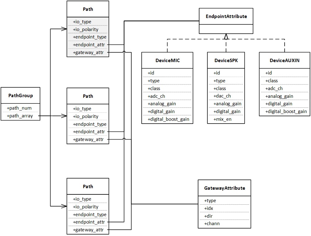
Regardless of the configuration methods chosen, it is important to understand the internal software design and construction ideas illustrated in the below figure Audio Route Construction:
The physical paths of each Audio Category are grouped in a PathGroup, which consists of
path_numandpath_array.path_numindicates the number of physical paths for the specific Audio Category, whilepath_arrayallocates the resources for these physical paths based on the size ofpath_num.Each physical path is represented as a Path, which contains
io_type,io_polarity,endpoint_type,endpoint_attr, andgateway_attr.io_typerepresents the Logical IO;io_polarityis defined in IO Gateway Channel Polarities;endpoint_typerepresents the IO Endpoint;endpoint_attris illustrated in the EndpointAttribute;gateway_attris illustrated in the GatewayAttribute.The EndpointAttribute is a union for Physical IOs. These physical IOs for each Endpoint Type are defined in DeviceMIC, DeviceSPK, and DeviceAUXIN, respectively.
The GatewayAttribute defines the detail attributes for the binding physical path.
Audio Route Construction
API Configurations
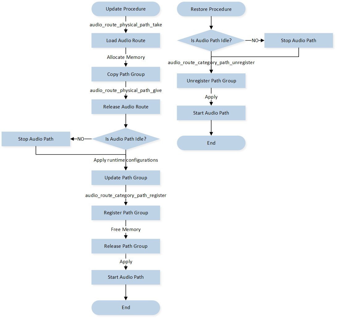
The process of controlling the Audio Route using APIs at runtime is depicted in the below figure Audio Route API Control Flow. Applications should follow the control flow outlined below:
Applications load the Audio Route path group by invoking the
audio_route_physical_path_take()API.Applications should allocate a block of memory to copy the loaded Audio Route path group.
Applications release the Audio Route path group by invoking the
audio_route_physical_path_give()API.Applications can update any fields or attributes as illustrated in figure Audio Route Construction.
Applications register the modified Audio Route path group into the Audio Route component by invoking the
audio_route_category_path_register()API.Applications can unregister and restore the default Audio Route path group if needed by invoking the
audio_route_category_path_unregister()API.
Audio Route API Control Flow
Note
The corresponding Audio Path shall enter the Idle state (see figure Audio Path State Machine) before applications register or unregister the Audio Route path group.
Tool Configurations
Users can statically configure the Audio Route using the MCUConfig Tool. Here are two steps for usage:
Read the doc Audio Route to gain a deeper understanding of Audio Route configurations.
Read the section MCUConfig Tool in the doc Tool Set to learn how to use the MCUConfig Tool.
Audio Stream
The Audio Stream component offers a collection of abstract, efficient, and flexible audio data control and processing functions for the application layer. These functions can be categorized into the following three categories:
Audio Track - Used for handling playback, voice communication, and record streams.
Audio Line - Used to control various loopback streams.
Audio Pipe - Used for codec conversion of various streams.
By utilizing the Audio Route to configure the underlying hardware stream routing paths, developers can conveniently handle complex audio scenarios using the APIs provided by these high-level Audio Stream models. The remainder of this chapter will delve into the implementation details of Audio Track, Audio Line, and Audio Pipe.
Audio Track
The Audio Track provides a set of dedicated high-level APIs for handling playback, voice communication, and record streams. The Playback stream refers to music or multimedia audio. The Voice communication stream refers to various bidirectional speeches transmitted through VoIP, cellular calls, and other mediums. The Record stream is used for speech recognition or data capturing. These three type streams are defined in the table Audio Track Stream Types below:
Type |
Value |
|---|---|
AUDIO_STREAM_TYPE_PLAYBACK |
0x00 |
AUDIO_STREAM_TYPE_VOICE |
0x01 |
AUDIO_STREAM_TYPE_RECORD |
0x02 |
Below figure Audio Track Overview illustrates an overview of the Audio Track across different modules. A playback Audio Track transfers the dedicated stream from the Application layer to the local output Peripherals. A record Audio Track transfers the dedicated stream from the local input Peripherals to the Application layer. A voice Audio Track functions as a combination of the playback Audio Track and the record Audio Track, but with a different stream type.
Audio Track Overview
The table Audio Track Endpoints below summarizes the Audio Track Endpoints for different stream types. Applications shall select the appropriate stream type to create an Audio Track instance.
Type |
Source Endpoint |
Sink Endpoint |
|---|---|---|
AUDIO_STREAM_TYPE_PLAYBACK |
Application |
Output Peripherals |
AUDIO_STREAM_TYPE_VOICE |
Application (Decoder) Input Peripherals (Encoder) |
Output Peripherals (Decoder) Application (Decoder) |
AUDIO_STREAM_TYPE_RECORD |
Input Peripherals |
Application |
Track Modeling
The Audio Track is designed to be based on the Audio Path component and bundled with a Media Buffer instance. As shown in the below figure Audio Track Modeling, the Audio Track utilizes the Audio Path to configure and control the underlying hardware routings, ensuring synchronization between the state of the Audio Track and the Audio Path. Additionally, the Audio Track creates a Media Buffer instance for each stream direction. The Media Buffer instance is responsible for storing stream data for decoding and encoding purposes and provides a set of jitter handling operations for the Audio Track.
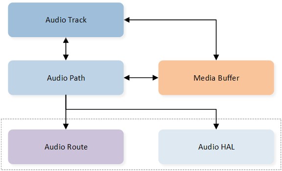
Audio Track Modeling
Track Lifecycle
Each instance of Audio Track has its own lifecycle, which can be defined by the following states: Released, Creating, Created, Starting, Started, Stopping, Stopped, Pausing, Paused, Restarting and Releasing. The definitions of these states are provided in the below table Audio Track State Enumerations.
State |
Description |
|---|---|
Released |
Track instance not existed or destroyed already. |
Creating |
Track instance under creating transient state. |
Created |
Track instance created and statical resources allocated. |
Starting |
Track instance under starting transient state. |
Started |
Track instance started and underlying hardware enabled. |
Stopping |
Track instance under stopping transient state. |
Stopped |
Track instance stopped and underlying hardware disabled. |
Pausing |
Track instance under pausing transient state. |
Paused |
Track instance paused and underlying hardware disabled. |
Restarting |
Track instance under restarting transient state. |
Releasing |
Track instance under releasing transient state. |
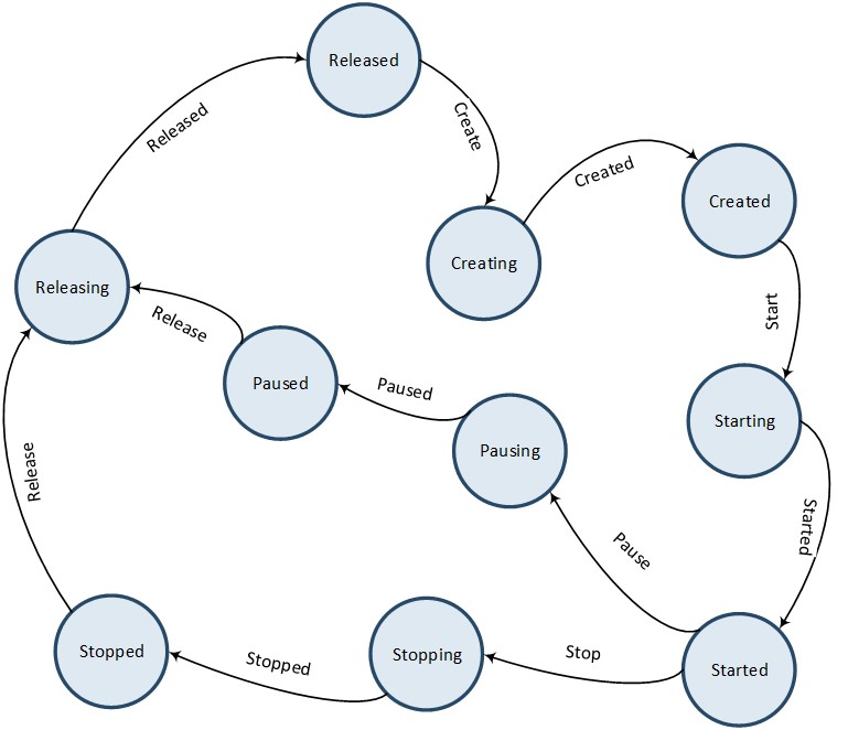
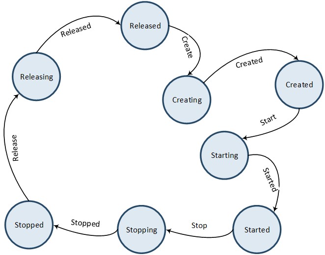
Below figure Audio Track Lifecycle illustrates the state transitions for an Audio Track. When an instance of Audio Track is created, it initially enters the Released state as a temporary placeholder and then transitions directly to the Creating state. Once the creation process of the Audio Track instance is completed, it enters the Created state. From the Created state, the Audio Track instance can either be released directly, transitioning from the Releasing state to the Released state, or it can be started on demand, transitioning from the Starting state to the Started state. An active instance of Audio Track can also be stopped on demand, transitioning from the Stopping state to the Stopped state.
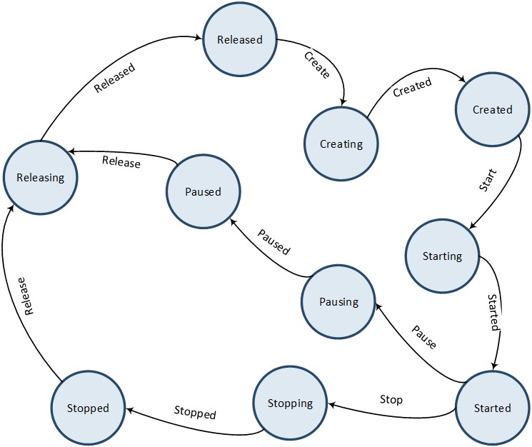
Audio Track Lifecycle
Note
The pause action terminates the Audio Track until the stream in the binding Media Buffer is drained. On the other hand, the stop action terminates the Audio Track directly.
The restart action combines the stop and start actions. If the Audio Track is active, it transitions from the Stopping state to the Stopped state, and then from the Starting to the Started state. If the Audio Track is already stopped or has not been started yet, it will be started directly, transitioning from the Starting state to the Started state.
Audio Line
The Audio Line provides a set of dedicated high-level APIs for stream loopback. The key distinction between the Audio Line and the Audio Track is that the Audio Line stream bypasses the application layer and performs direct underlying stream loopback.
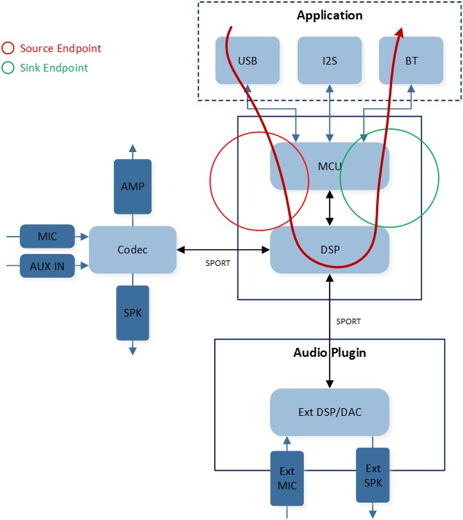
The figure Audio Line Overview below provides an overview of how the Audio Line operates across different modules. Each instance of Audio Line takes the dedicated stream from local input Peripherals and pours it into local output Peripherals. The local input Peripheral can include built-in MIC, external MIC, or AUX IN, while the local output Peripheral can include built-in SPK, external SPK, or AUX Out. The Audio Line supports flexible combinations of the input and output Peripherals.
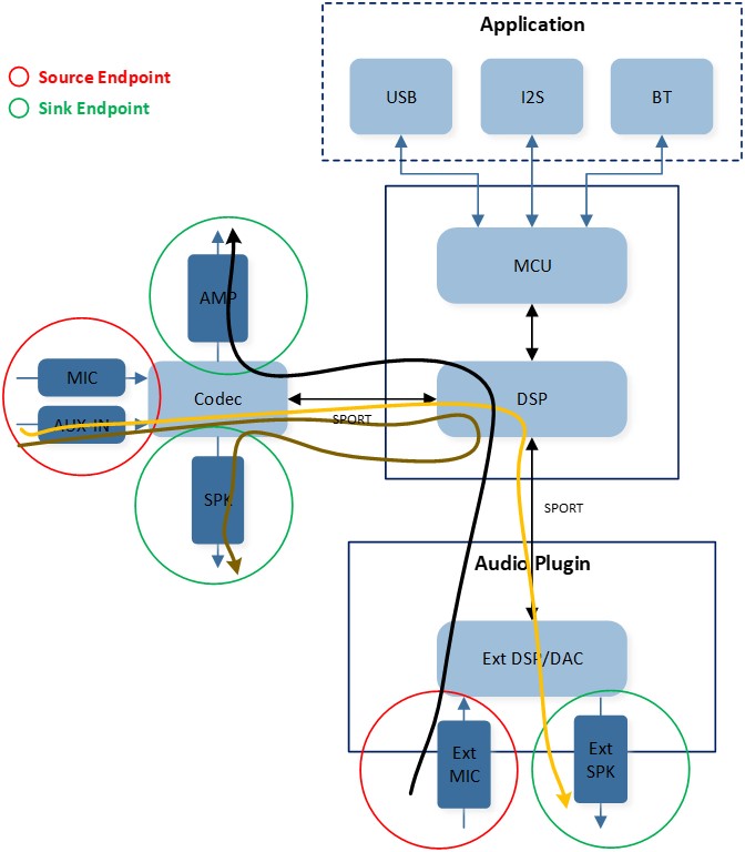
Audio Line Overview
Line Modeling
The Audio Line is designed to be based on the Audio Path component. As shown in the below figure Audio Line Modeling, the Audio Line utilizes the capabilities of the Audio Path component to configure and control the hardware routing. As a result, the state of the Audio Line is synchronized with the state of the Audio Path component.
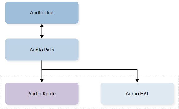
Audio Line Modeling
Line Lifecycle
Each instance of Audio Line follows a specific lifecycle defined by the following states: Released, Creating, Created, Starting, Started, Stopping, Stopped, Pausing, Paused, and Releasing. The definitions of these states are provided in the below table Audio Line State Enumerations.
State |
Description |
|---|---|
Released |
Line instance not existed or destroyed already. |
Creating |
Line instance under creating transient state. |
Created |
Line instance created and statical resources allocated. |
Starting |
Line instance under starting transient state. |
Started |
Line instance started and underlying hardware enabled. |
Stopping |
Line instance under stopping transient state. |
Stopped |
Line instance stopped and underlying hardware disabled. |
Pausing |
Line instance under pausing transient state. |
Paused |
Line instance paused and underlying hardware disabled. |
Releasing |
Line instance under releasing transient state. |
The figure Audio Line Lifecycle below illustrates the state transitions of an Audio Line instance. When an Audio Line instance is created, it initially enters the Released state as a temporary placeholder. It then transitions directly to the Creating state. Once the creation process is completed, the instance enters the Created state. From the Created state, an Audio Line instance can be released directly by transitioning from the Releasing state to the Released state, or it can be started on demand by transitioning from the Starting state to the Started state. An active Audio Line instance can be stopped on demand by transitioning from the Stopping state to the Stopped state.
Audio Line Lifecycle
Note
Refer to the doc Audio Line for detailed guides on using the Audio Line.
Audio Pipe
The Audio Pipe provides a set of dedicated high-level APIs for codec conversion. The figure Audio Pipe Overview below illustrates an overview of how the Audio Pipe operates across different modules. Each Audio Pipe instance retrieves the dedicated stream from the Application layer, converts the stream’s codec format, and then returns the converted stream to the Application layer.
Audio Pipe Overview
The table Codec Type Enumerations below lists the codec types supported by the Audio Pipe. The Audio Pipe not only facilitates the conversion between different codec types but also enables the conversion of specific codec attributes within the same codec type.
Type |
Value |
|---|---|
AUDIO_FORMAT_TYPE_PCM |
0x00 |
AUDIO_FORMAT_TYPE_CVSD |
0x01 |
AUDIO_FORMAT_TYPE_MSBC |
0x02 |
AUDIO_FORMAT_TYPE_SBC |
0x03 |
AUDIO_FORMAT_TYPE_AAC |
0x04 |
AUDIO_FORMAT_TYPE_OPUS |
0x05 |
AUDIO_FORMAT_TYPE_FLAC |
0x06 |
AUDIO_FORMAT_TYPE_MP3 |
0x07 |
AUDIO_FORMAT_TYPE_LC3 |
0x08 |
AUDIO_FORMAT_TYPE_LDAC |
0x09 |
AUDIO_FORMAT_TYPE_LHDC |
0x0A |
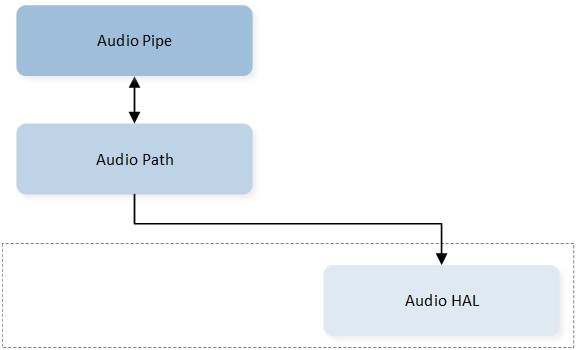
Pipe Modeling
The Audio Pipe is designed to be based on the Audio Path component. As shown in the below figure Audio Pipe Modeling, the Audio Pipe utilizes the capabilities of the Audio Path component to configure and control the hardware routing. Therefore, the state of the Audio Pipe is synchronized with the state of the Audio Path.
Audio Pipe Modeling
Note
The Audio Pipe only controls Audio Path’s Digital Domain, so the Audio Route is not included in the Audio Pipe’s control.
Pipe Lifecycle
Each instance of Audio Pipe follows a specific lifecycle defined by the following states: Released, Creating, Created, Starting, Started, Stopping, Stopped, and Releasing. The definitions of these states are provided in the below table Audio Pipe State Enumerations.
State |
Description |
|---|---|
Released |
Pipe instance not existed or destroyed already. |
Creating |
Pipe instance under creating transient state. |
Created |
Pipe instance created and statical resources allocated. |
Starting |
Pipe instance under starting transient state. |
Started |
Pipe instance started and underlying hardware enabled. |
Stopping |
Pipe instance under stopping transient state. |
Stopped |
Pipe instance stopped and underlying hardware disabled. |
Releasing |
Pipe instance under releasing transient state. |
The figure Audio Pipe Lifecycle below illustrates the state transitions of an Audio Pipe instance. When an Audio Pipe instance is created, it initially enters the Released state as a temporary placeholder. It then transitions directly to the Creating state. Once the creation process is completed, the instance enters the Created state. From the Created state, an Audio Pipe instance can be released directly by transitioning from the Releasing state to the Released state, or it can be started on demand by transitioning from the Starting state to the Started state. An active Audio Pipe instance can be stopped on demand by transitioning from the Stopping state to the Stopped state.
Audio Pipe Lifecycle
Note
Refer to the doc Audio Pipe for detailed guides on using the Audio Pipe.
Notification
Notifications are audio messages that are short and urgent for users. Currently, the Audio Subsystem supports three types of notifications:
Ringtone: Generated by the Frequency Modulation (FM) synthesizer.
Voice Prompt: Pre-recorded voice interaction data.
TTS: Speech generated by the speech synthesizer.
The Notification module within the Audio Subsystem operates asynchronously. An application can trigger multiple notification instances, which may have the same or different notification types. As shown in the below figure Notification Architecture, the application invokes Notification APIs to play, stop, cancel, or flush notifications. These activities are then serialized into a queue by the Notification Activity Manager. The Notification Scheduler receives requests from the Notification Activity Manager and controls the lifecycle of Notification instances by performing the following tasks:
Manipulating the Notification Buffers attached to Notification instances.
Manipulating the Audio Paths attached to Notification instances.
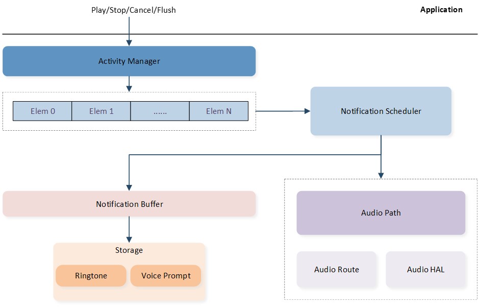
Notification Architecture
Ringtone
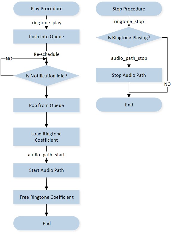
A Ringtone is a sine-wave synthesized sound used for notifications, alarms, prompts, or other situations. The APIs used to control the Ringtone are illustrated in the below figure Ringtone Control Flow. The Application should follow the control flow outlined below:
The Application invokes the
ringtone_play()API to trigger the start procedure.The Notification module pushes this Ringtone activity into the queue.
If the Notification module is busy, the activity is pended for rescheduling. Otherwise, the activity is popped from the queue.
The specific Ringtone coefficients are loaded from storage.
The Ringtone Audio Path is started, and the loaded Ringtone coefficients are freed.
The Application can stop the playing Ringtone by invoking the
ringtone_stop()API.
Ringtone Control Flow
Voice Prompt
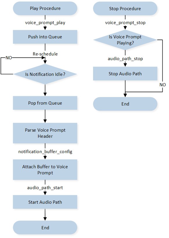
A Voice Prompt is used to play voice files in the required languages. It is used for notifications, alarms, user confirmations, and other situations that require voice prompts. The APIs used to control the Voice Prompt are illustrated in the below figure Voice Prompt Control Flow. The Application should follow the control flow outlined below:
The Application invokes the
voice_prompt_play()API to trigger the start procedure.The Notification module pushes this Voice Prompt activity into the queue.
If the Notification module is busy, the activity is pended for rescheduling. Otherwise, the activity is popped from the queue.
The specific Voice Prompt header is parsed from storage.
The Notification Buffer is attached to the Voice Prompt instance.
The Voice Prompt Audio Path is started.
The Application can stop the playing Voice Prompt by invoking the
voice_prompt_stop()API.
Voice Prompt Control Flow
TTS
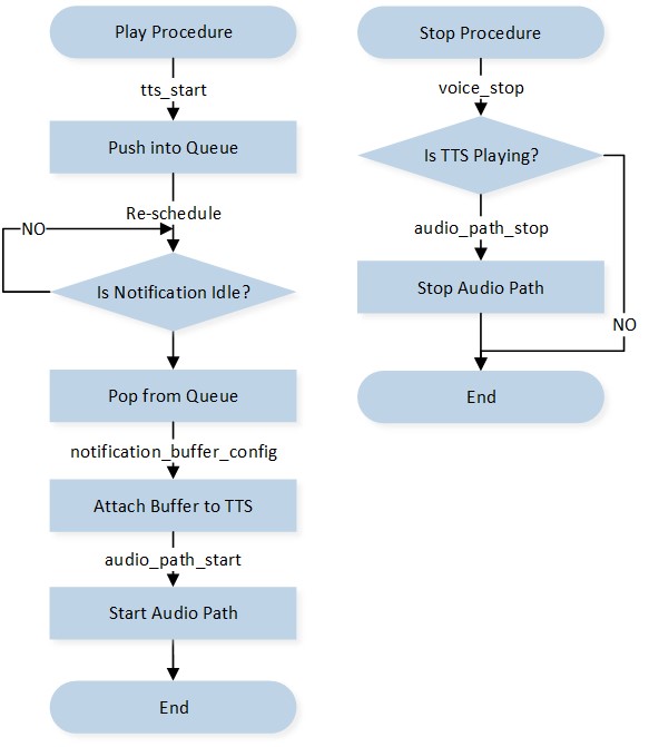
TTS synthesizes speech from normal language text for playback or to create voice files. The APIs used to control the TTS are illustrated in the below figure TTS Control Flow. The Application should follow the control flow outlined below:
The Application invokes the
tts_start()API to trigger the start procedure.The Notification module pushes this TTS activity into the queue.
If the Notification module is busy, the activity is pended for rescheduling. Otherwise, the activity is popped from the queue.
The Notification Buffer is attached to the TTS instance.
The TTS Audio Path is started.
The Application can stop the playing TTS by invoking the
tts_stop()API.
TTS Control Flow
Note
TTS and Voice Prompt have similar procedures within the Notification Module. Their main difference between them is that Voice Prompt’s stream source is from flash, while TTS’s stream source is from the Application layer.