ADC GDMA Mode
This sample code guide is designed to help users easily and comprehensively understand ADC sample. This sample demonstrates how ADC samples data in continuous mode by GDMA. This sample uses continuous mode of the ADC peripheral to measure voltage on P0_0 and P0_1.
Requirements
For hardware requirements, please refer to the Requirements.
Wiring
Connect P0_0 and P0_1 of EVB to external DC voltage source. Input voltage of P0_0 and P0_1 must range from 0 to 3.3V.
Configurations
The entry function is as follows, call this function in
main()to run this sample code. For more details, please refer to the Initialization.adc_gdma_demo();
Building and Downloading
For building and downloading, please refer to the Building and Downloading.
Experimental Verification
Press the Reset button on the EVB, ADC starts continuous sampling, and sample rawdata will be stored in array ADC_Buffer.
Code Overview
This section introduces the code and process description for initialization and corresponding function implementation in the sample.
Note
To use the mode, please turn off Charger auto enable and Battery detection support on the MCUConfig Tool. As shown in Turn Off Charger on the MCUConfig Tool.
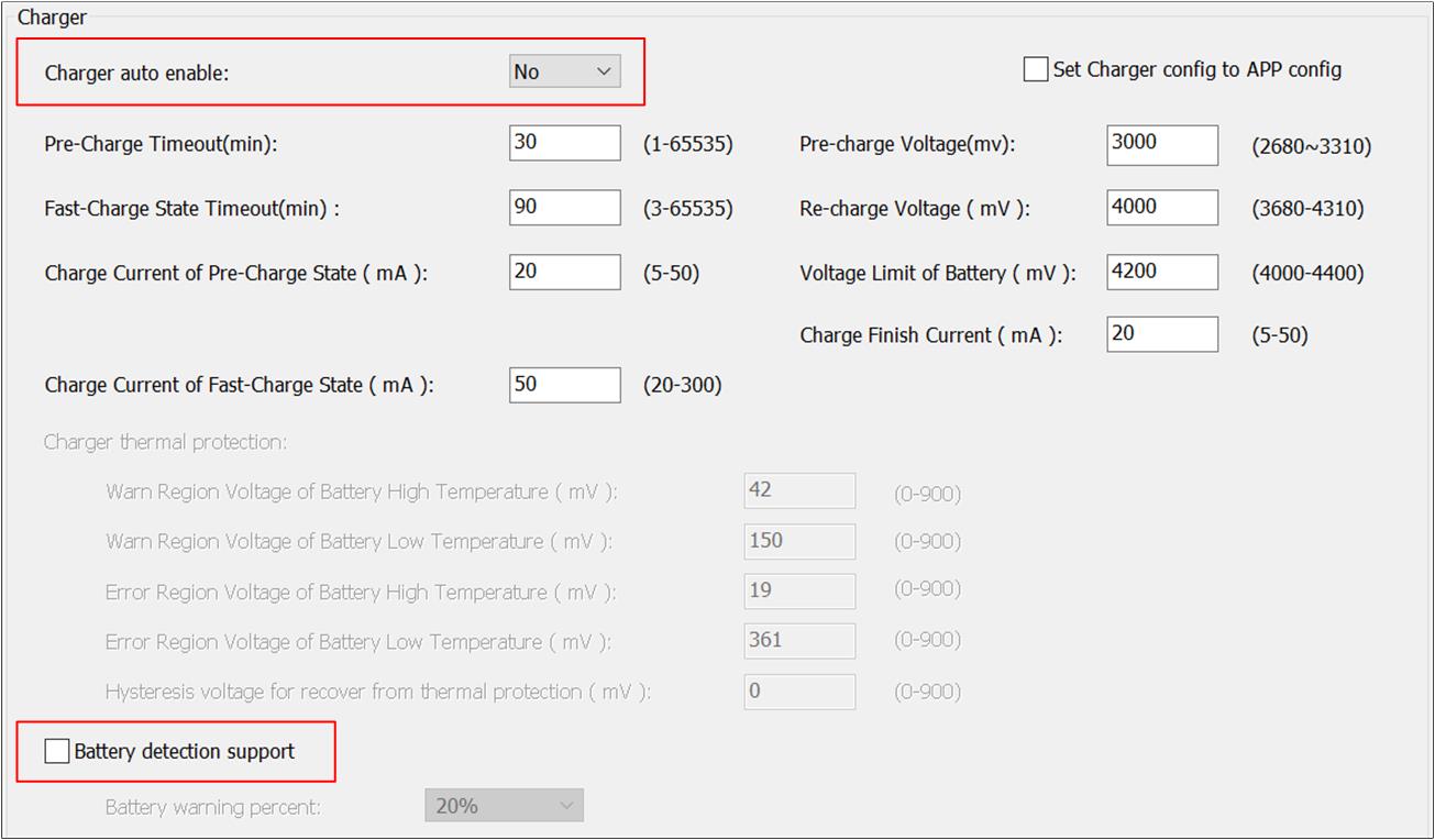
Turn Off Charger on the MCUConfig Tool
Source Code Directory
For project directory, please refer to Source Code Directory.
Source code directory:
sdk\src\sample\io_demo\gdma\adc_dma\adc_gdma_demo.c.
ADC Initialization
The initialization flow for peripherals can refer to Initialization Flow.
ADC continuous mode initialization flow is shown in the following figure.
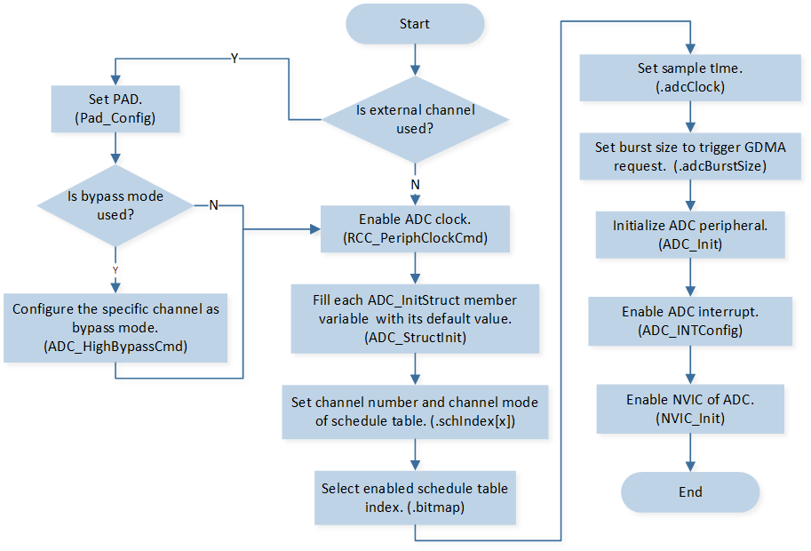
ADC Continuous Mode Initialization Flow Chart
Call
Pad_Config()andPinmux_Config()to initialize the pin.static void board_adc_init(void) { Pad_Config(ADC_0, PAD_SW_MODE, PAD_IS_PWRON, PAD_PULL_NONE, PAD_OUT_DISABLE, PAD_OUT_LOW); Pad_Config(ADC_1, PAD_SW_MODE, PAD_IS_PWRON, PAD_PULL_NONE, PAD_OUT_DISABLE, PAD_OUT_LOW); Pinmux_Config(ADC_0, IDLE_MODE); Pinmux_Config(ADC_1, IDLE_MODE); }
Call
RCC_PeriphClockCmd()to enable the ADC clock and function.Initialize the ADC peripheral:
Define the
ADC_InitTypeDeftypeadcInitStruct, and callADC_StructInit()to pre-filladcInitStructwith default values.Modify the
adcInitStructparameters as needed. The ADC initialization parameter configuration is shown in the table below.Call
ADC_Init()to initialize the ADC peripheral.
ADC Initialization Parameters ADC Hardware Parameters
Setting in the
adcInitStructVariablesADC
Bit Map
0x03
Schedule Index
Index 0 is set to
EXT_SINGLE_ENDED(0).Index 1 is set to
EXT_SINGLE_ENDED(1).Burst Size
1
Sample Time
FIFO Threshold Level
5
Call
ADC_INTConfig()to enable ADC FIFO read error interruptADC_INT_FIFO_RD_ERR.Call
NVIC_Init()to enable NVIC of ADC.
GDMA Initialization
GDMA initialization flow is shown in the following figure.
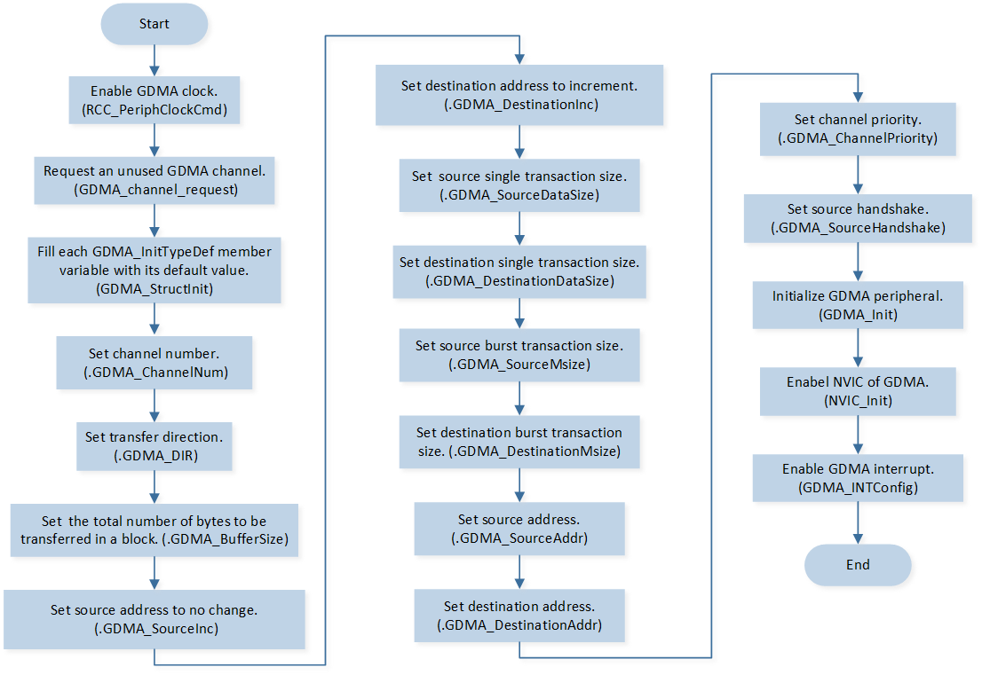
GDMA Initialization Flow Chart
Call
RCC_PeriphClockCmd()to enable the GDMA clock and function.Call
GDMA_channel_requestto request an unused GDMA channel.Initialize the GDMA peripheral:
Define the
GDMA_InitTypeDeftypeGDMA_InitStruct, and callGDMA_StructInit()to pre-fillGDMA_InitStructwith default values.Modify the
GDMA_InitStructparameters as needed. The GDMA initialization parameter configuration is shown in the table below.Call
GDMA_Init()to initialize the GDMA peripheral.
GDMA Initialization Parameters GDMA Hardware Parameters
Setting in the
GDMA_InitStructVariablesGDMA
Channel Num
ADC_DMA_CHANNEL_NUMTransfer Direction
Buffer Size
200
Source Address Increment or Fix
Destination Address Increment or Fix
Source Data Size
Destination Data Size
Source Burst Transaction Length
Destination Burst Transaction Length
Source Address
(uint32_t)(&(ADC->FIFO))Destination Address
(uint32_t)ADC_BufferSource Handshake
Call
NVIC_Init()to enable NVIC of GDMA.Call
GDMA_INTConfig()to enable GDMA transfer complete interruptGDMA_INT_Transfer.
Functional Implementation
Enable ADC Contiunous Sampling
Call
GDMA_Cmd()to enable GDMA.Call
ADC_Cmd()to enable ADC contiunous sampling.
ADC Interrupt Handle
When read the empty FIFO, ADC FIFO read error interrupt is triggered:
Call
ADC_GetIntFlagStatus()to checkADC_INT_FIFO_RD_ERRinterrupt status flag.Call
ADC_ClearINTPendingBit()to clearADC_INT_FIFO_RD_ERRinterrupt.
GDMA Interrupt Handle
When GDMA transfer is completed, transfer complete interrupt is triggered:
Call
GDMA_ClearINTPendingBit()to clearGDMA_INT_Transferinterrupt.Call
ADC_Cmd()to disable ADC.Call
GDMA_channel_release()to release the GDMA channel used by ADC.