Key - Level Trigger
This sample uses the GPIO input function to implement key functionality. The key is level-triggered.
Users can modify key information through different macro configurations. For specific macro configurations, refer to Configurations.
Requirements
For hardware requirements, please refer to the Requirements.
Wiring
Connect P0_0 and KEY1 on the EVB.
The hardware connection of GPIO key edge sample code is shown in the figure below.
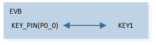
GPIO Key Sample Code Hardware Connection Diagram
Configurations
The following macros can be configured to modify key pin definitions.
#define KEY_PIN ADC_0The following macros can be configured to modify the debounce time of the key.
#define KEY_PRESS_DEBOUNCE_TIME       (30 * 1000)            //30ms
#define KEY_RELEASE_DEBOUNCE_TIME     (30 * 1000)            //30ms
The entry function is as follows, call this function in
main()to run this sample code. For more details, please refer to the Initialization.gpio_key();
Building and Downloading
For building and downloading, please refer to the Building and Downloading.
Experimental Verification
Press the Reset button on the EVB.
Press KEY1, the following message is printed in the Debug Analyzer.
debounce_hw_timer_callback: Key press
Release KEY1, the following message is printed in the Debug Analyzer.
debounce_hw_timer_callback: Key release
Code Overview
This section introduces the code and process description for initialization and corresponding function implementation in the sample.
Source Code Directory
The directory for project file and source code are as follows.
For project directory, please refer to Source Code Directory.
Source code directory:
sdk\sample\io_demo\gpio\key\level_tim\gpio_key.c.
Initialization
The initialization flow for peripherals can refer to Initialization Flow.
Call
hal_gpio_init()to enable GPIO clock.hal_gpio_init();
Call
hal_gpio_int_init()to initialize GPIO interrupt.hal_gpio_int_init();
Call
hal_gpio_init_pin()to initialize the GPIO peripheral and callhal_gpio_set_up_irq()to initialize interrupt-related parameters. The GPIO initialization parameters are configured as shown in the table below.
Key Hardware Parameters |
Key |
|---|---|
Pin Number |
|
GPIO Type |
|
GPIO Mode |
|
GPIO Pull Value |
|
Interrupt Type |
|
Interrupt Polarity |
|
Debounce Enable |
|
Call
hal_gpio_register_isr_callback()to register gpio interrupt callback.Call
hal_gpio_irq_enable()to enable gpio interrupt.Call
hw_timer_create()to create a hardware timer.
Functional Implementation
When KEY1 is pressed, the GPIO interrupt will be triggered. The interrupt handler function
key_handlerwill perform the following actions.Call
hal_gpio_irq_disable()to disable GPIO interrupt.Call
hal_gpio_get_input_level()to record current input level of key.Call
hw_timer_restart()to restart hardware timer.
static void key_handler(uint32_t key_index)
{
    /*  Disable GPIO interrupt */
    hal_gpio_irq_disable(key_index);

    key_status = hal_gpio_get_input_level(key_index);
    IO_PRINT_INFO1("key_handler: key_status %d", key_status);

    if (isPress == false)
    {
        hw_timer_restart(debounce_timer_handle, KEY_PRESS_DEBOUNCE_TIME);
    }
    else
    {
        hw_timer_restart(debounce_timer_handle, KEY_RELEASE_DEBOUNCE_TIME);
    }
}
When the timer expires, the
debounce_hw_timer_callbackwill be called.Call
hw_timer_stop()to stop hardware timer.Call
hal_gpio_get_input_level()to obtain the GPIO level and compare it with the level before the hardware timer started.If the levels are different.
Call
hal_gpio_irq_enable()to enable GPIO interrupt.The function ends.
If the levels are the same.
Based on the key’s level, change the interrupt polarity by calling
hal_gpio_irq_change_polarity().Call
hal_gpio_irq_enable()to enable GPIO interrupt.
static void debounce_hw_timer_callback(T_HW_TIMER_HANDLE handle)
{
     hw_timer_stop(debounce_timer_handle);

     if (key_status != hal_gpio_get_input_level(KEY_PIN))
     {
         hal_gpio_irq_enable(KEY_PIN);
         return;
     }

     if (key_status)
     {
         hal_gpio_irq_change_polarity(KEY_PIN, GPIO_IRQ_ACTIVE_LOW);
         isPress = false;
         IO_PRINT_INFO0("debounce_hw_timer_callback: Key release");
     }
     else
     {
         hal_gpio_irq_change_polarity(KEY_PIN, GPIO_IRQ_ACTIVE_HIGH);
         isPress = true;
         IO_PRINT_INFO0("debounce_hw_timer_callback: Key press");
     }
     hal_gpio_irq_enable(KEY_PIN);
 }