I2S GDMA Operation
This sample code demonstrates I2S master sending and receiving data via GDMA handshake as I2S masster. In this sample, the I2S is configured as the master, and the chip simultaneously sends data to the I2S slave and receives data sent by the I2S slave.
Requirements
For hardware requirements, please refer to the Requirements.
Wiring
Connect P0_0 to the LRCK of the I2S slave, connect P0_1 to the BCLK of the I2S slave, connect P0_2 to the SDI of the I2S slave, and connect P0_3 to the SDO of the I2S slave.
The hardware connection of I2S sample code is shown in the figure below.
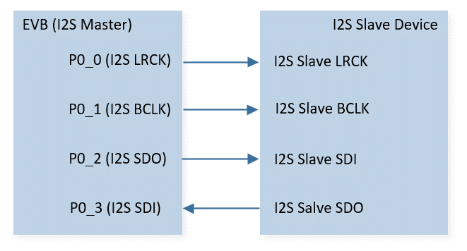
I2S Sample Code Hardware Connection Diagram
Configurations
The following macros can be configured to modify pin definitions.
#define I2S_LRCK_PIN P0_0#define I2S_BCLK_PIN P0_1#define I2S_SDO_PIN P0_2#define I2S_SDI_PIN P0_3
The entry function is as follows, call this function in
main()to run this sample code. For more details, please refer to the Initialization.i2s_master_dma_operation_demo();
Building and Downloading
For building and downloading, please refer to the Building and Downloading.
Experimental Verification
Code Overview
Source Code Directory
For project directory, please refer to Source Code Directory.
Source code directory:
sdk\src\sample\io_demo\i2s\dma_operation\i2s_master_dma_operation_demo.c.
Initialization
The initialization flow for peripherals can refer to Initialization Flow.
I2S initialization flow is shown in the following figure.
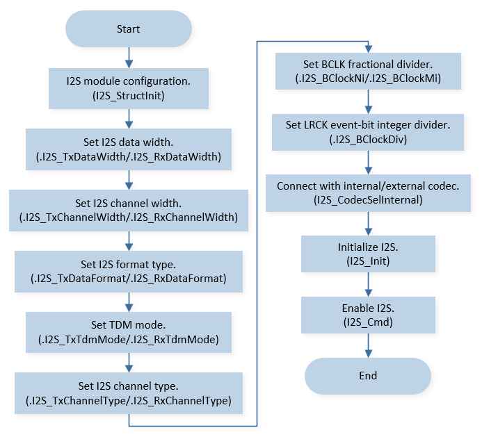
I2S Master Init Flow Chart
Note
As mentioned in PINMUX and PAD function descriptions, I2S PAD should be configured as software mode and pulled down when I2S is disabled to prevent PAD from floating during low power mode.
Call
Pad_Config()andPinmux_Config()to initialize the pin.static void board_i2s_init(void) { /* set PAD_SW_MODE & PAD_PULL_DOWN when I2S disable to prevent PAD floating */ Pad_Config(I2S_BCLK_PIN, PAD_PINMUX_MODE, PAD_IS_PWRON, PAD_PULL_NONE, PAD_OUT_ENABLE, PAD_OUT_LOW); Pad_Config(I2S_LRCK_PIN, PAD_PINMUX_MODE, PAD_IS_PWRON, PAD_PULL_NONE, PAD_OUT_ENABLE, PAD_OUT_LOW); Pad_Config(I2S_SDO_PIN, PAD_PINMUX_MODE, PAD_IS_PWRON, PAD_PULL_NONE, PAD_OUT_ENABLE, PAD_OUT_LOW); Pad_Config(I2S_SDI_PIN, PAD_PINMUX_MODE, PAD_IS_PWRON, PAD_PULL_NONE, PAD_OUT_ENABLE, PAD_OUT_LOW); Pinmux_Config(I2S_BCLK_PIN, I2S_BCLK_PINMUX); Pinmux_Config(I2S_LRCK_PIN, I2S_LRCK_PINMUX); Pinmux_Config(I2S_SDO_PIN, I2S_SDO_PINMUX); Pinmux_Config(I2S_SDI_PIN, I2S_SDI_PINMUX); }
Initialize the I2S peripheral:
Define the
I2S_InitTypeDeftypeI2S_InitStruct, and callI2S_StructInit()to pre-fillI2S_InitStructwith default values.Modify the
I2S_InitStructparameters as needed. The I2S initialization parameter configuration is shown in the table below.Call
I2S_Init()to initialize the I2S peripheral.
I2S Initialization Parameters I2S Hardware Parameters
Setting in the
I2S_InitStructI2S
Device Role
Bit Clock Divider (Mi)
0x271
Bit Clock Divider (Ni)
0x30
LR Clock Divider
0x3F
Tx Data Width
Rx Data Width
Tx Channel Width
Rx Channel Width
Tx Channel Type
Rx Channel Type
Tx Data Format
Rx Data Format
Call
RCC_PeriphClockCmd()to enable the GDMA clock and function for I2S TX.Call
GDMA_channel_requestto request an unused GDMA channel for I2S TX.Initialize the GDMA peripheral for I2S TX:
Define the
GDMA_InitTypeDeftypeGDMA_InitStruct, and callGDMA_StructInit()to pre-fillGDMA_InitStructwith default values.Modify the
GDMA_InitStructparameters as needed. The GDMA initialization parameter configuration is shown in the table below.Call
GDMA_Init()to initialize the GDMA peripheral.
GDMA Initialization Parameters GDMA Hardware Parameters
Setting in the
GDMA_InitStructVariablesGDMA
Channel Num
I2S_TX_DMA_CHANNEL_NUMTransfer Direction
Buffer Size
I2S_DMA_BUF_LENSource Address Increment or Fix
Destination Address Increment or Fix
Source Data Size
Destination Data Size
Source Burst Transaction Length
Destination Burst Transaction Length
Source Address
(uint32_t)(i2s_send_buff)Destination Address
I2S_TX_ADDRDestination Handshake
I2S_TX_DMA_HANDSHAKECall
NVIC_Init()to enable NVIC of GDMA for I2S TX.Call
RCC_PeriphClockCmd()to enable the GDMA clock and function for I2S RX.Call
GDMA_channel_requestto request an unused GDMA channel for I2S RX.Initialize the GDMA peripheral for I2S RX:
Define the
GDMA_InitTypeDeftypeGDMA_InitStruct, and callGDMA_StructInit()to pre-fillGDMA_InitStructwith default values.Modify the
GDMA_InitStructparameters as needed. The GDMA initialization parameter configuration is shown in the table below.Call
GDMA_Init()to initialize the GDMA peripheral.
GDMA Initialization Parameters GDMA Hardware Parameters
Setting in the
GDMA_InitStructVariablesGDMA
Channel Num
I2S_RX_DMA_CHANNEL_NUMTransfer Direction
Buffer Size
I2S_DMA_BUF_LENSource Address Increment or Fix
Destination Address Increment or Fix
Source Data Size
Destination Data Size
Source Burst Transaction Length
Destination Burst Transaction Length
Source Address
I2S_RX_ADDRDestination Address
(uint32_t)(i2s_recv_buff)Source Handshake
I2S_RX_DMA_HANDSHAKECall
NVIC_Init()to enable NVIC of GDMA for I2S RX.Call
GDMA_INTConfig()to enable GDMA transfer complete interrupt.Call
GDMA_Cmd()to enable GDMA.
Functional Implementation
TX GDMA Handshake Operation
Turn on the peripheral clock source of the GDMA.
I2S TX and GDMA initialization: Set GDMA handshake with I2S TX.
Enable the
GDMA_INT_Transferinterrupt and enable GDMA.Invoke
I2S_Cmd()to generate LRCK and start retrieving data from TX FIFO.Initiate GDMA request if TX FIFO water level is lower than TX GDMA burst size.
Trigger GDMA transfer interrupt and wait for GDMA transfer to complete.
Clear
GDMA_INT_Transferinterrupt.
The flow chart of I2S TX GDMA handshake operation is shown in the following figure.
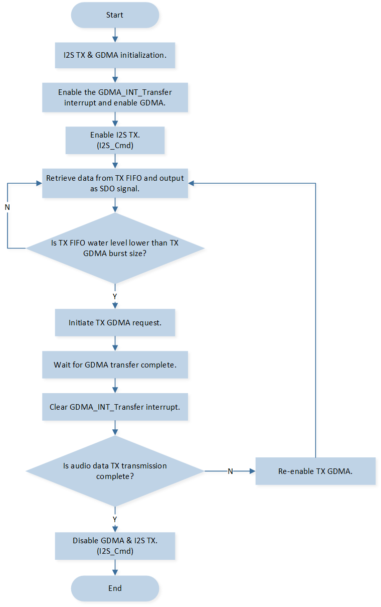
I2S TX GDMA Flow
RX GDMA Handshake Operation
Turn on the peripheral clock source of the GDMA.
I2S RX and GDMA initialization: Set GDMA handshake with I2S RX.
Enable the
GDMA_INT_Transferinterrupt and enable GDMA.Invoke
I2S_Cmd()to generate LRCK and start sending data to RX FIFO.Wait for RX FIFO data to exceed RX GDMA burst size and initiate GDMA request.
Trigger GDMA transfer interrupt and wait for GDMA transfer to complete.
Clear
GDMA_INT_Transferinterrupt.
The flow chart of I2S RX GDMA handshake operation is shown in the following figure.
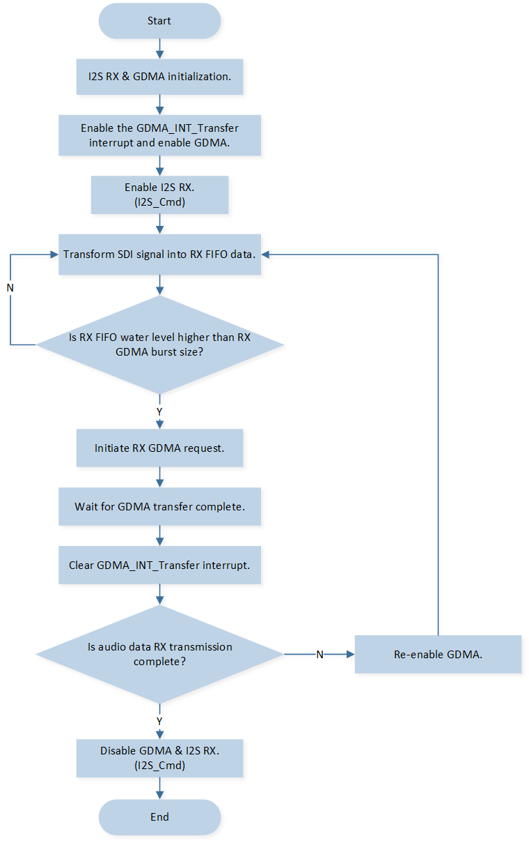
I2S RX GDMA Flow
Interrupt Handle
When I2S TX or RX GDMA transfer is completed, transfer complete interrupt is triggered:
Call
GDMA_ClearAllTypeINT()to clear all interrupt of GDMA Channelx.Call
GDMA_Cmd()to re-enable GDMA and conitune data transfer.Alternatively, after the data transfer is complete, call
GDMA_Cmd()to disable GDMA, and then callI2S_Cmd()to disable I2S.