KeyScan in Active Mode
This sample code guide is designed to help users easily and comprehensively understand KeyScan sample. This sample demonstrates how KeyScan works in active mode.
Requirements
For hardware requirements, please refer to the Requirements.
Wiring
The EVB is connected to a matrix keyboard module, connect P0_2 to ROW0, P0_3 to ROW1, P0_0 to COLUMN0, and P0_1 to COLUMN1. The hardware connection of KeyScan sample code is shown in the figure below.
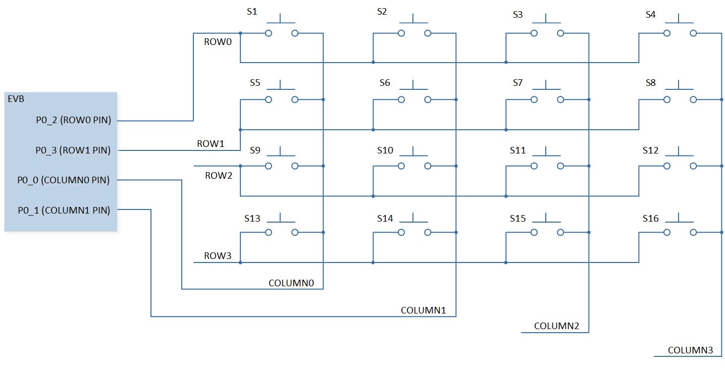
KeyScan Sample Code Hardware Connection Diagram
Configurations
The following macros can be configured to modify pin definitions.
#define COLUMN0 ADC_0#define COLUMN1 ADC_1#define ROW0 ADC_2#define ROW1 ADC_3
The entry function is as follows, call this function in
main()to run this sample code. For more details, please refer to the Initialization.keyscan_demo();
Building and Downloading
For building and downloading, please refer to the Building and Downloading.
Experimental Verification
Press the Reset button on the EVB, when keys are pressed, KeyScan starts scan. After the scan ends, it enters the KeyScan interrupt and prints the key information.
io_demo_task: pKeyData->key[xx] xx
After all the keys are released, print the following log.
io_demo_task: All key release
Code Overview
This section introduces the code and process description for initialization and corresponding function implementation in the sample.
Source Code Directory
For project directory, please refer to Source Code Directory.
Source code directory:
sdk\src\sample\io_demo\keyscan\active\keyscan_demo.c.
Initialization
The initialization flow for peripherals can refer to Initialization Flow.
KeyScan initialization flow is shown in the following figure.
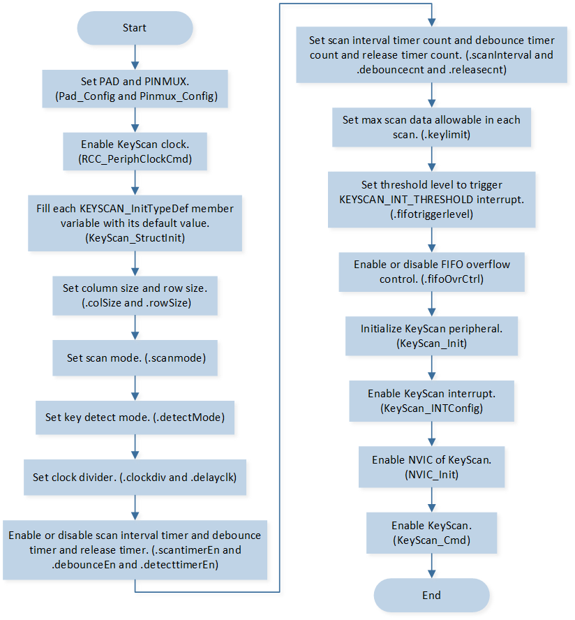
KeyScan Initialization Flow Chart
Call
Pad_Config()andPinmux_Config()to initialize the pin.static void board_keyscan_init(void) { Pad_Config(COLUMN0, PAD_PINMUX_MODE, PAD_IS_PWRON, PAD_PULL_NONE, PAD_OUT_ENABLE, PAD_OUT_LOW); Pad_Config(COLUMN1, PAD_PINMUX_MODE, PAD_IS_PWRON, PAD_PULL_NONE, PAD_OUT_ENABLE, PAD_OUT_LOW); Pad_Config(ROW0, PAD_PINMUX_MODE, PAD_IS_PWRON, PAD_PULL_UP, PAD_OUT_DISABLE, PAD_OUT_LOW); Pad_Config(ROW1, PAD_PINMUX_MODE, PAD_IS_PWRON, PAD_PULL_UP, PAD_OUT_DISABLE, PAD_OUT_LOW); Pinmux_Config(COLUMN0, KEY_COL_0); Pinmux_Config(COLUMN1, KEY_COL_1); Pinmux_Config(ROW0, KEY_ROW_0); Pinmux_Config(ROW1, KEY_ROW_1); }
Call
RCC_PeriphClockCmd()to enable the KeyScan clock and function.Initialize the KeyScan peripheral:
Define the
KEYSCAN_InitTypeDeftypeKeyScan_InitStruct, and callKeyScan_StructInit()to pre-fillKeyScan_InitStructwith default values.Modify the
KeyScan_InitStructparameters as needed. The KeyScan initialization parameter configuration is shown in the table below.Call
KeyScan_Init()to initialize the KeyScan peripheral.
KeyScan Initialization Parameters KeyScan Hardware Parameters
Setting in the
KeyScan_InitStructKeyScan
Column Size
2
Row Size
2
Scan Interval
0x80
Call
KeyScan_INTConfig()to enable the KeyScan scan end interruptKEYSCAN_INT_SCAN_ENDand the KeyScan all release interruptKEYSCAN_INT_ALL_RELEASE.Call
NVIC_Init()to enable NVIC of KeyScan.Call
KeyScan_Cmd()to enable KeyScan.
Functional Implementation
Interrupt Handle
After the scan key matrix is completed, the KeyScan scan end interrupt is triggered.
Call
KeyScan_GetFlagState()to checkKEYSCAN_INT_FLAG_SCAN_ENDinterrupt flag state.Call
KeyScan_INTMask()to maskKEYSCAN_INT_SCAN_ENDinterrupt.Call
KeyScan_GetFlagState()to check the FIFO empty flag state, ifKEYSCAN_FLAG_EMPTYflag is set:Call
KeyScan_GetFifoDataNum()to get KeyScan FIFO data number.Call
KeyScan_Read()to read data from KeyScan FIFO.If new buttons are pressed:
Send a message to the task, and after the task receives the message, it will print log.
Call
KeyScan_ClearINTPendingBit()to clearKEYSCAN_INT_SCAN_ENDinterrupt.Call
KeyScan_INTMask()to unmaskKEYSCAN_INT_SCAN_ENDinterrupt.
If no new buttons are pressed:
Call
KeyScan_ClearINTPendingBit()to clearKEYSCAN_INT_SCAN_ENDinterrupt.Call
KeyScan_INTMask()to unmaskKEYSCAN_INT_SCAN_ENDinterrupt.
When the release time count reaches the set value, if no key is pressed, the KeyScan all release interrupt is triggered.
Call
KeyScan_GetFlagState()to checkKEYSCAN_INT_FLAG_ALL_RELEASEinterrupt flag state.Call
KeyScan_INTMask()to maskKEYSCAN_INT_ALL_RELEASEinterrupt.Send a message to the task, and after the task receives the message, it will print log.
Call
KeyScan_ClearINTPendingBit()to clearKEYSCAN_INT_ALL_RELEASEinterrupt.Call
KeyScan_INTMask()to unmaskKEYSCAN_INT_ALL_RELEASEinterrupt.