LPC Comparator Function
This sample code guide is designed to help users easily and comprehensively understand LPC sample. This sample demonstrates LPC comparator function.
Requirements
For hardware requirements, please refer to the Requirements.
Wiring
Connect P0_0 of EVB to an external DC voltage source.
Configurations
The following macros can be configured to modify pin definitions.
#define LPC_CAPTURE_PIN ADC_0
The following macros can be configured to modify the LPC comparator value.
#define LPC_COMP_VALUE 0x4
The entry function is as follows, call this function in
main()to run this sample code. For more details, please refer to the Initialization.lpc_comparator_demo();
Building and Downloading
For building and downloading, please refer to the Building and Downloading.
Experimental Verification
Press the Reset button on the EVB, adjust the DC voltage source repeatedly, when the input voltage on P0_0 is detected to be higher than 400mV for 4 times, it triggers the interrupt and prints log in Debug Analyzer.
lpc_rtc_handler: lpc_counter_value 4
Code Overview
This section introduces the code and process description for initialization and corresponding function implementation in the sample.
Source Code Directory
For project directory, please refer to Source Code Directory.
Source code directory:
sdk\src\sample\io_demo\lpc\comparator\lpc_comparator_demo.c.
Initialization
The initialization flow for peripherals can refer to Initialization Flow.
LPC initialization flow is shown in the following figure.
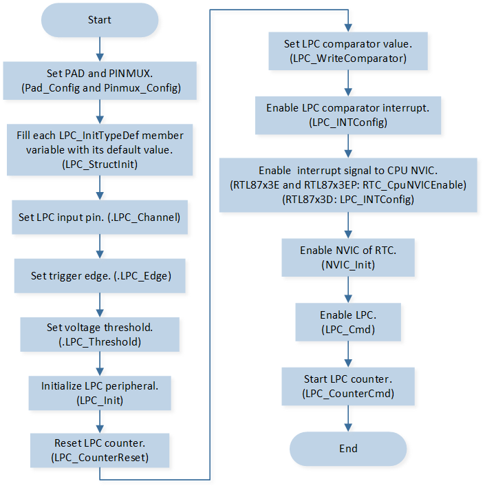
LPC Initialization Flow Chart
Call
Pad_Config()andPinmux_Config()to initialize the pin.static void board_lpc_init(void) { Pad_Config(LPC_CAPTURE_PIN, PAD_PINMUX_MODE, PAD_IS_PWRON, PAD_PULL_NONE, PAD_OUT_DISABLE, PAD_OUT_HIGH); Pinmux_Config(LPC_CAPTURE_PIN, IDLE_MODE); }
Initialize the LPC peripheral:
Define the
LPC_InitTypeDeftypeLPC_InitStruct, and callLPC_StructInit()to pre-fillLPC_InitStructwith default values.Modify the
LPC_InitStructparameters as needed. The LPC initialization parameter configuration is shown in the table below.Call
LPC_Init()to initialize the LPC peripheral.
LPC Initialization Parameters LPC Hardware Parameters
Setting in the
LPC_InitStructLPC
Channel
LPC_CAPTURE_PINEdge
Threshold Voltage
Call
LPC_CounterReset()to reset the LPC counter.Call
LPC_WriteComparator()to set LPC comparator value.Call
LPC_INTConfig()to enable the LPC comparator interruptLPC_INT_COUNT_COMP.For RTL87x3D, call
LPC_INTConfig()to enable interrupt signal to CPU NVIC, for RTL87x3E and RTL87x3EP, callRTC_CpuNVICEnable()to enable interrupt signal to CPU NVIC.For RTL87x3D, call
NVIC_Init()to enable NVIC of LPC, for RTL87x3E and RTL87x3EP, callNVIC_Init()to enable NVIC of RTC.Call
LPC_Cmd()to enable the LPC.Call
LPC_CounterCmd()to enable the LPC counter.
Functional Implementation
Interrupt Handle
LPC interrupt handle flow is shown in the figure below.
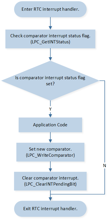
LPC Interrupt Handle Flow Chart
When the input voltage on P0_0 is detected to be higher than 400mV for 4 times, it triggers an interrupt:
Call
LPC_GetINTStatus()to checkLPC_INT_COUNT_COMPinterrupt status flag.Call
LPC_ReadCounter()to read LPC counter value.Call
LPC_WriteComparator()to set the LPC comparator value.Call
LPC_ClearINTPendingBit()to clear the LPC comparator interruptLPC_INT_COUNT_COMP.