This document aims to provide operational guidance for users who use MP Tool in mass production.
It is important to note that this document is applicable to the RTL8752, RTL8762, RTL8771, RTL8772, RTL8777 series of chips.
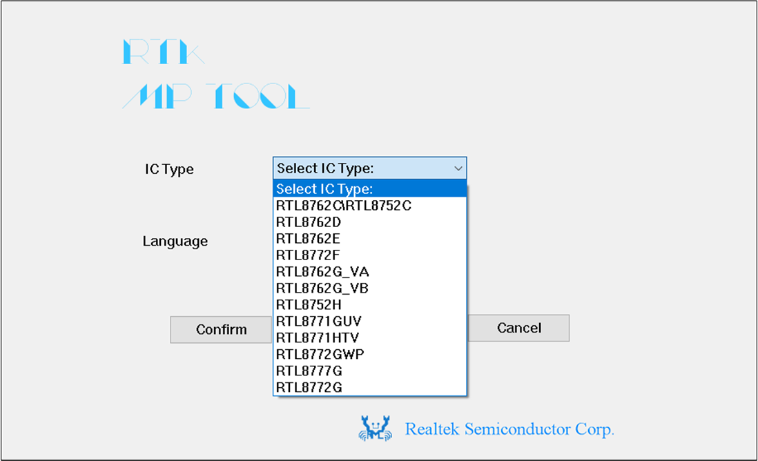
The RTL8762G_VB is used as an example in this document.
Debug Mode: used for development and debugging purposes by developers.
Supported Functions
Detailed Description
UART Communication Interface
The MP Tool only supports UART communication in MP Mode.
Multi-port Download
The MP Tool can download up to 24 ports simultaneously in MP Mode. When downloading more than eight ports, the tool will do it in batches, with a maximum of eight ports downloaded at a time.
After each batch, a dialog box will appear displaying the downloading results for each port.
Package File Download
Only package files can be downloaded in MP Mode.
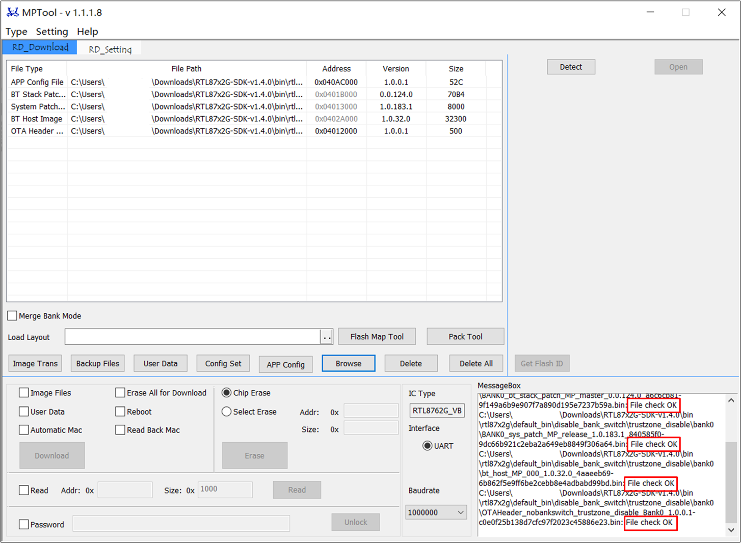
File Type Check
MP Tool will check the IC type of the file, and incorrect files cannot be loaded.
One-Button Download
To reduce operational errors during mass production, MP Tool defaults to One-Button download mode.
Lock and Unlock Setting
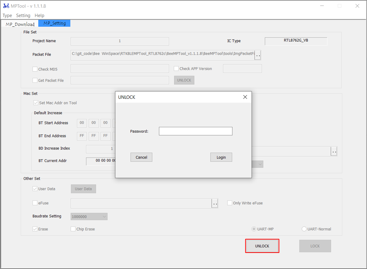
To avoid operational errors on the factory side during mass production, MP Tool provides [LOCK] 和 [UNLOCK] to lock various parameters of the [MP_Setting] interface.
For detailed instructions, please refer to LOCK and UNLOCK.
Set Unique Mode
In this mode, only one instance of the MP Tool can be opened at a time.
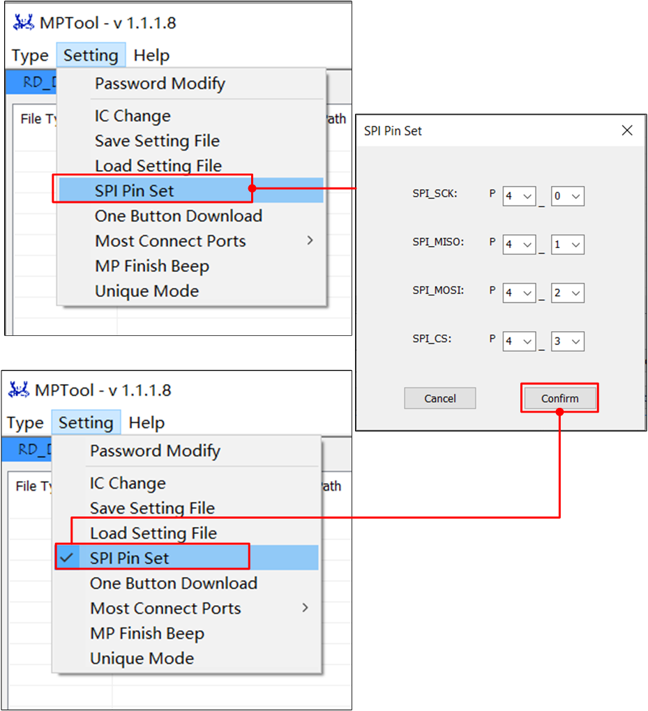
SPI Pin Set
Support for configuring SPI pin in the menu bar to write data to external flash. For detailed instructions, please refer to External Flash Download.
Multi-ways to Set MAC
During mass production, MP Tool provides various methods for updating Mac address, such as auto increased by Tool, get BT Address from a file, entering BT addresses via
the UI and so on. For detailed instructions, please refer to BT Address Settings in MP Mode.
eFuse Download
Support the standalone programming of eFuse file in MP Mode.
Users' Data Download
Users' specific data files can be programmed through the User Data method. For detailed instructions, please refer to User Data Download.
Supported Functions
Detailed Description
UART Communication Interface
In Debug Mode, MP Tool supports UART interface communication.
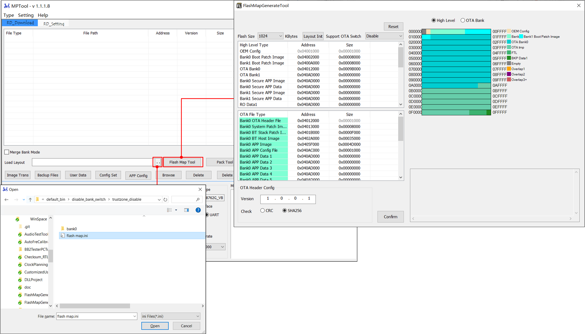
Flash Map Generate Tool
In Debug Mode, users can call the Flash Map Generate Tool. For detailed instructions, please refer to Flash Map Generate Tool
MP Pack Tool
In Debug Mode, users can call the MP Pack Tool. For detailed instructions, please refer to MP Pack Tool.
Multi-ports Download
MP Tool supports programming up to eight ports simultaneously over the UART interface in Debug Mode.
Download Separated Files
MP Tool supports programming of individual image files but does not support programming of package files in Debug Mode.
Config File Set
In Debug Mode, MP Tool supports configuring IC Config parameters and generating a config file. This file can be directly programmed into the chip or
packed in a package file for mass production programming.
Image Conversion
In Debug Mode, MP Tool can modify the address of some specific images using the [Image Trans]. For detailed instructions, please refer to Image Trans.
Image Address Configuration
In Debug Mode, MP Tool supports importing the flashmap.ini file to set the starting address of the image.
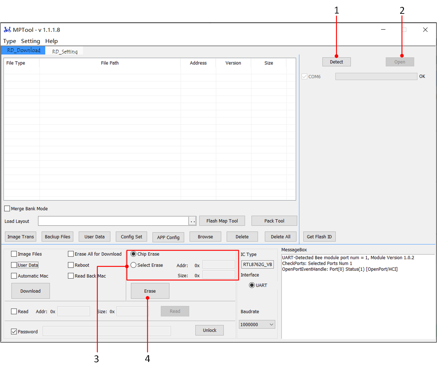
Erase Flash
In Debug Mode, the MP Tool supports erasing the flash, including the options for full chip erase and selective erase of fixed address and size.
For detailed instructions, please refer to Erase Flash.
Read Flash Back
In Debug Mode, the MP Tool supports reading back the flash and saving it as a .bin file, with each read-back limited to a maximum size of 32 Mbytes.
For detailed instructions, please refer to Flash Read Back and Save.
Backup Files
In Debug Mode, the MP Tool supports backing up all files configured at file loading location to the Backup folder. For detailed instructions, please refer to Back Up Files.
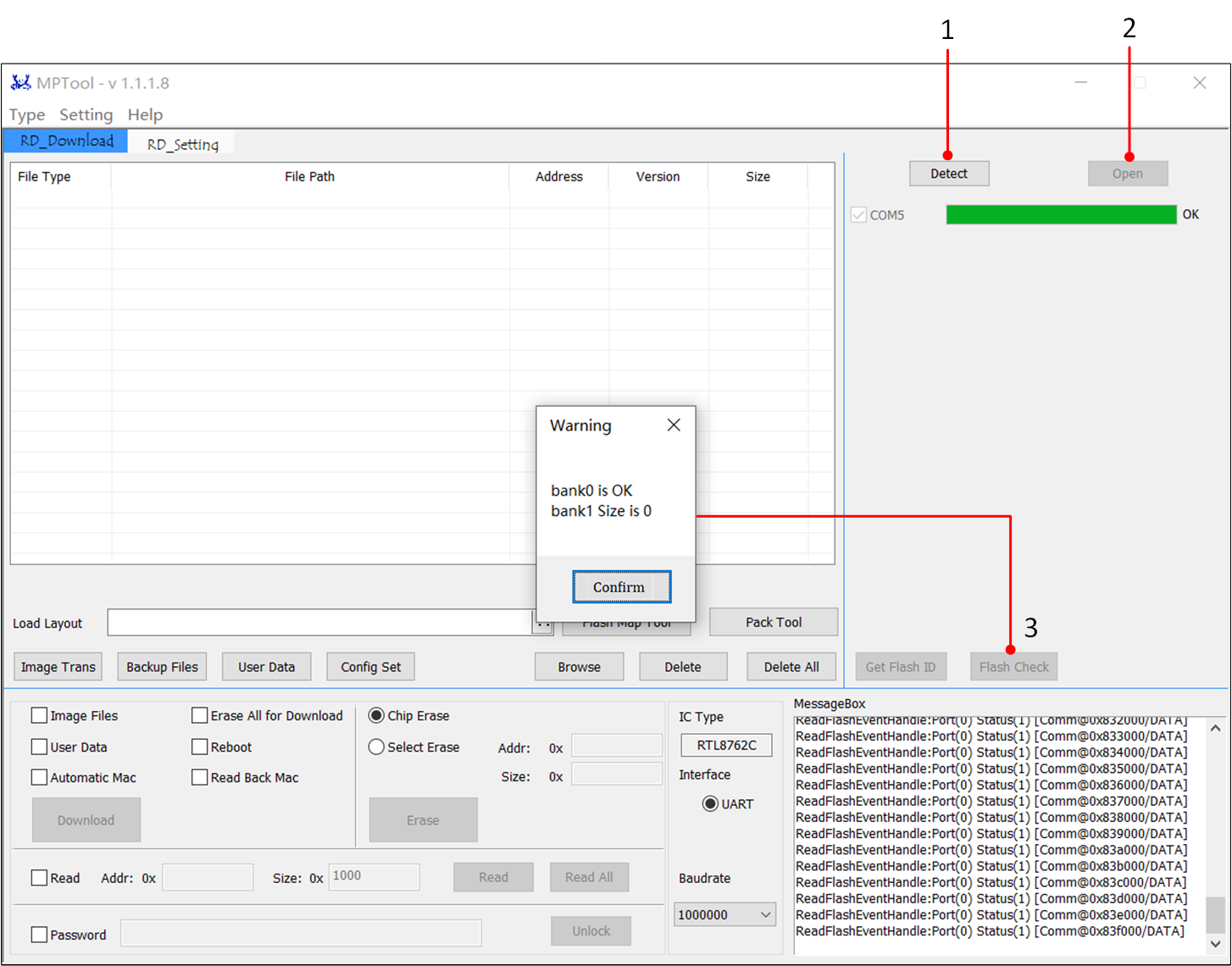
Flash Check
In Debug Mode, the MP Tool supports reading back data from the Flash to determine if it can boot properly. For detailed instructions, please refer to Flash Check.
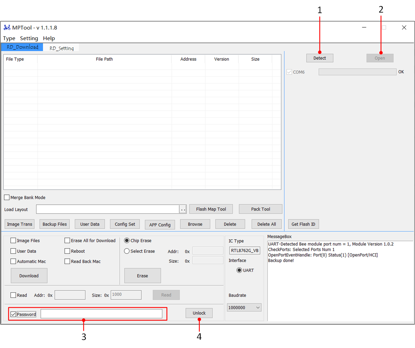
Password to Unlock Flash
In Debug Mode, the MP Tool supports entering a password to unlock a locked Flash for debugging purposes. For detailed instructions, please refer to Password.
Update MAC
In Debug Mode, only automatic increment or read-back mac is supported as an update method. If users need to update the Bluetooth address, simply check the corresponding update method before downloading, and only one of the two options can be selected.
Users' Data Download
On the User Data page, the tool supports custom data settings. For detailed instructions, please refer to User Data Download.
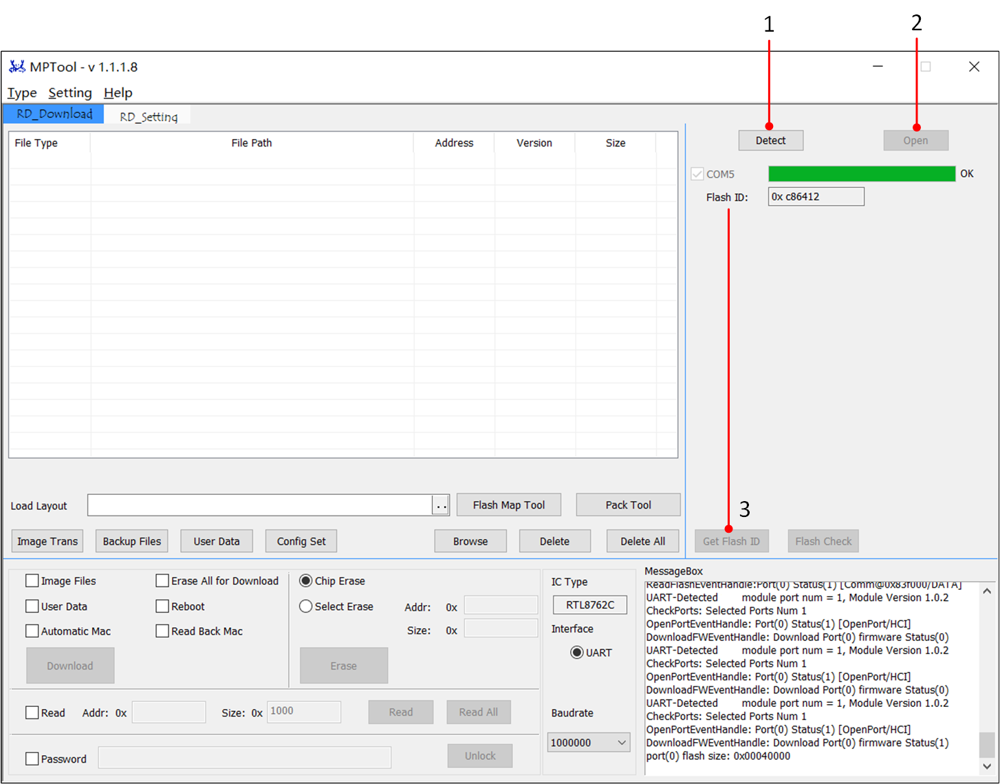
Getting Flash ID
In Debug Mode, users can obtain the ID of the connected flash. For detailed instructions, please refer to Get Flash ID.
Note
The Debug Mode is enabled by default. If the user wants to disable this feature while using it in the factory, they can refer to Disable Debug Mode.
All operational procedures in the document are based on the chip being in its factory state, where the chip has not been flashed with an Image File. For flash chips that have already been flashed, the flash content needs to be erased to restore it to the factory state.
System: MP Tool only supports Windows 7 SP1 and above systems.
Port: MP Tool will detect all the serial ports in the system, and unrelated COM ports may cause the tool to fail to open.
Note
If there are too many irrelevant ports in the PC (total number of download ports and irrelevant ports exceeds the number of 8), the RTL87xxx device will be captured by other irrelevant ports, resulting in the RTL87xxx device being unable to download.
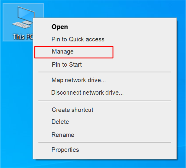
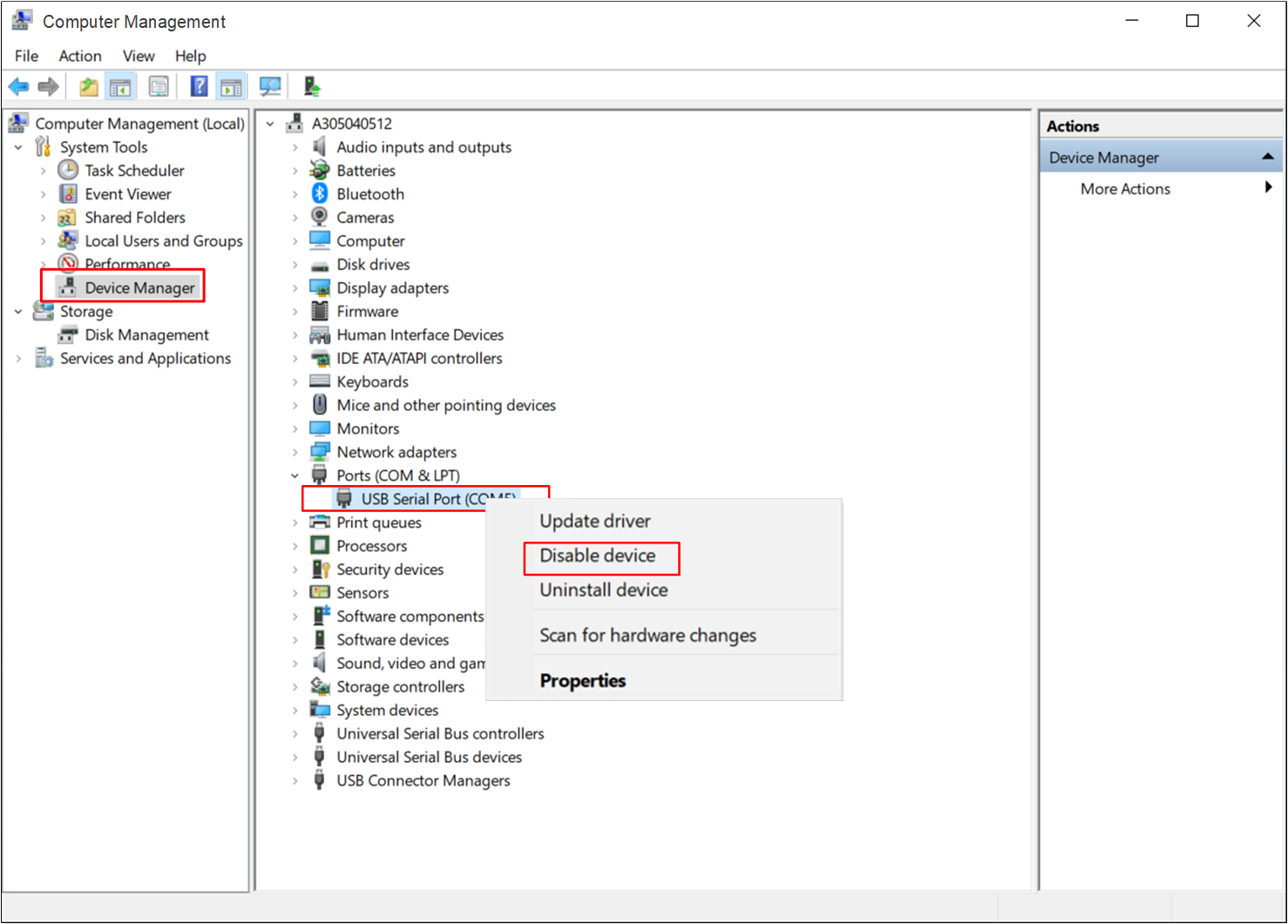
Users need to turn off irrelevant ports before downloading. The method to close the serial port is as follows.
Right-click on Computer icon, and select Manage in the menu.
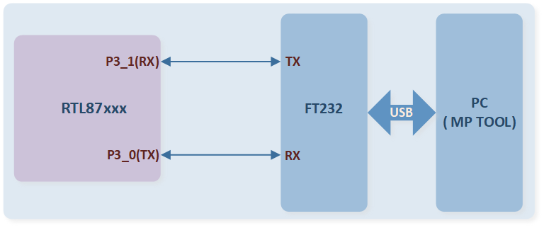
MP Tool only supports downloading with UART interface. Using UART requires P3_0(UART_TX) and P3_1(UART_RX) as the downloading ports.
Note
Try not to multiplex the pins that are already used by the downloading interface.
If the pins used by the downloading interface are multiplexed on the hardware, it is necessary to check the electrical characteristics. For example, the load on the pins can cause changes in the waveform of the downloading interface, leading to issues with the downloading process.
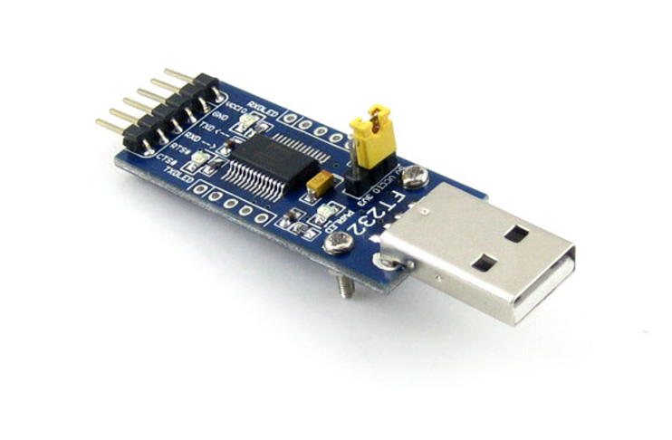
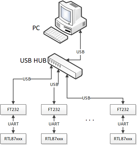
MP Tool supports downloading multiple ICs simultaneously, including one-to-one and one-to-many downloading. It is recommended to use FT232 USB to UART converter boards for better stability.
When using a one-to-many downloading method, if the USB port uses the PC's USB port or a USB HUB without external power supply, UART downloading may fail due to insufficient power supply capacity of the USB port.
It is recommended to use a USB HUB with external power supply to ensure stable downloading, as shown in the figure below.
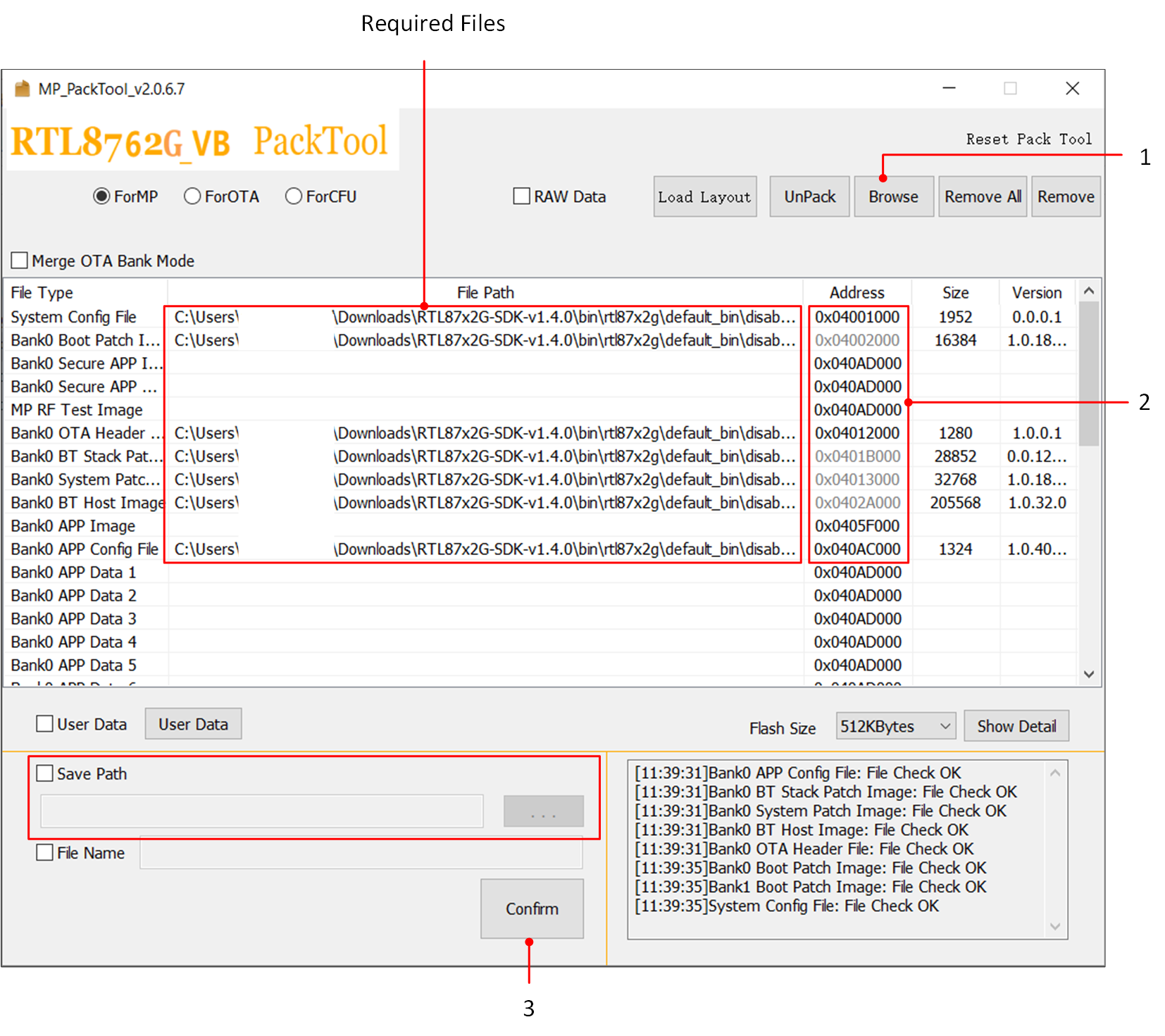
The generation of a package file requires the use of MP Pack Tool, with the generation steps as follows:
In Debug Mode, the MP Pack Tool can be opened by clicking the Pack Tool button; It can also be executed independently from the tools folder within the MP Kits.
Click Browse to import the image to be packaged.
Modify the starting Address of the image (if the flashmap.ini is imported, then modifying the Address is not necessary).
Select the save path as needed, and click Confirm to generate the packet file required for downloading.
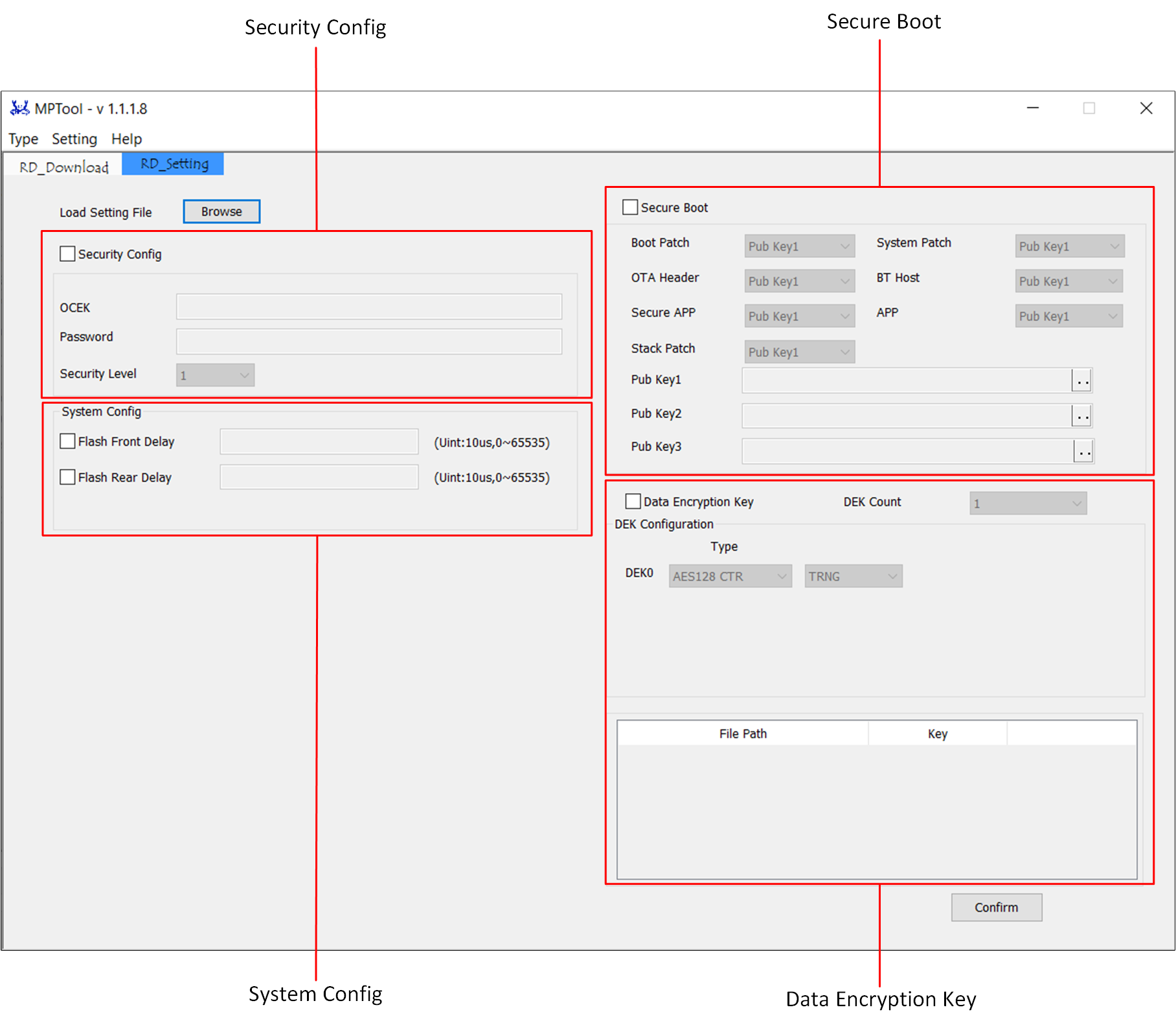
Users can enter or import OCEK and password plaintext click the Browse, and select the desired encryption level.
For detailed instructions, please refer to Security.
Used to configure the delay before and after Flash Initialization.The unit for Flash Delay is 10 us. When adjusting these two values, it is necessary to refer to the corresponding Flash Datasheet.
Flash Front Delay: Used to control the delay to wait for the power voltage to rise to the minimum operating voltage for the Flash.
Flash Rear Delay: Used to control the time to wait for the Flash to return to Standby status after the Reset command.
Used to ensure the integrity and authenticity of images, sha256 is used for integrity and ECDSA is used for authenticity. If any image authenticated fail, IC will reset or hang without jumping into the un-authenticated image.
Used to generate the key for encrypting data.
After configuring according to the requirements, finally click the Confirm button to generate the configuration file eFuseWriteFile.json for eFuse downloading.
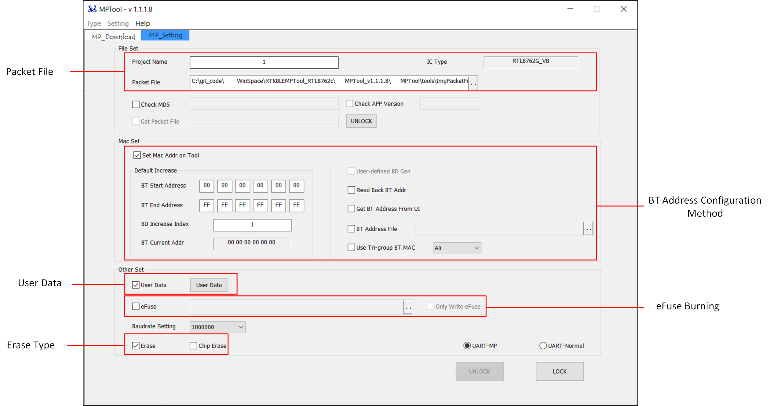
Click the .. next to the [Packet File] section to import the packet file that needs to be programmed.
MP Tool supports changing BT address through a txt file, automatically generating Bluetooth addresses through the tool, and generating Bluetooth addresses from user-provided library files. Developers can make selections through the relevant controls in the interface. For detailed instructions, please refer to BT Address Settings in MP Mode.
After checking the User Data, users can edit and add the user-defined data to be downloaded in the pop-up dialog. For detailed instructions, please refer to User Data Download.
After checking the eFuse, users can add the eFuse to be downloaded.
If the Flash can be programmed under 2.5V voltage, users can check the eFuse check box when programming the Flash, and uncheck Only Write eFuse, and download both the Flash and eFuse at the same time.
If Flash does not support programming under 2.5V voltage, users need to program eFuse separately. Do not check the eFuse when downloading Flash, then programming eFuse alone, check the eFuse checkbox, and check Only Write eFuse to program eFuse alone.
If the entire flash needs to be erased before programming, check the Chip Erase checkbox. If the Erase checkbox is checked, only the flash in the area that needs to be programmed will be erased.
Please click LOCK button to generate settings after configuring parameters.
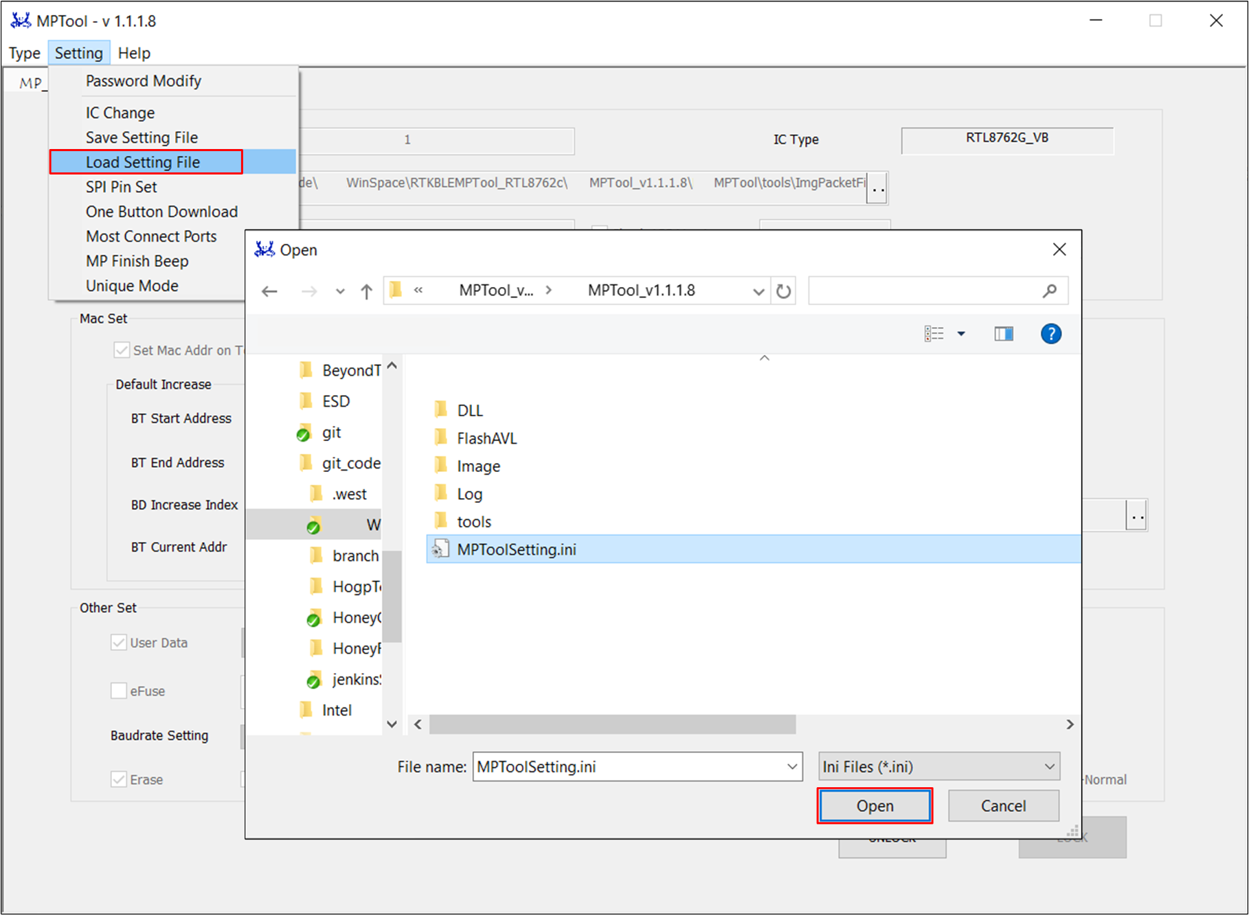
MP Tool supports automatic parameter configuration by loading configuration files. Developers need to generate the configuration file locally and provide it to the factory side.
Factory operators only need to load the configuration through the [Load Settings] feature in the tool, as shown in the figure below.
MPToolSetting.ini file needs to be in the same directory as the downloaded packet files, otherwise, there will be an error of Download Image: Load image packet failed.
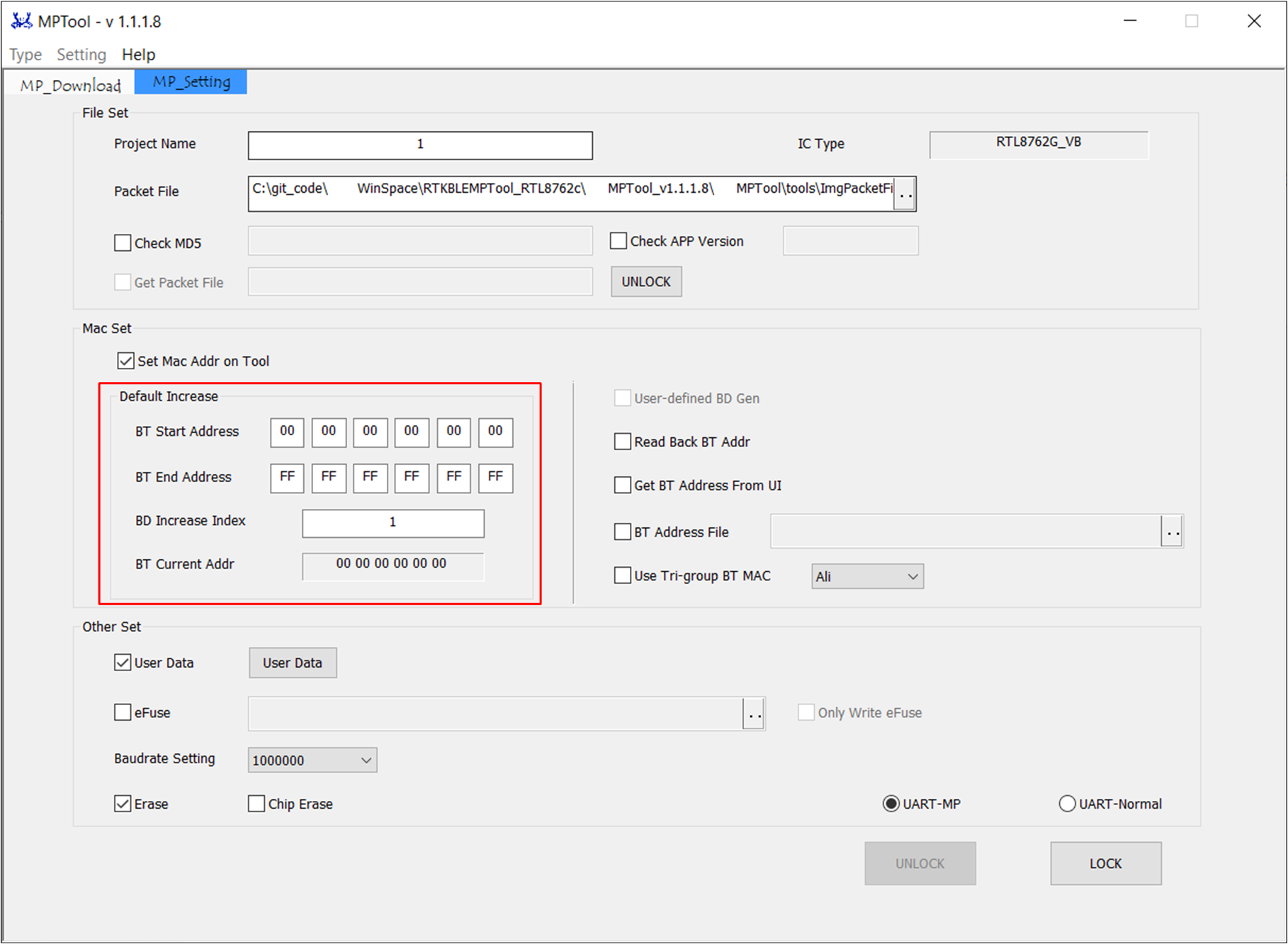
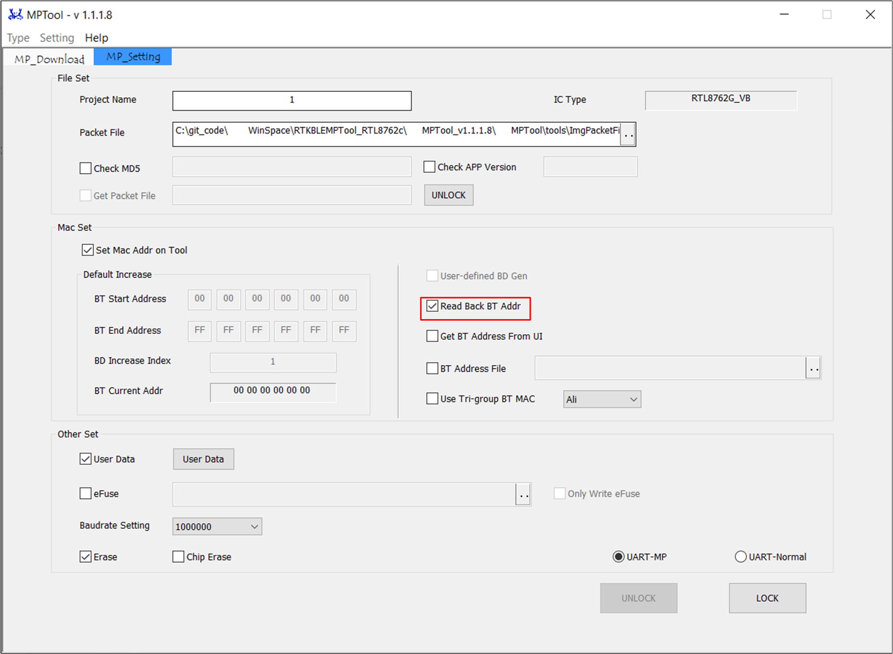
In the [MP_Setting] interface, uncheck other options. Set the starting and ending Bluetooth addresses, and also set the Bluetooth address increment index (ranging from 0 to 99).
This way, the MP Tool will automatically increase the Bluetooth address during programming based on the configured options. It is as shown in the figure below.
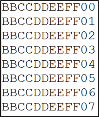
MP Tool can also obtain Bluetooth addresses from a txt file. This txt file is produced by the user. After MP Tool finishes programming a Bluetooth address, it will remove the corresponding address from the txt file.
The BT address's format in txt file is as shown in the figure below.
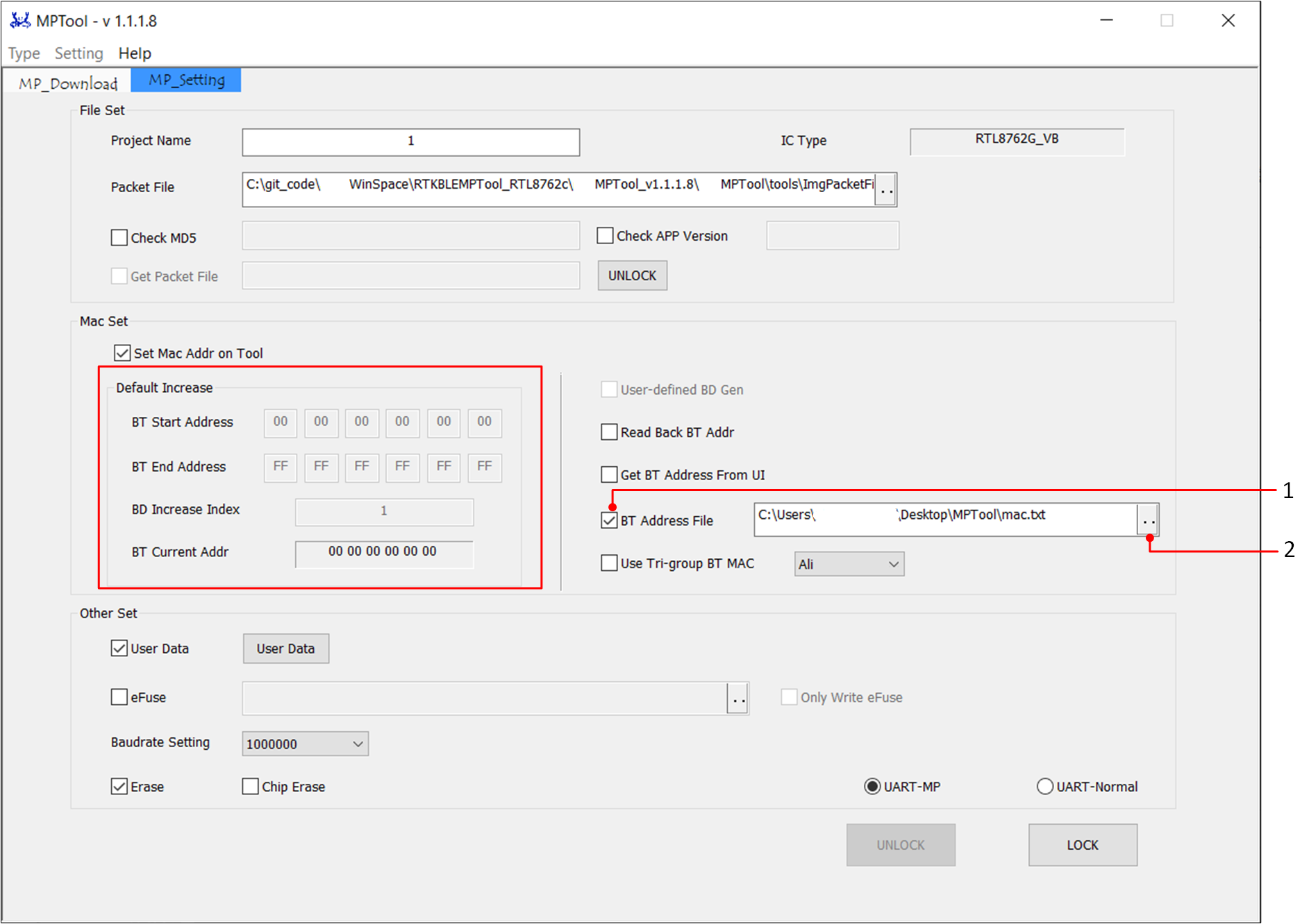
To enable the functionality of obtaining Bluetooth addresses from a file, users need to check the BT Address File on [MP_Setting] page.
Additionally, import the Bluetooth address txt file into the path field, as shown in the figure below.
Note
Obtaining Bluetooth addresses from a file takes priority over MP Tool's automatic generation of Bluetooth addresses. When the BT Address File is selected, MP Tool will disable the automatic generation of Bluetooth addresses.
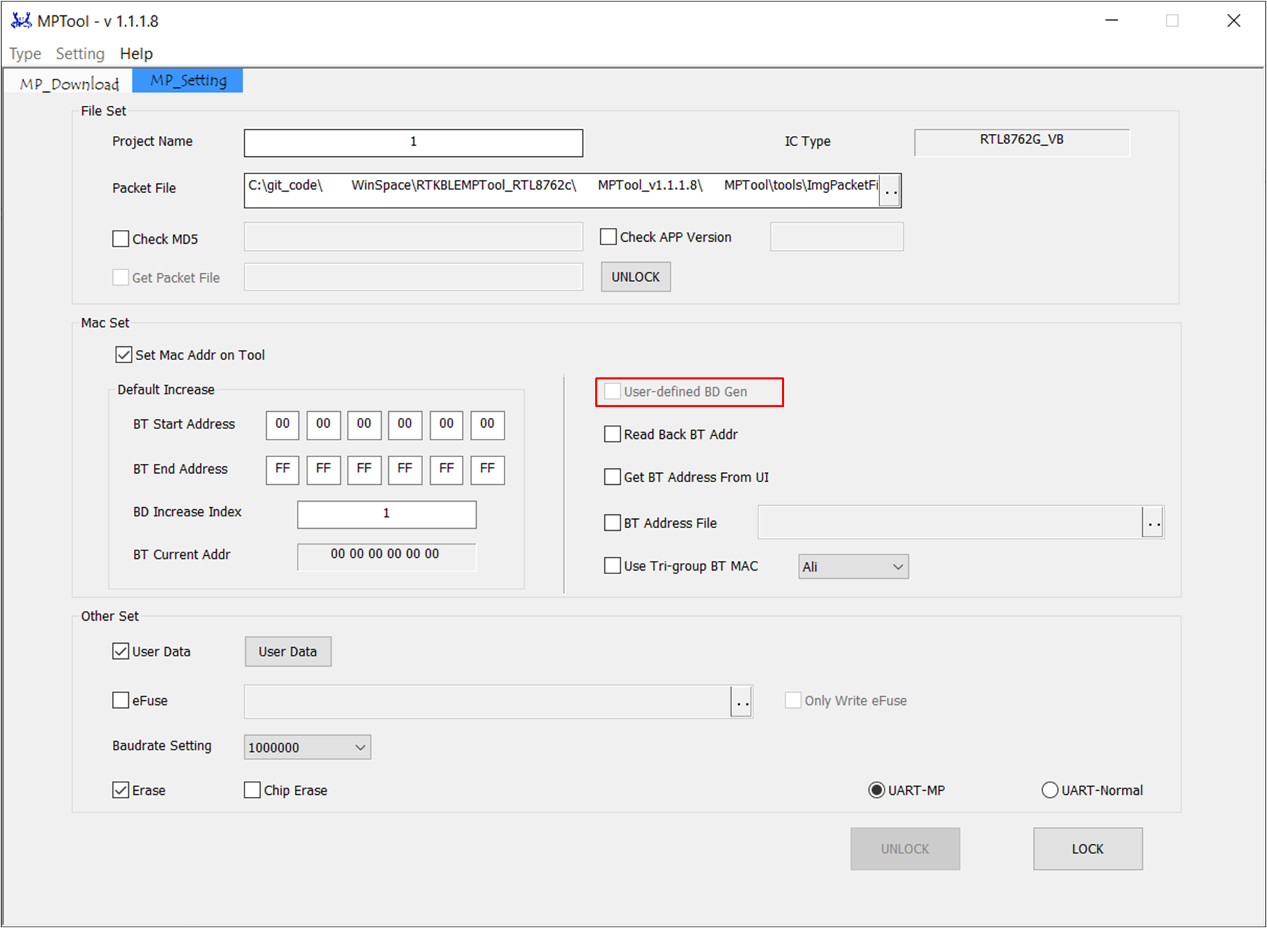
To enable the custom Bluetooth address generation functionality, the user needs to provide a DLL or lib file for generating the Bluetooth addresses. MP Tool will then call the relevant API in order to generate the Bluetooth addresses required for programming.
To use this feature, you need to check the User-defined BD Gen, as shown in the figure below.
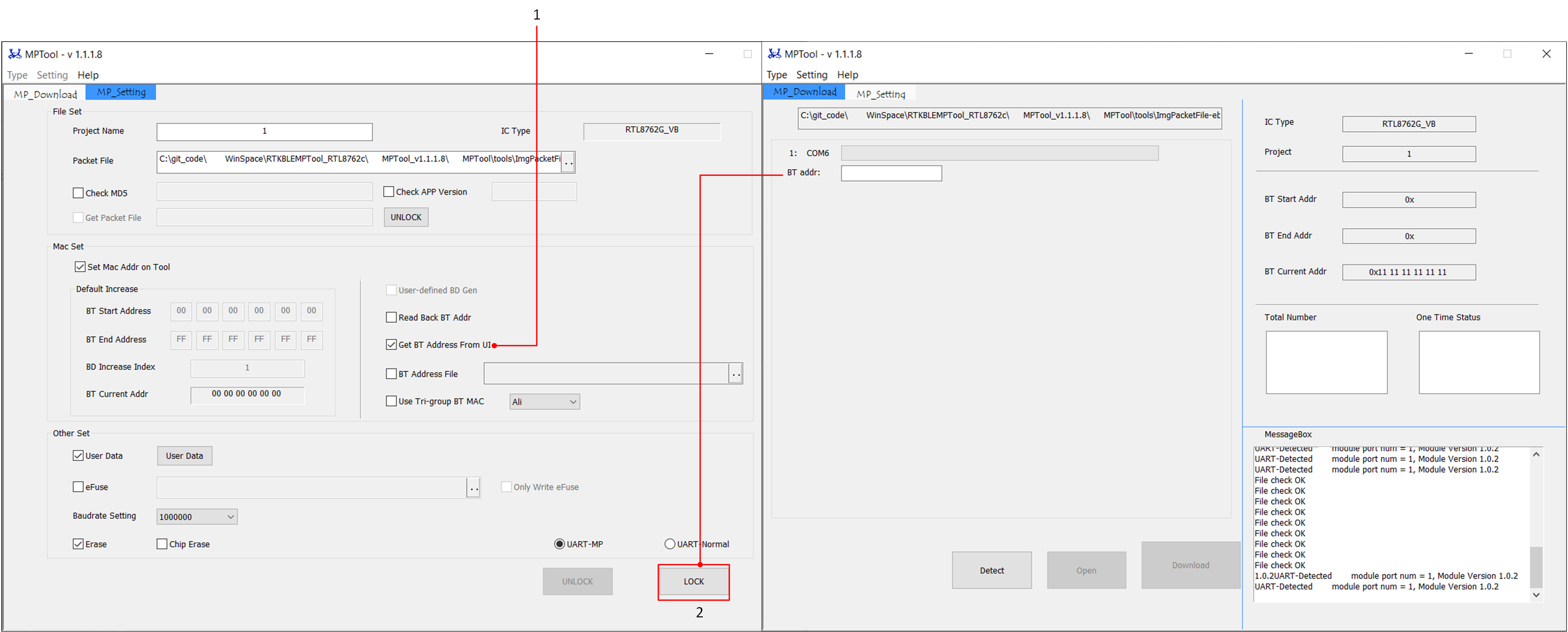
The functionality of obtaining Bluetooth addresses from the interface allows users to enter the corresponding Bluetooth address for each COM port on the MP Download page during production.
To use this feature, users need to check the Get BT Address from UI then click LOCK on [MP_Setting] page.
The Bluetooth address field in [MP_Download] will become editable, as shown in the figure below.
The read back mac feature allows users to read the existing Bluetooth address from the flash memory and then write it back to the flash memory, thus keeping the Bluetooth address unchanged in the flash.
Note
To use this feature, it is necessary to ensure that there is a Bluetooth address present in the flash memory, and there is a Mac configuration item in configfile.
In the Debug Mode, if the BT Address option is not checked in the configfile but this feature is chosen, the read BT address will be appended to the config data.
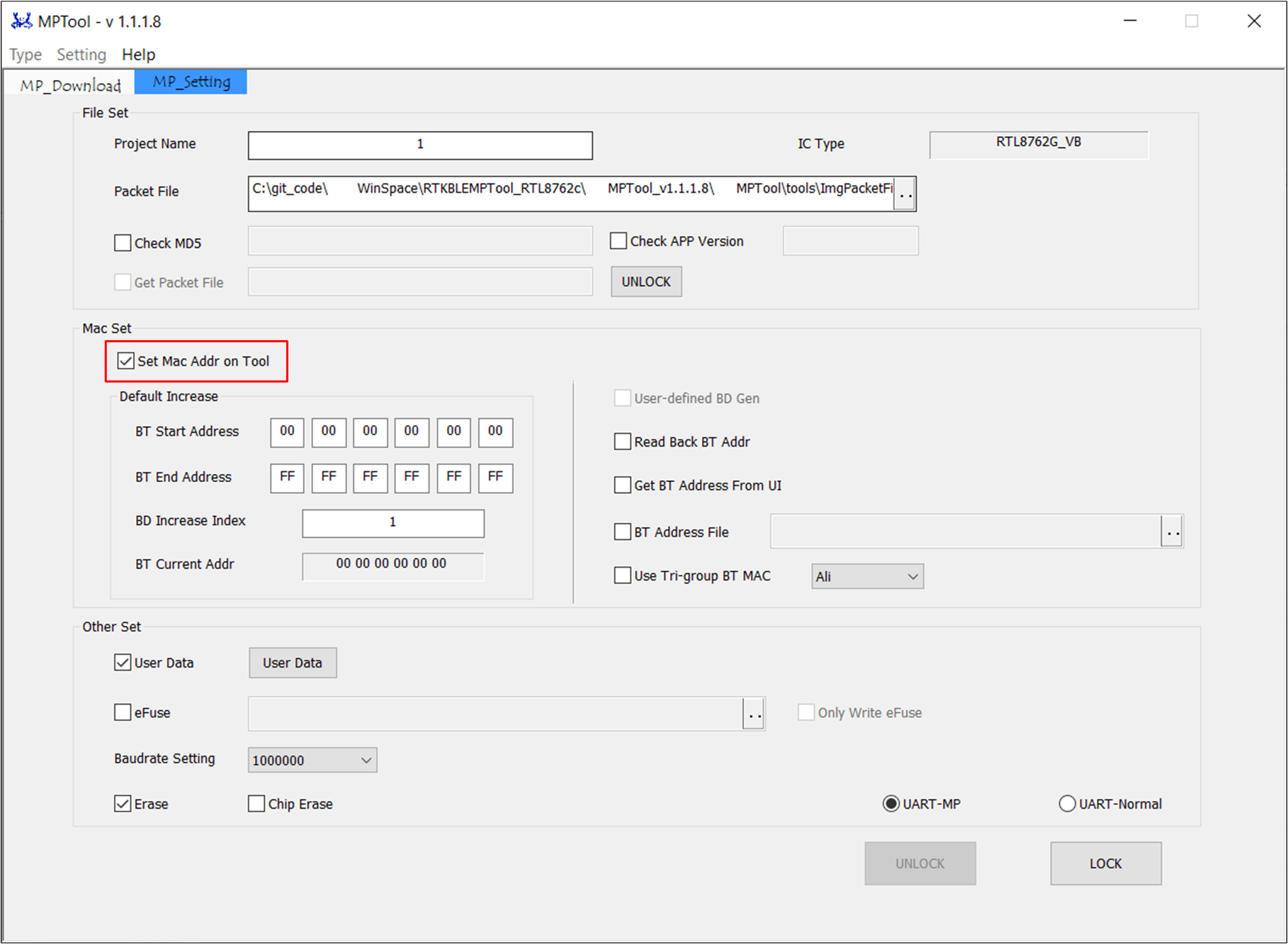
In the MP Mode, if Set Mac Addr on Tool is checked, but the Bluetooth address is not checked in the configfile, the tool will not allow locking.
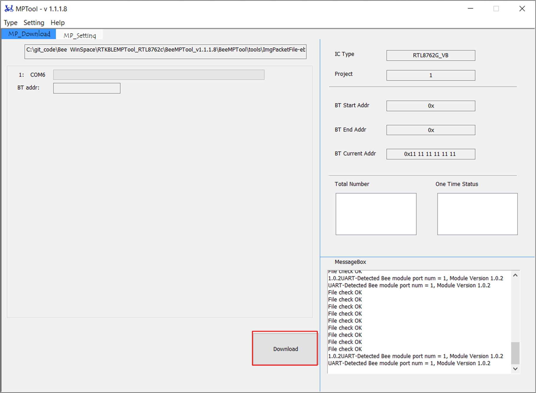
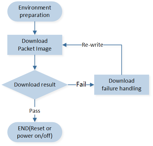
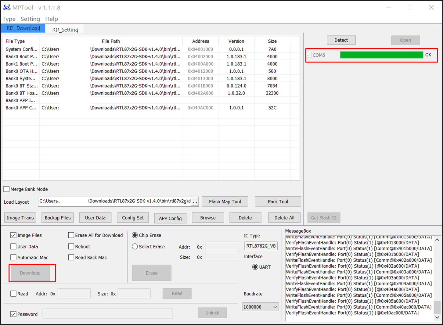
On the factory side, operators only need to click the Download button to achieve the one-click programming function, as shown in the figure below.
The MP Tool will automatically save the programming information in the Log folder within the program directory.
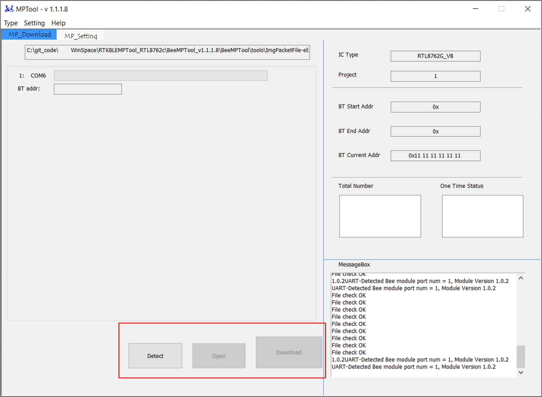
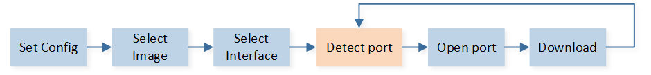
If the One Button Download option is unchecked in the settings menu, the MP_Download interface will display additional Detect and Open buttons.
The operating steps at this time are as follows: Detect → Open → Download. As shown in the figure below, it is not One Button download. Usually, it is not advisable to uncheck One-click Download.
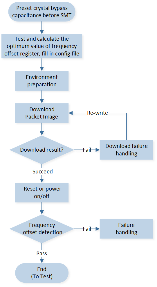
As shown in the figure below, it is necessary to adjust frequency offset of crystal first. Users can calibrate the optimum value of crystal capacitance and frequency offset calibration capacitance of internal chips before Mass production.
Users need to preset crystal bypass capacitance before SMT. The crystal needs to be in the same batch to ensure that the characteristics of the crystal stay the same. Otherwise, the frequency offset can't be calibrated to target range.
In Debug Mode, MP Tool supports setting various parameters in the Config Set options and generating the corresponding Configbin file, which is saved in the Config File folder. This Config File can be directly downloaded to flash in Debug mode or used to compose package files.
Additionally, the [load bin] function supports reading back the configuration options from the previous Config File.
Note
For configuration of the config file, users can contact Realtek to obtain it or configure it themselves after understanding the configuration options.
When configuring the config file on your own, if an item is not checked, the config configuration will be set according to the patch.
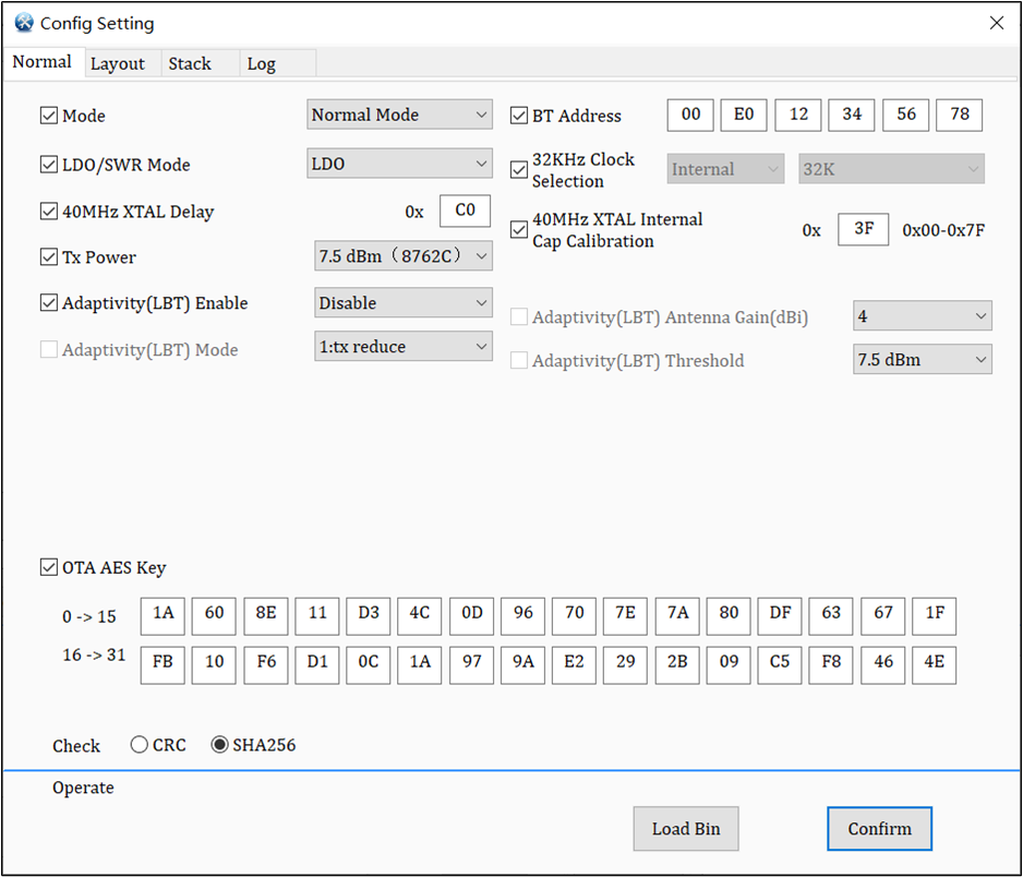
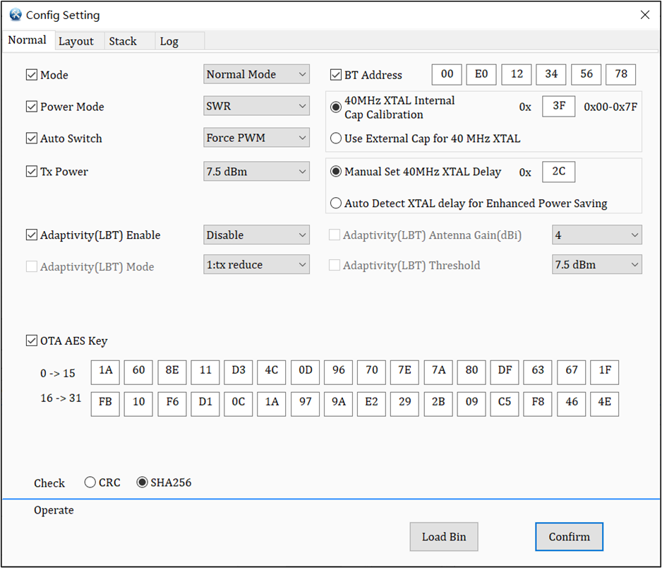
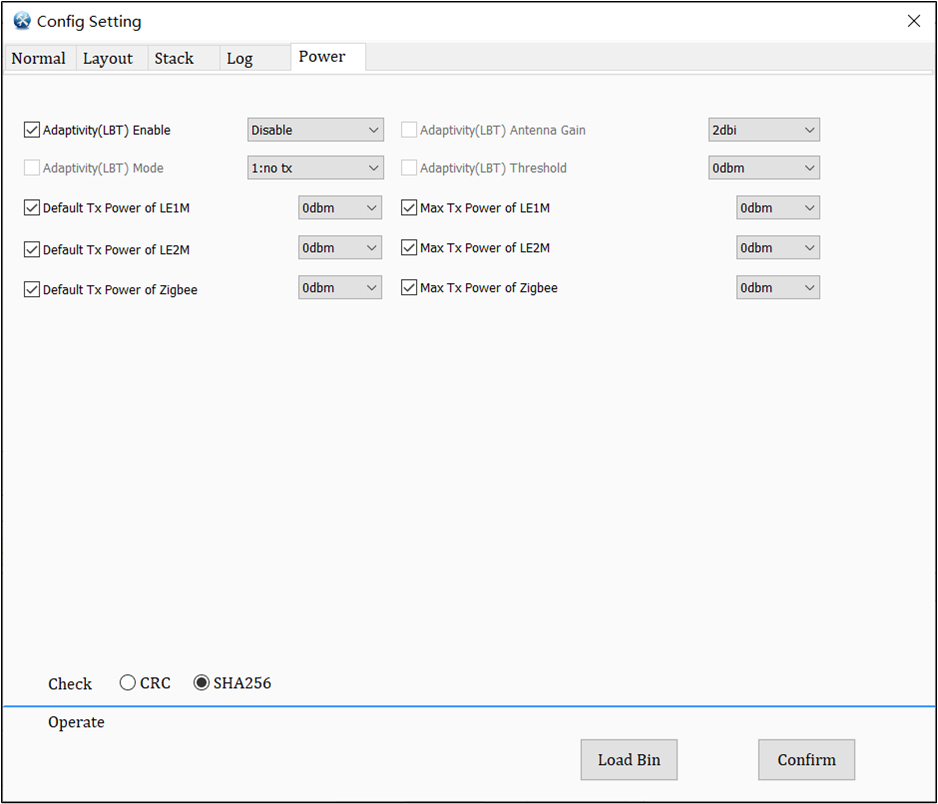
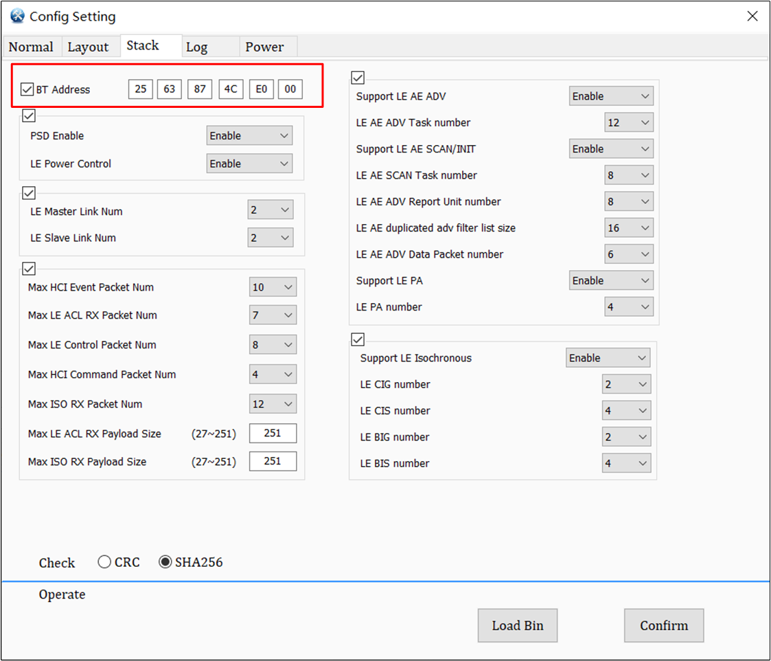
The Config settings interface includes four configuration pages. Users can choose configurations based on their actual needs. Typically, focusing on the relevant config items on the Normal page is sufficient to meet the requirements.
Mode selection has MP/RF test Mode and Normal Mode to determine the working mode of the IC (default is Normal Mode).
Please note that Mode must be selected correctly, otherwise the IC behavior may not be correct.
Normal Mode: The interaction with the app can be achieved.
MP/RF test mode: HCI is available. Generally used for program downloading and RF performance testing.
BT Address
Used to set BT MAC address. This is checked by default. If users want to use the Automatic BT Address function, users must select this check box when configuring ConfigFile. This item must also be checked when using tools to update Mac.
LDO/SWR Mode
The LDO/SWR Mode option can select LDO or SWR mode. The LDO consumes power, but it can save the use of inductors. The SW (Single Wire Return) MODE can save power, but it requires the use of multiple inductors.
Power mode must be paired with the correct peripheral circuitry, otherwise the IC behavior may be incorrect or even damage the IC.
32KHz Clock Selection
Used to select internal 32K or external 32K.
40MHz XTAL Delay
Used to set the IC start-up waiting time. It needs to be longer than the start-up time of XTAL to ensure the normal boot of IC, the default value of RTL8762C is 0xC0.
40MHz XTAL Internal
Cap Calibration
When there is no external load capacitor CLoad in 40MHz XTAL, check the 40MHz XTAL internal cap calibration option to turn on the IC internal capacitance adjustment to realize frequency offset calibration. The setting range is 0x00 ~ 0x7F, and the default value is 0x3F.
0x7F means the internal matching capacitor is all off, 0x00 means the internal matching capacitor is all on, increase the matching capacitor, the actual frequency will be lowered, i.e., the frequency deviation will be shifted to the negative direction, for more detailed introduction, please refer to Hardware instruction.
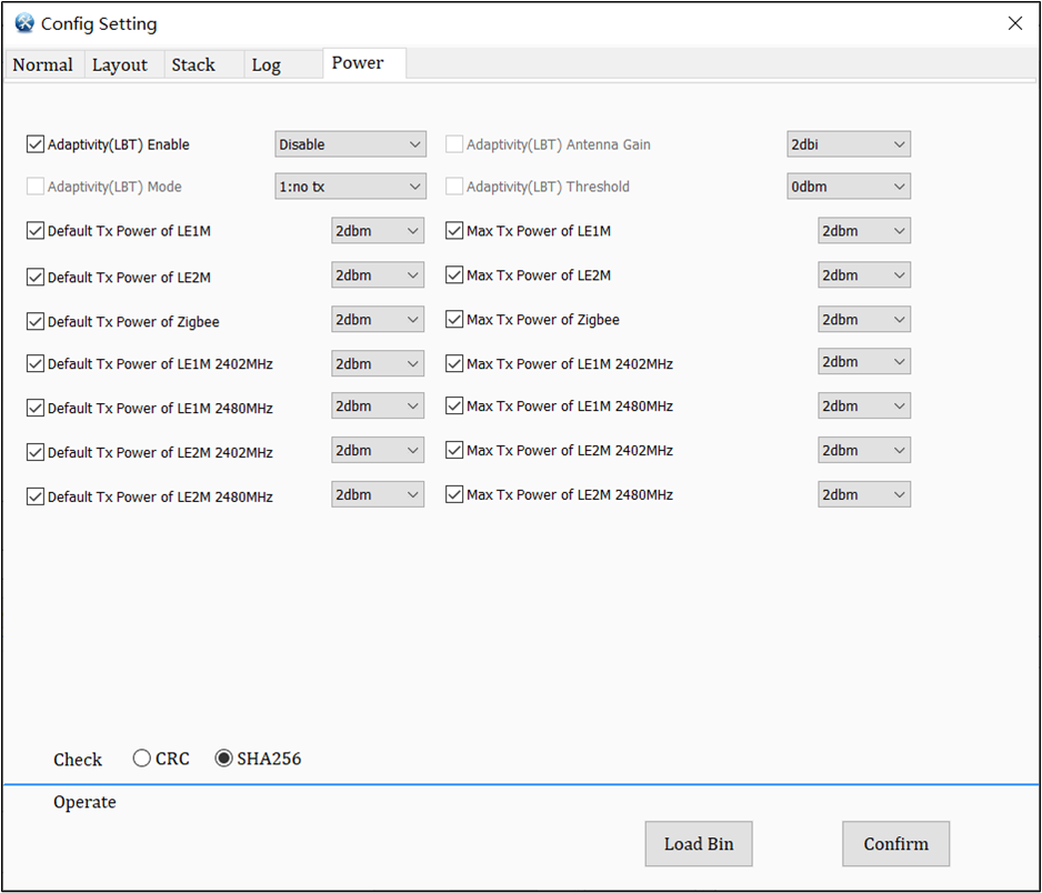
Tx Power
Used to set the power of TX, there are -20dBm, 0dBm, 3dBm, 4dBm, 7.5dBm. It is suggested that the set value should not exceed the limit of the IC's own tx power.
Adaptivity (LBT) Enable
LBT is used for anti-interference settings. This item is the enablement of the Adaptivity function. Only after this item is enabled, other subsequent LBT settings can take effect.
Adaptivity (LBT) Mode
There are two modes when LBT is enabled.
no tx: no more tx.
reduce tx: reduce power to do tx.
Adaptivity (LBT) Antenna Gain
Actual antenna gain of product, with a step size of 0.5db.
Adaptivity (LBT) Threshold
Used to set the threshold for LBT enablement. LBT will be triggered only when target power + gain > threshold.
OTA AES Key
Used to set whether the OTA needs to be encrypted for transmission, and the AES Key used for encrypted transmission can be input by the users according to requirements.
Check
The check mode that can be selected is CRC or SHA256. (Because the config file data can be modified directly, and the platform will skip the verification of this file, CRC or SHA256 can be selected arbitrarily)
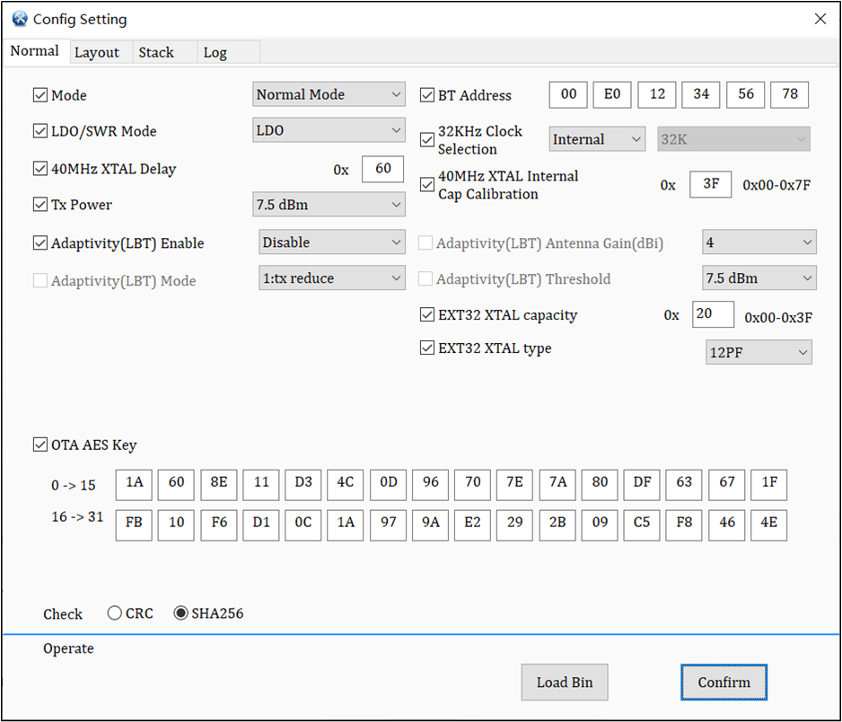
Mode selection has MP/RF test Mode and Normal Mode to determine the working mode of the IC (default is Normal Mode).
Please note that Mode must be selected correctly, otherwise the IC behavior may not be correct.
Normal Mode: The interaction with the app can be achieved.
MP/RF test mode: HCI is available. Generally used for program downloading and RF performance testing.
BT Address
Used to set BT MAC address. This is checked by default. If users want to use the Automatic BT Address function, users must select this check box when configuring ConfigFile. This item must also be checked when using tools to update Mac.
LDO/SWR Mode
The LDO/SWR Mode option can select LDO or SWR mode. The LDO consumes power, but it can save the use of inductors. The SW (Single Wire Return) MODE can save power, but it requires the use of multiple inductors.
Power mode must be paired with the correct peripheral circuitry, otherwise the IC behavior may be incorrect or even damage the IC.
32KHz Clock
Selection
Used to select internal 32K or external 32K.
40MHz XTAL Delay
Used to set the IC start-up waiting time. It needs to be longer than the start-up time of XTAL to ensure the normal boot of IC, the default value of RTL8762D is 0x60.
40MHz XTAL Internal
Cap Calibration
When there is no external load capacitor CLoad in 40MHz XTAL, check the 40MHz XTAL internal cap calibration option to turn on the IC internal capacitance adjustment to realize frequency offset calibration. The setting range is 0x00 ~ 0x7F, and the default value is 0x3F.
0x7F means the internal matching capacitor is all off, 0x00 means the internal matching capacitor is all on, increase the matching capacitor, the actual frequency will be lowered, i.e., the frequency deviation will be shifted to the negative direction, for more detailed introduction, please refer to Hardware instruction.
Tx Power
Used to set the power of TX, there are -20dBm, 0dBm, 3dBm, 4dBm, 7.5dBm. It is suggested that the set value should not exceed the limit of the IC's own tx power.
Adaptivity (LBT) Enable
LBT is used for anti-interference settings. This item is the enablement of the Adaptivity function. Only after this item is enabled, other subsequent LBT settings can take effect.
Adaptivity (LBT) Mode
There are two modes when LBT is enabled.
no tx: no more tx.
reduce tx: reduce power to do tx.
Adaptivity (LBT) Antenna Gain
Actual antenna gain of product, with a step size of 0.5db.
Adaptivity (LBT) Threshold
Used to set the threshold for LBT enablement. LBT will be triggered only when target power + gain > threshold.
EXT32K XTAL Capacity
Adjust the internal capacitance of the IC to achieve frequency offset calibration. Please note that if external matching capacitors are not used, it can only support a 32.768K XTAL with a maximum CL=8pF.
EXT32K XTAL type
Set the corresponding Config according to EXT32.768K XTAL CL.
OTA AES Key
Used to set whether the OTA needs to be encrypted for transmission, and the AES Key used for encrypted transmission can be input by the users according to requirements.
Check
The check mode that can be selected is CRC or SHA256. (Because the config file data can be modified directly, and the platform will skip the verification of this file, CRC or SHA256 can be selected arbitrarily)
Mode selection has MP/RF test Mode and Normal Mode to determine the working mode of the IC (default is Normal Mode).
Please note that Mode must be selected correctly, otherwise the IC behavior may not be correct.
Normal Mode: The interaction with the app can be achieved.
MP/RF test mode: HCI is available. Generally used for program downloading and RF performance testing.
BT Address
Used to set BT MAC address. This is checked by default. If users want to use the Automatic BT Address function, users must select this check box when configuring ConfigFile. This item must also be checked when using tools to update Mac.
Power Mode
The Power Mode option can select LDO or SWR mode (the default is fix pwm of RTL8762E'patch). The LDO consumes power, but it can save the use of inductors. The SW (Single Wire Return) MODE can save power,
but it requires the use of multiple inductors. When select SWR mode in RTL8762E, users can choose Auto Switch.
Power mode must be paired with the correct peripheral circuitry, otherwise the IC behavior may be incorrect or even damage the IC.
40MHz XTAL Internal
Cap Calibration
When there is no external load capacitor CLoad in 40MHz XTAL, check the 40MHz XTAL internal cap calibration option to turn on the IC internal capacitance adjustment to realize frequency offset calibration. The setting range is 0x00 ~ 0x7F, and the default value is 0x3F.
0x7F means the internal matching capacitor is all off, 0x00 means the internal matching capacitor is all on, increase the matching capacitor, the actual frequency will be lowered, i.e., the frequency deviation will be shifted to the negative direction, for more detailed introduction, please refer to Hardware instruction.
Use External Cap for 40MHz XTAL
When 40MHz XTAL adjusts the frequency offset through the external load capacitance CLoad, check use external cap for 40MHz XTAL (RTL8762E only) to turn off the internal capacitance, between this option and 40MHz XTAL internal cap calibration, users can check only one at the same time.
Manual Set 40MHz XTAL Delay
Used to set the IC start-up waiting time. It needs to be longer than the start-up time of XTAL to ensure the normal boot of IC, the default value of RTL8762E is 0x2C.
Auto Detect XTAL delay For Enhanced Power Saving
Check Auto Detect XTAL delay For Enhanced Power Saving to enable the automatic detection function of crystal oscillator starting time, there is no need to manually set the value of 40MHz XTAL delay, IC will automatically detect and fill in appropriate values to minimize power consumption.
Between this option and Manual Set 40MHz XTAL Delay, users can check only one at the same time. In addition, please ensure that the selected XTAL meets the requirements before opening this function, refer to RTL8762E Hardware Instruction section 4.2.2 in HDK for specific spec and crystal spec & QVL in RTL8762E_Reference_Rbom.
Tx Power
Used to set the power of TX, there are -20dBm, 0dBm, 3dBm, 4dBm, 7.5dBm. It is suggested that the set value should not exceed the limit of the IC's own tx power.
Adaptivity (LBT) Enable
LBT is used for anti-interference settings. This item is the enablement of the Adaptivity function. Only after this item is enabled, other subsequent LBT settings can take effect.
Adaptivity (LBT) Mode
There are two modes when LBT is enabled.
no tx: no more tx.
reduce tx: reduce power to do tx.
Adaptivity (LBT) Antenna Gain
Actual antenna gain of product, with a step size of 0.5db.
Adaptivity (LBT) Threshold
Used to set the threshold for LBT enablement. LBT will be triggered only when target power + gain > threshold.
OTA AES Key
Used to set whether the OTA needs to be encrypted for transmission, and the AES Key used for encrypted transmission can be input by the users according to requirements.
Check
The check mode that can be selected is CRC or SHA256. (Because the config file data can be modified directly, and the platform will skip the verification of this file, CRC or SHA256 can be selected arbitrarily)
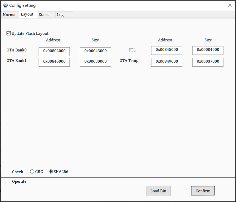
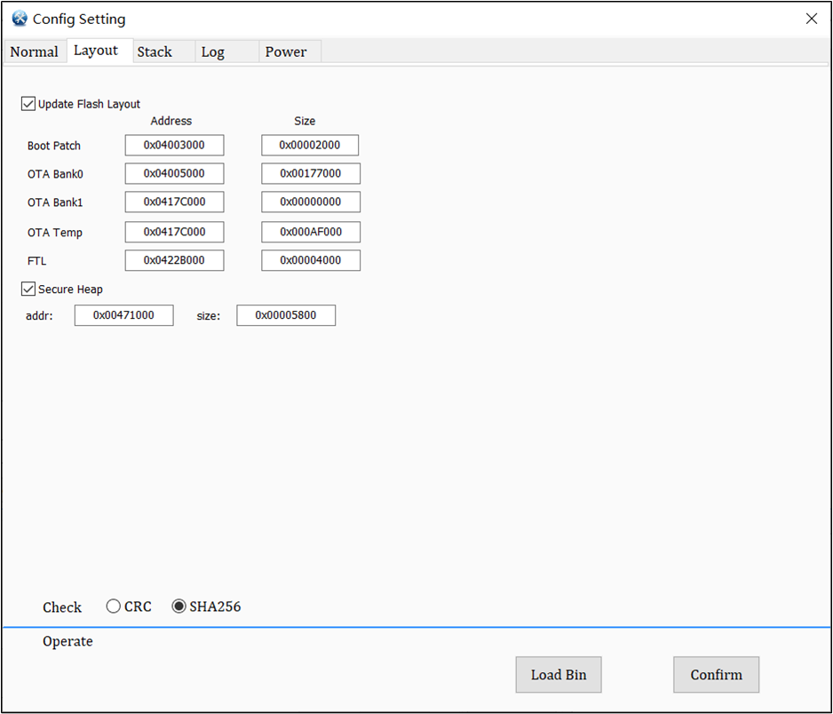
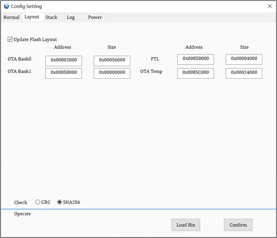
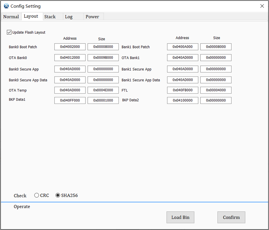
Config Set-Layout
If flashmap.ini has been loaded, the area address planned in the file will be displayed on the [Layout] page, and the address bar will be locked; If the flashmap.ini is not loaded, users can manually plan the download area.
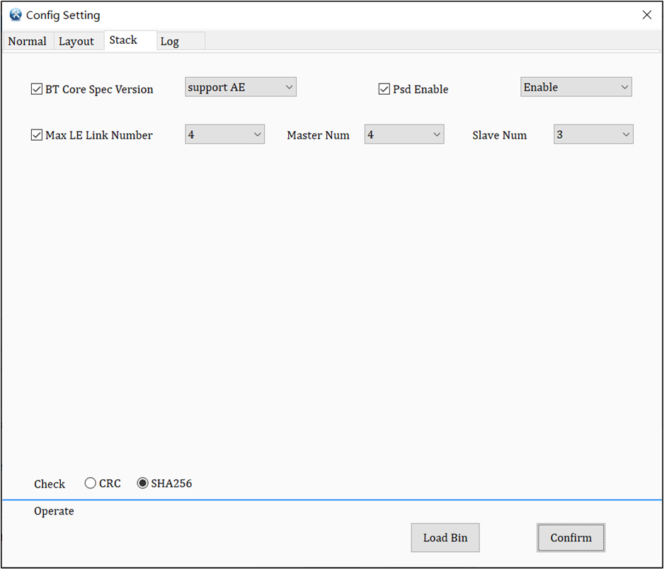
Used to control whether AE and other combined functions are selected. Users can save heap size when don't use it. Users can consult Realtek for specific use.
Psd Enable
Used for energy monitoring of channel. Enable enables this function.
Max LE Link Number
The maximum number of BLE links supported. Master Num and Slave Num are the number of links supported as master and slave respectively. Refer to LE Host.
Used to control whether AE and other combined functions are selected. Users can save heap size when don't use it. Users can consult Realtek for specific use.
Psd Enable
Used for energy monitoring of channel. Enable enables this function.
Max LE Link Number
The maximum number of BLE links supported. RTL8762E only needs to set the master and slave. Refer to LE Host.
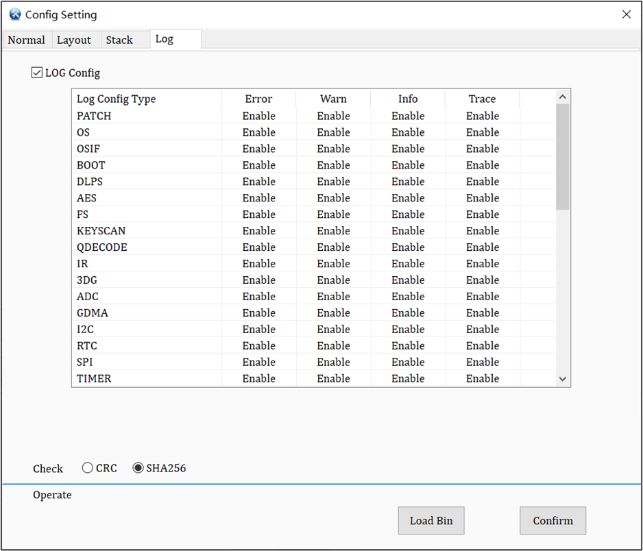
Config Set-Log
The log setting interface of config is used for some switches to output log. Enable and Disable can control whether to output a log.
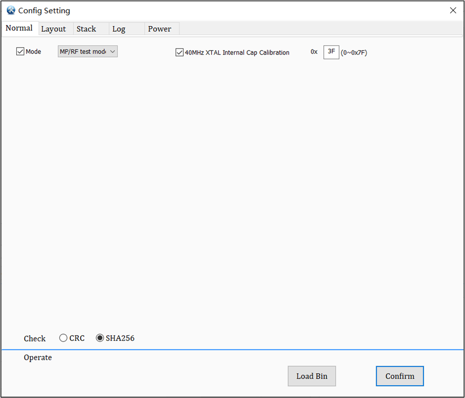
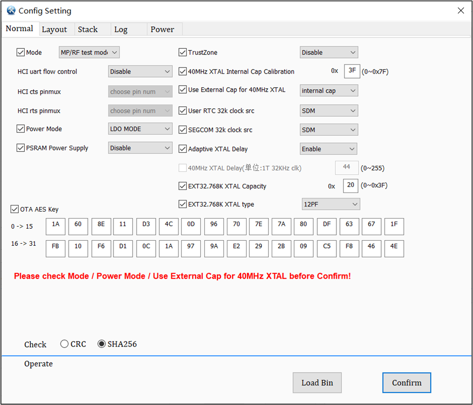
The Config settings interface includes four configuration pages. Users can choose configurations based on their actual needs. Typically, focusing on the relevant config items on the Normal page is sufficient to meet the requirements.
MPTool_v1.1.1.6 and later versions, when selecting ICs RTL 8762G_VB/ 8771GUV/ 8772GWP/ 8777G/ 8772G, need to open port first before accessing [Config Setting].
Mode selection includes MP/RF test Mode and Normal Mode to determine the working mode of the IC (default is Normal Mode).
Please note that Mode must be selected correctly, otherwise the IC behavior may not be correct.
Normal Mode: The interaction with the app can be achieved.
MP/RF test mode: HCI is available. Generally used for program downloading and RF performance testing.
40MHz XTAL Internal Cap Calibration
When there is no external load capacitor CLoadfor the 40MHz XTAL, the option 40MHz XTAL Internal Cap Calibration needs to be selected to enable internal capacitor adjustment in order to achieve frequency offset calibration.
The setting range is 0x00 to 0x7F, with the default value being 0x3F. 0x7F indicates that all internal matching capacitors are turned off, while 0x00 indicates that all internal matching capacitors are turned on.
Increasing the matching capacitance will lower the actual frequency, causing a frequency offset in the negative direction. For a more detailed explanation, please refer to Hardware Instruction.
Check
The check mode that can be selected is CRC or SHA256. (Because the config file data can be modified directly, and the platform will skip the verification of this file, CRC or SHA256 can be selected arbitrarily)
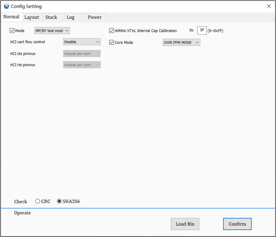
Mode selection includes MP/RF test Mode and Normal Mode to determine the working mode of the IC (default is Normal Mode).
Please note that Mode must be selected correctly, otherwise the IC behavior may not be correct.
Normal Mode: The interaction with the app can be achieved.
MP/RF test mode: HCI is available. Generally used for program downloading and RF performance testing.
HCI uart flow control
To determine whether the IC should enable UART flow control functionality in HCI mode.
HCI cts/rts pinmux
In the UART flow control mechanism, the selection of corresponding pins should not choose the same pins simultaneously.
40MHz XTAL Internal Cap Calibration
When there is no external load capacitor CLoadfor the 40MHz XTAL, the option 40MHz XTAL Internal Cap Calibration needs to be selected to enable internal capacitor adjustment in order to achieve frequency offset calibration.
The setting range is 0x00 to 0x7F, with the default value being 0x3F. 0x7F indicates that all internal matching capacitors are turned off, while 0x00 indicates that all internal matching capacitors are turned on.
Increasing the matching capacitance will lower the actual frequency, causing a frequency offset in the negative direction. For a more detailed explanation, please refer to Hardware Instruction.
Core Mode
The LDO Mode consumes power, but it can save the use of inductors. The SWR Mode can save power, but it requires the use of multiple inductors. For RTL8762G_VB, the choice between SWR_PWM_MODE and SWR_AUTO_MODE depends on whether the PCB is a single-sided board or not. If it is a single-sided board, it is recommended to choose SWR_PWM_MODE.
LDO_MODE: In this mode, the external power inductor connected between LX and VDDCORE is not required. By default, the core_mode of the device is LDO_MODE.
SWR_PWM_MODE: In this mode, the switching regulator only operates in PWM mode when the system is active. This mode sacrifices the efficiency of the buck conversion when the current loading of the system is light loading, but enhances the rejection of the switching noise from power and ground with higher resistance. This mode is suitable for the single-layer PCB design that always has poor ground and power plan in the PCB design.
SWR_AUTO_MODE: In this mode, the switching regulator automatically switches between PFM mode and PWM mode according to the current loading of the system to achieve the best performance and efficiency of buck conversion.
Check
The check mode that can be selected is CRC or SHA256. (Because the config file data can be modified directly, and the platform will skip the verification of this file, CRC or SHA256 can be selected arbitrarily)
Mode selection includes MP/RF test Mode and Normal Mode to determine the working mode of the IC (default is Normal Mode).
Please note that Mode must be selected correctly, otherwise the IC behavior may not be correct.
Normal Mode: The interaction with the app can be achieved.
MP/RF test mode: HCI is available. Generally used for program downloading and RF performance testing.
HCI uart flow control
To determine whether the IC should enable UART flow control functionality in HCI mode.
HCI cts/rts pinmux
In the UART flow control mechanism, the selection of corresponding pins should not choose the same pins simultaneously.
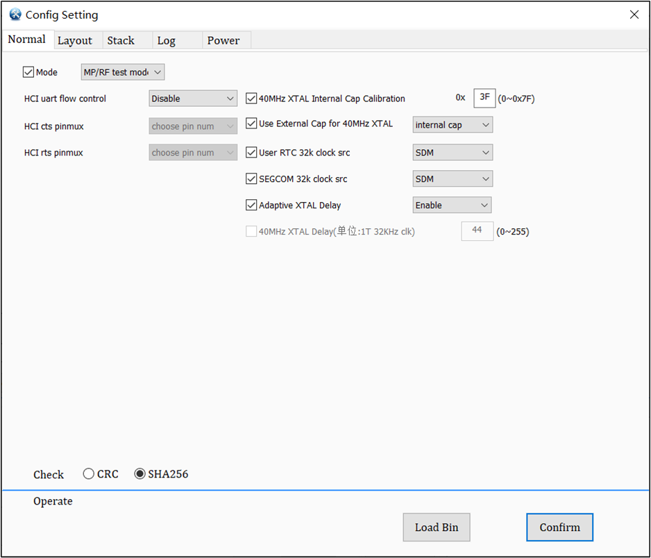
40MHz XTAL Internal Cap Calibration
When there is no external load capacitor CLoadfor the 40MHz XTAL, the option 40MHz XTAL Internal Cap Calibration needs to be selected to enable internal capacitor adjustment in order to achieve frequency offset calibration.
The setting range is 0x00 to 0x7F, with the default value being 0x3F. 0x7F indicates that all internal matching capacitors are turned off, while 0x00 indicates that all internal matching capacitors are turned on.
Increasing the matching capacitance will lower the actual frequency, causing a frequency offset in the negative direction. For a more detailed explanation, please refer to Hardware Instruction.
Use External Cap for 40MHz XTAL
Select whether the 40M XTAL uses an external load capacitor to adjust the frequency bias, and if external cap is selected, the internal load capacitor will be turned off.
User RTC 32k clock src/SEGCOM 32k clock src
32k clock src of user rtc or segcom; SDM is the internal 32k clock src using OSC128KHz as source; EXT32 XTAL is an external 32k clock src, which is used by users and more accurate than SDM usually, but SDM can save more power.
Adaptive XTAL Delay
Enable automatic detection of crystal oscillator start-up time, eliminating the need for manual setting of the 40MHz XTAL Delay value. The IC will automatically detect and fill in the appropriate value to maximize power savings.
40MHz XTAL Delay
The IC start-up waiting time should be set to a value greater than the start-up time of the crystal oscillator (XTAL) to ensure proper booting of the IC. The setting range is 0 ~ 255, and the default value is 44. For a more detailed explanation, please refer to Hardware Instruction.
Check
The check mode that can be selected is CRC or SHA256. (Because the config file data can be modified directly, and the platform will skip the verification of this file, CRC or SHA256 can be selected arbitrarily)
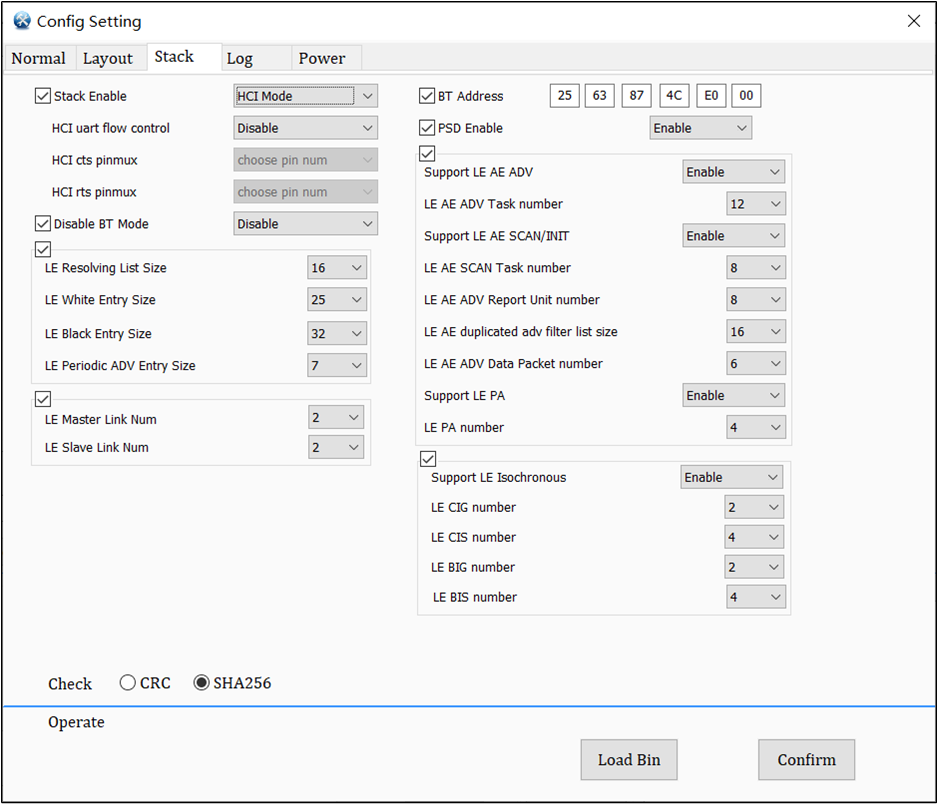
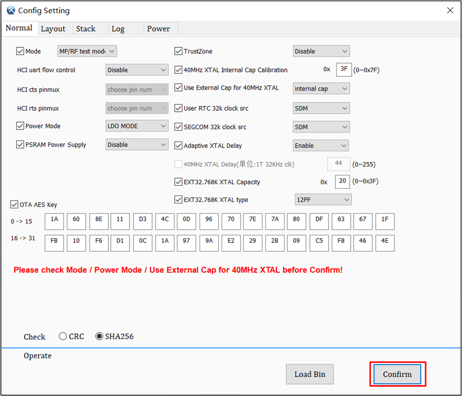
RTL8762G_VB/8771GUV/8772GWP/8777G/8772G Config Normal Setting Interface
Mode selection includes MP/RF test Mode and Normal Mode to determine the working mode of the IC (default is Normal Mode).
Please note that Mode must be selected correctly, otherwise the IC behavior may not be correct.
Normal Mode: The interaction with the app can be achieved.
MP/RF test mode: HCI is available. Generally used for program downloading and RF performance testing.
HCI uart flow control
To determine whether the IC should enable UART flow control functionality in HCI mode.
HCI cts/rts pinmux
In the UART flow control mechanism, the selection of corresponding pins should not choose the same pins simultaneously.
Power Mode
The LDO Mode consumes power, but it can save the use of inductors. The SWR Mode can save power, but it requires the use of multiple inductors. For RTL8762G_VB, the choice between SWR_PWM_MODE and SWR_AUTO_MODE depends on whether the PCB is a single-sided board or not. If it is a single-sided board, it is recommended to choose SWR_PWM_MODE.
LDO_MODE: In this mode, the external power inductor connected between LX and VDDCORE is not required. By default, the core_mode of the device is LDO_MODE.
SWR_PWM_MODE: In this mode, the switching regulator only operates in PWM mode when the system is active. This mode sacrifices the efficiency of the buck conversion when the current loading of the system is light loading, but enhances the rejection of the switching noise from power and ground with higher resistance. This mode is suitable for the single-layer PCB design that always has poor ground and power plan in the PCB design.
SWR_AUTO_MODE: In this mode, the switching regulator automatically switches between PFM mode and PWM mode according to the current loading of the system to achieve the best performance and efficiency of buck conversion.
PSRAM Power Supply
The default is disabled, which will power down the PSRAM in Active and DLPS mode to save power. If PSRAM is used in the SDK, it needs to be enabled.
TrustZone
Allows users to partition the memory into secure and non-secure regions, disabled by default.
40MHz XTAL Internal Cap Calibration
When there is no external load capacitor CLoadfor the 40MHz XTAL, the option 40MHz XTAL Internal Cap Calibration needs to be selected to enable internal capacitor adjustment in order to achieve frequency offset calibration.
The setting range is 0x00 to 0x7F, with the default value being 0x3F. 0x7F indicates that all internal matching capacitors are turned off, while 0x00 indicates that all internal matching capacitors are turned on.
Increasing the matching capacitance will lower the actual frequency, causing a frequency offset in the negative direction. For a more detailed explanation, please refer to Hardware Instruction.
User RTC 32k clock src/SEGCOM 32k clock src
32k clock src of user rtc or segcom; SDM is the internal 32k clock src using OSC128KHz as source; EXT32 XTAL is an external 32k clock src, which is used by users and more accurate than SDM usually, but SDM can save more power.
Use External Cap for 40MHz XTAL
Select whether the 40M XTAL uses an external load capacitor to adjust the frequency bias, and if external cap is selected, the internal load capacitor will be turned off.
Adaptive XTAL Delay
Enable automatic detection of crystal oscillator start-up time, eliminating the need for manual setting of the 40MHz XTAL Delay value. The IC will automatically detect and fill in the appropriate value to maximize power savings.
40MHz XTAL Delay
The IC start-up waiting time should be set to a value greater than the start-up time of the crystal oscillator (XTAL) to ensure proper booting of the IC. The setting range is 0 ~ 255, and the default value is 44. For a more detailed explanation, please refer to Hardware Instruction.
EXT32.768K XTAL Capacity
Adjust the internal capacitor of the IC to achieve frequency offset calibration. Please note that if external matching capacitors are not used, the maximum supported load capacitance is 8pF for the 32.768K XTAL.
EXT32.768K XTAL type
Make the corresponding config settings based on the EXT32.768K XTAL CL.
OTA AES Key
Used to set whether the OTA needs to be encrypted for transmission, and the AES Key used for encrypted transmission can be input by the users according to requirements.
Check
The check mode that can be selected is CRC or SHA256. (Because the config file data can be modified directly, and the platform will skip the verification of this file, CRC or SHA256 can be selected arbitrarily)
Config Set-Layout
If the flashmap.ini file has been loaded, the [Layout] page will display the addresses of the regions planned in that file, and the address fields will be locked. If the flashmap.ini file has not been loaded, users can manually plan the download regions themselves.
Used to determine whether the IC should enable UART flow control functionality in HCI mode.
HCI cts/rts pinmux
In the UART flow control mechanism, pin selection should not allow the selection of the same pin at the same time.
BT Address
Set the device address of Bluetooth, used to identify each Bluetooth device.
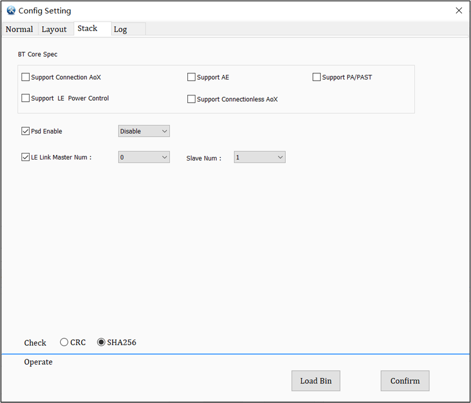
PSD Enable
PSD function switch, PSD is used to scan the congestion status of each channel in the air. When PSD is enabled, the channels used by Bluetooth will refer to the scanning results of PSD.
LE Master Link Num
The maximum number of LE connections for a master role.
LE Slave Link Num
The maximum number of LE connections for a slave role.
Support LE AE ADV
Whether to support LE Extended Advertising. If LE AE ADV is not supported, the LE AE ADV Task Number field cannot be set.
LE AE ADV Task Number
The number of tasks supported by LE Extended Advertising.
Support LE AE SCAN/INIT
Whether to support LE Extended Advertising Scan and Initiating. If LE AE SCAN/INIT is not supported, the LE AE SCAN Task Number, LE AE ADV Report Unit Number, and LE AE duplicated adv filter list size fields cannot be set.
LE AE SCAN Task Number
The number of tasks supported by LE Extended Advertising Scan.
LE AE ADV Report Unit Number
The maximum number of ADV reports that can be temporarily stored by the Bluetooth Controller in LE Extended Advertising Scan mode at the same time.
LE AE duplicated adv filter list size
The maximum number of duplicated ADV data that can be stored by the Bluetooth Controller at the same time, which is used to filter duplicate ADVs received from the air.
LE AE Adv Data Packet Number
The maximum number of extended ADV data that can be temporarily stored by the Bluetooth Controller at the same time, which is used to store the extended ADV data to be transmitted.
Support LE PA
Whether to support LE Periodic Advertising. If it is not supported, the LE PA Number field cannot be set.
LE PA Number
Several groups of Periodic Advertising that can be supported.
Support LE Isochronous
Whether to support CIS/CIG/BIS/BIG. If CIS/CIG/BIS/BIG is not supported, the LE CIG/CIS/BIG/BIS Number field cannot be set.
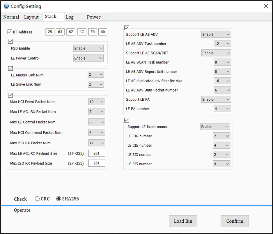
Set the device address of Bluetooth, used to identify each Bluetooth device.
PSD Enable
PSD function switch, PSD is used to scan the congestion status of each channel in the air. When PSD is enabled, the channels used by Bluetooth will refer to the scanning results of PSD.
LE Power Control
Used to determine whether to enable the LE Power Control feature on the IC.
LE Master Link Num
The maximum number of LE connections for a master role.
LE Slave Link Num
The maximum number of LE connections for a slave role.
Max HCI Event Packet Num
The maximum number of HCI Events that can be temporarily stored by the Bluetooth Controller at the same time.
Max LE ACL RX Packet Num
The maximum number of LE ACL Rx Data (controller to host) that can be temporarily stored by the Bluetooth Controller at the same time.
Max LE Control Packet Num
The maximum number of LE Control Packets that can be temporarily stored by the Bluetooth Controller at the same time.
Max HCI Command Packet Num
The maximum number of HCI Commands that can be temporarily stored by the Bluetooth Controller at the same time
Max ISO RX Packet Num
The maximum number of LE ISO Rx Data (controller to host) that can be temporarily stored by the Bluetooth Controller at the same time.
Max LE ACL RX Payload Size
The maximum payload size for each LE ACL Rx Data.
Max ISO RX Payload Size
The maximum payload size for each LE ISO Rx Data.
Support LE AE ADV
Whether to support LE Extended Advertising. If LE AE ADV is not supported, the LE AE ADV Task Number field cannot be set.
LE AE ADV Task Number
The number of tasks supported by LE Extended Advertising.
Support LE AE SCAN/INIT
Whether to support LE Extended Advertising Scan and Initiating. If LE AE SCAN/INIT is not supported, the LE AE SCAN Task Number, LE AE ADV Report Unit Number, and LE AE duplicated adv filter list size fields cannot be set.
LE AE SCAN Task Number
The number of tasks supported by LE Extended Advertising Scan.
LE AE ADV Report Unit Number
The maximum number of ADV reports that can be temporarily stored by the Bluetooth Controller in LE Extended Advertising Scan mode at the same time.
LE AE duplicated adv filter list size
The maximum number of duplicated ADV data that can be stored by the Bluetooth Controller at the same time, which is used to filter duplicate ADVs received from the air.
LE AE Adv Data Packet Number
The maximum number of extended ADV data that can be temporarily stored by the Bluetooth Controller at the same time, which is used to store the extended ADV data to be transmitted.
Support LE PA
Whether to support LE Periodic Advertising. If it is not supported, the LE PA Number field cannot be set.
LE PA Number
Several groups of Periodic Advertising that can be supported.
Support LE Isochronous
Whether to support CIS/CIG/BIS/BIG. If CIS/CIG/BIS/BIG is not supported, the LE CIG/CIS/BIG/BIS Number field cannot be set.
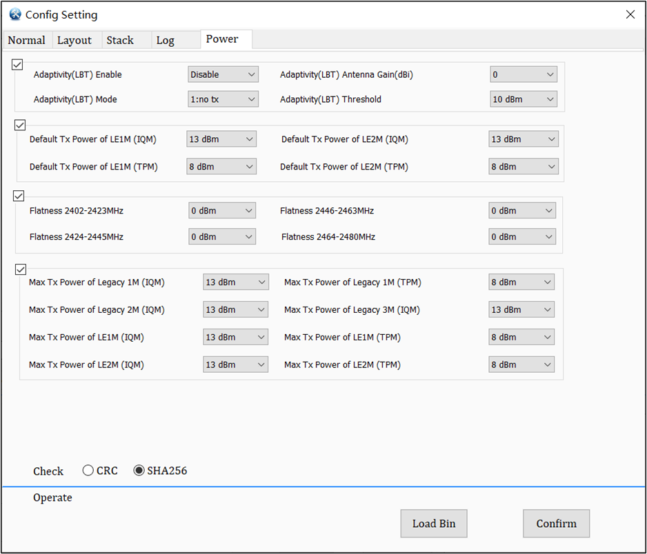
LBT is used for interference avoidance. This setting enables the Adaptivity feature, and only when this feature is enabled, the subsequent LBT settings will take effect.
Adaptivity (LBT) Mode
There are two modes when LBT is enabled.
no tx: no more tx.
reduce tx: reduce power to do tx.
Adaptivity (LBT) Antenna Gain
Actual antenna gain of product, with a step size of 0.5 db.
Adaptivity (LBT) Threshold
Used to set the threshold for LBT enablement. LBT will be triggered only when target power + gain > threshold.
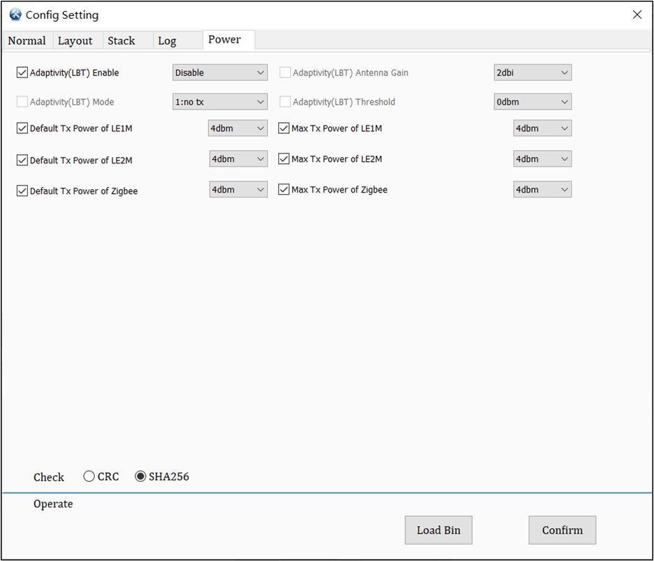
Support 4 dbm
After checking, the tx power can choose 4 dbm, unchecked maximum is 0 dbm. This item will decide whether to display or not according to the IC. If it is tx1, this item will be shown. Otherwise, this item will not be shown.
Tx Power related items
Power can select according to the test requirements.
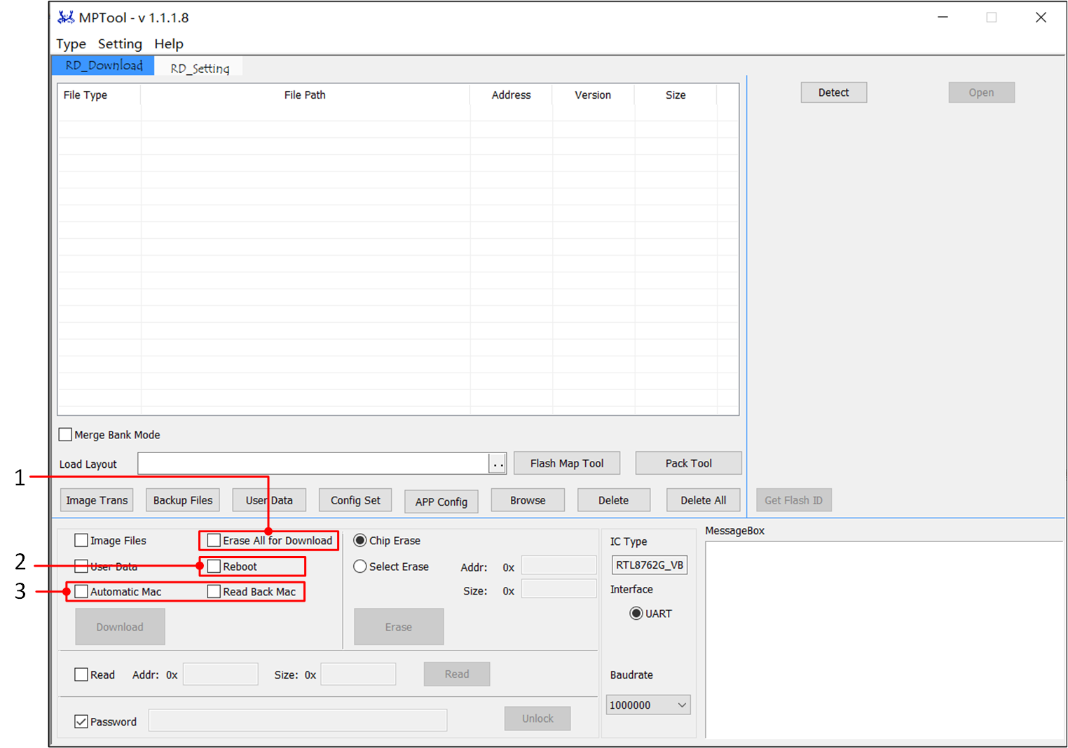
The separate image file can be directly downloaded into the chip in Debug Mode or can be included in a package file for production programming. Different ICs require different files; common files are listed below.
When the Erase All for Download option is selected during the downloading process, the entire flash memory will be erased before starting the writing process. If this checkbox is not selected, only the necessary files will be erased before the downloading process.
Reboot
When the Reboot checkbox is selected during the download process, the IC will automatically reboot after the download is completed.
Automatic Mac & Read Back Mac
In Debug Mode, the Bluetooth address can only be set using the BT Address option in the [Config Setting] page, as shown in the figure below. At the same time, it supports automatic addition one by one of Bluetooth address and read back Mac.
Click Config Set button to access [Config Setting] page. Set up Config parameters and Confirm the settings. The generated ConfigFile will be loaded at the corresponding location. For more details, please refer to the Config Files .
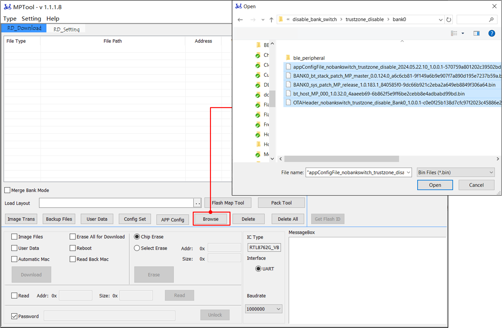
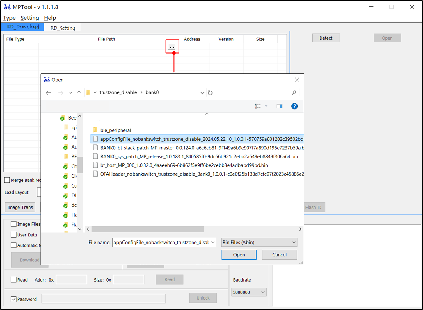
Select image files to be downloaded, click Browse button to batch import Image files as shown in the figure below.
Batch import image file, or select image file in the File Path item of list box to add single image file.
Click the User Data button to edit user-defined data other than the layout, be careful not to conflict with the flash layout.
The way to add the User Data file is analogous to adding an image in the above step. For more details, please refer to the User Data Download .
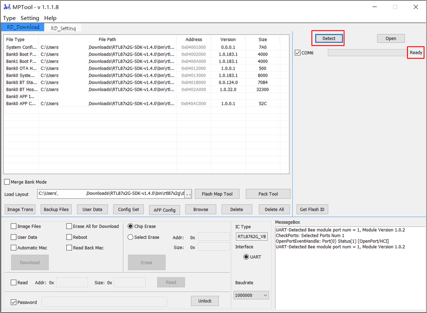
Click Detect to detect port numbers, the port displays Ready status after detection, as shown in the figure below.
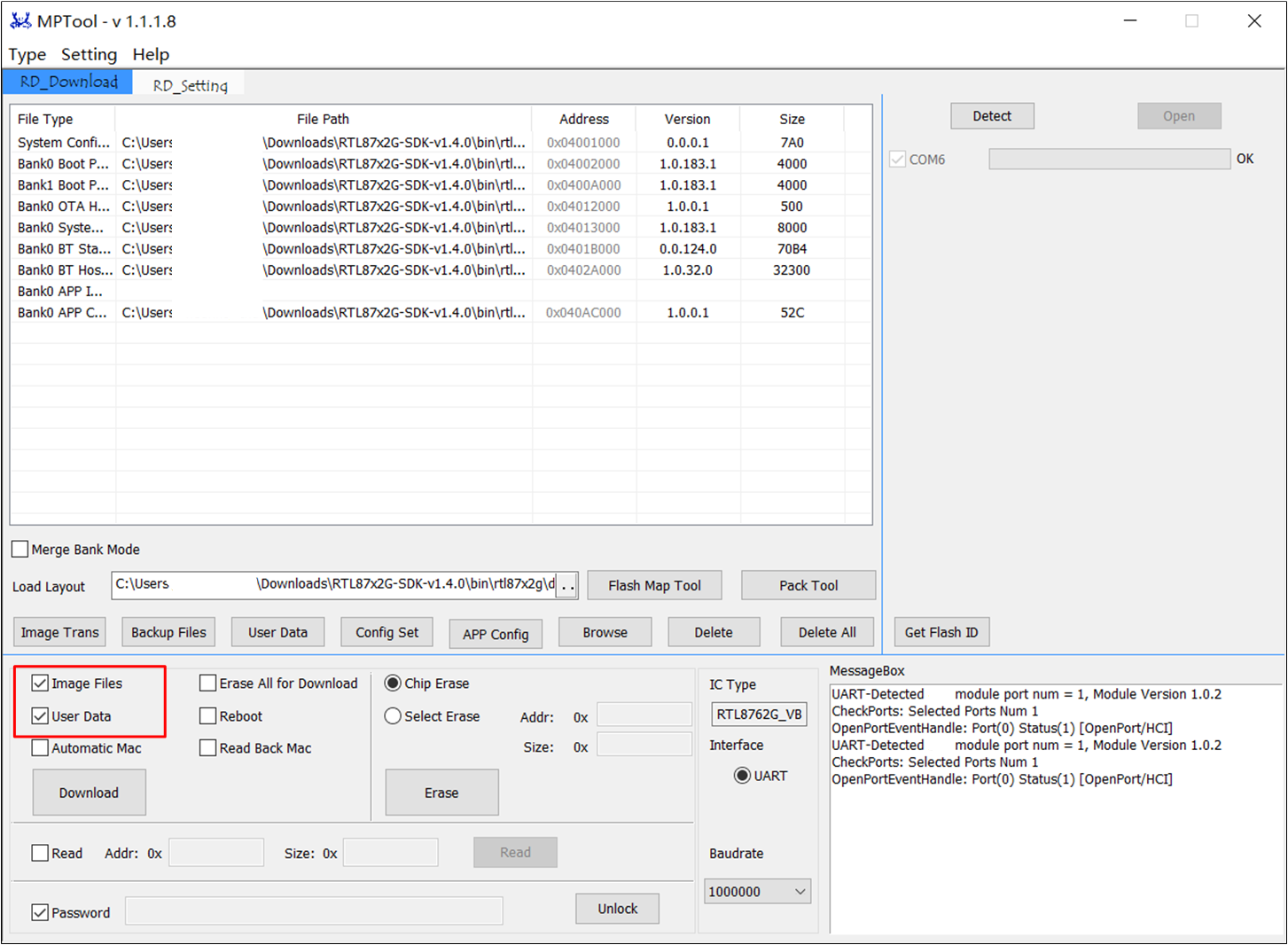
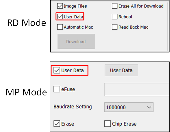
Select and check the Image Files and User Data checkboxes to choose whether to download the corresponding files.
Image File: After selecting Image Files, the configured image file will be downloaded. This option is selected by default.
User Data: After selecting User Data, the configured User Data file will be downloaded. Once User Data is configured, clicking Confirm will select this checkbox by default, and clicking Cancel will deselect it by default.
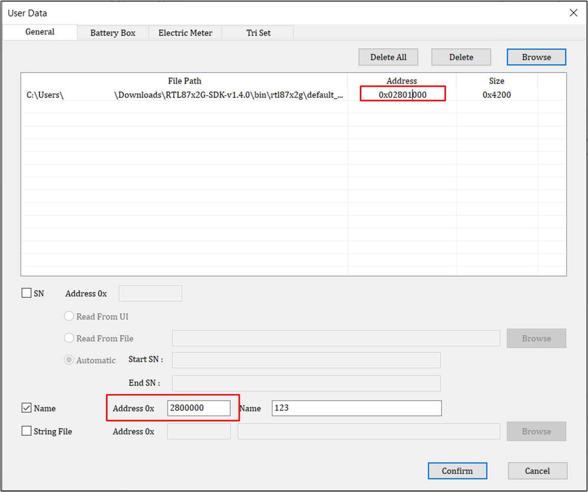
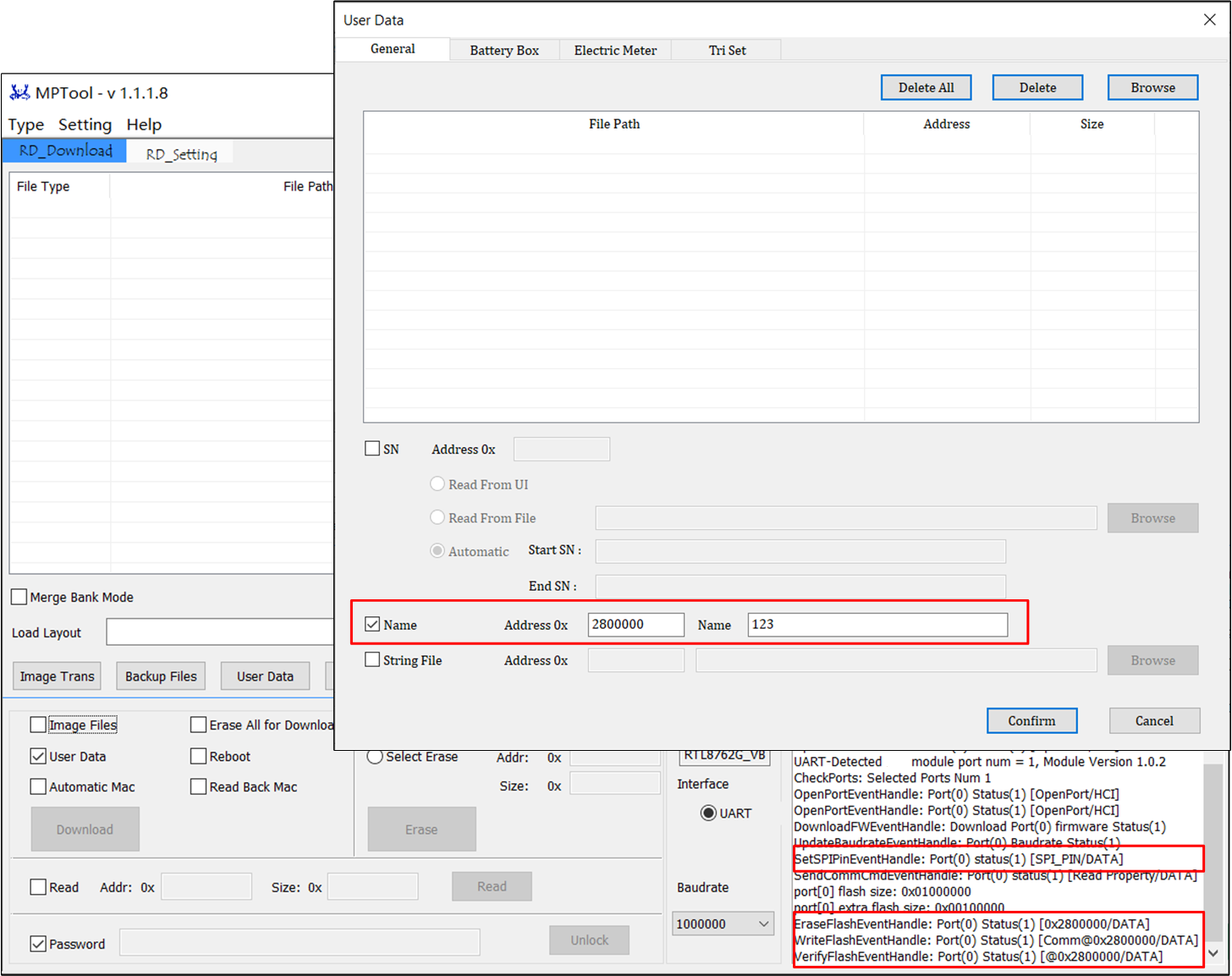
Click the User Data button to open the [User Data] page for configuration.
The download address of external flash data starts from 0x2800000.
After configuring the custom data, click Confirm, at which point the checkbox for User Data on the RD side will be automatically checked; then proceed with the normal download.
Note
Address conflicts won't be checked, so users need to ensure the correctness of the download address.
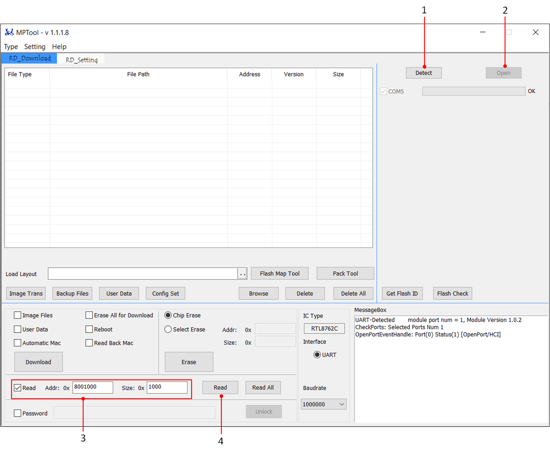
In Debug Mode, MP Tool supports reading the Flash and saving it as a ReadBack.bin file.
To read back Flash using UART, it is necessary to confirm that the chip is in MP Mode.
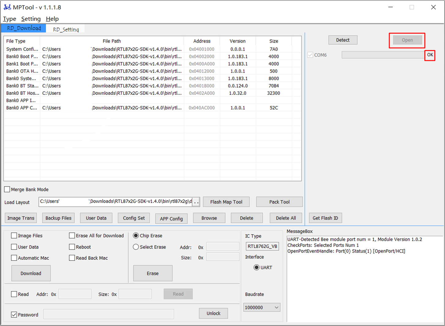
Click Detect to detect the port.
Click Open to open the port.
Check Read, enter the starting address and size of the flash to be read back in the interface. The read address must be aligned to 4KB, and the maximum length for a single read cannot exceed 16 Mbytes;
Finally, click the Read button to complete the readback. The readback ReadBack.bin file is saved in the tool folder.
Additionally, the [Read All] feature supports reading back all the flashed files from the Flash. Each file is named based on its file type, download address, and size, and is saved in the ReadAll folder. It is shown in the figure below.
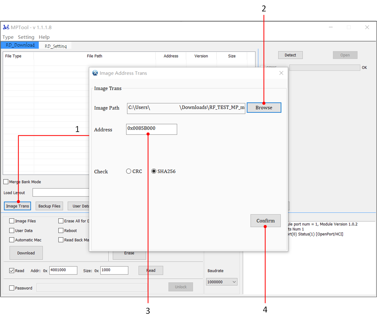
When the download address in the original image (only RF Test Patch) does not match the patch address planned in the actual flash map, the [Image Trans] feature can be used to convert the original image to a new image that matches the patch address according to the flash map.
Click Image Trans button to enter the Image conversion page;
Import the image to be converted;
Fill in the converted address, and select the verification type;
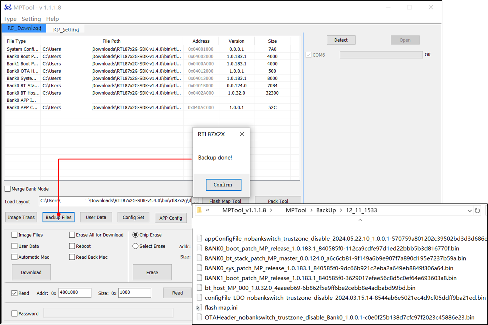
The [Backup] feature allows users to backup all the files currently configured in the Debug Mode interface to the Backup folder.
By clicking the Backup Files button, a Backup folder will be created in the same directory as MP Tool, and a folder with the current time will be created within the Backup folder as the backup directory.
The files listed in the RD page file list and the loaded flashmap.ini will be copied to the backup directory.
When the UserData checkbox is selected, a User Data folder will be created in the backup directory, and the configured User Data files will be copied to the User Data folder.
The [Flash Check] feature allows you to read back data from the Flash to determine if the Flash can boot normally.
Click Detect to detect the port;
Click Open to open the port;
Clicking the Flash Check button, the tool will read the data from the Flash and analyze it. Once the analysis is complete, the results will be displayed in a pop-up dialog box.
When using this feature, the results will be saved in the Flash Check folder, which includes a bin file of the read-back flash data and a txt file with the analysis results.
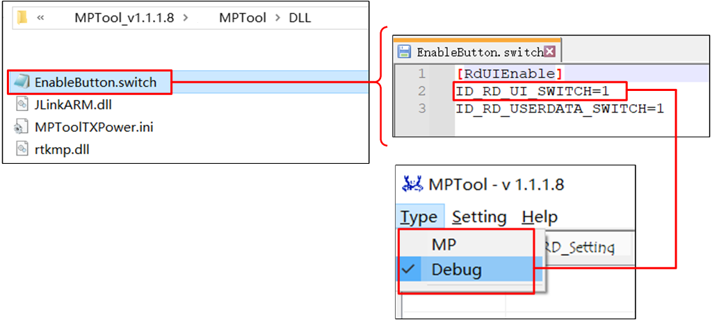
There is a file EnableButton.switch in the DLL folder. By setting the value of the ID_RD_UI_SWITCH field under [RdUIEnable], users can disable Debug Mode.
Default ID_RD_UI_SWITCH=1, Debug Mode is always on.
If it is given to the factory and users want to turn off Debug Mode, just write the value ID_RD_UI_SWITCH=0.
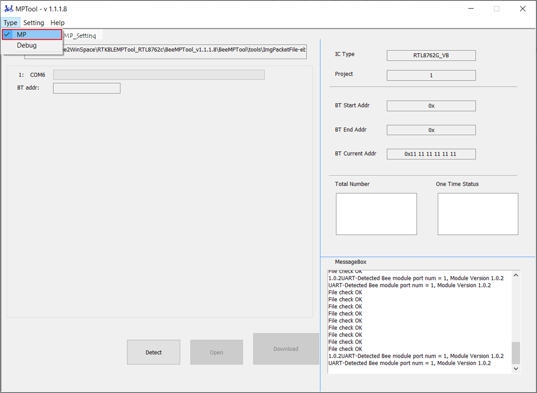
Users can switch between Debug Mode and MP Mode by the Type item of menu, as shown in the figure below.
Developers can set the interface parameters before mass production and then lock the interface by clicking on the LOCK button.
When parameters need to be modified, the user must first unlock the interface by entering a password through the UNLOCK function.
In the mass production stage, the packet file to be downloaded needs to be prepared, which is generated by the MP Pack Tool.
In the debugging stage, various image files such as Patch,:file:APP,:file:APP data,:file:Config File,:file:OTA header file etc. need to be prepared.
If the loaded packet file contains an MD5 checksum, the file will be checked using MD5 checksum; otherwise, no relevant checks will be performed. In the debugging process, MD5 checksums will be performed on each individual file.
The tool supports custom data programming in both MP Mode and Debug Mode. The relevant settings need to be made on the User Data page.
The data on the User Data page is data that needs to be programmed other than the flash map, and users need to ensure that there is no address conflict.
Data files programmed using User Data cannot be upgraded via OTA and are suitable for programming large app data that does not require updates.
During production, if there is a need to package user data, the MP Pack Tool can be used to package with User Data. Please refer to MP Pack Tool .
After configuring the User Data and clicking Confirm, the tool will automatically check the User Data checkbox.
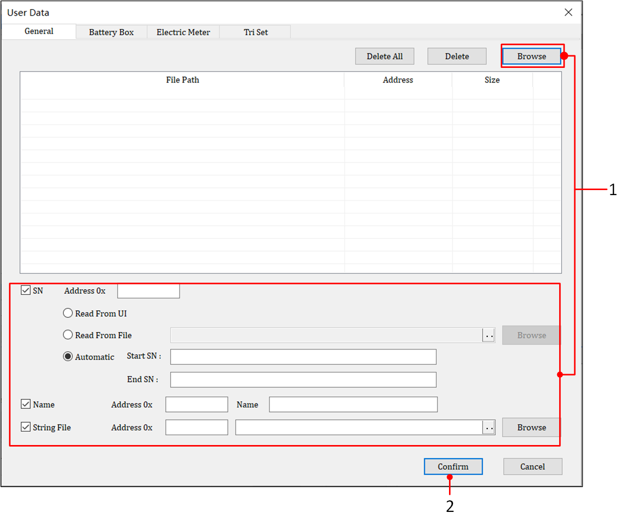
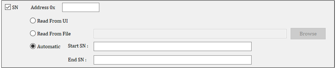
On the User Data page, support for SN number updates in three settings:
Read From UI: Obtain from the interface (only supports production mode)
Read From File: Obtain from a file
Automatic: Custom settings
To use it, check the SN checkbox, configure the SN programming location in the Address field, and select the method of obtaining the SN. The tool will write 16 bytes of data in hexadecimal format.
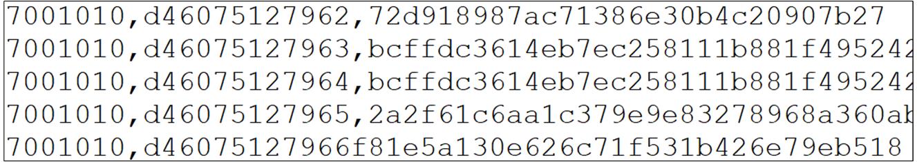
If an SN is set during production, the corresponding SN to be written will be displayed in the production interface. The SN file style is as shown in the figures below.
On the User Data page, users can configure the device name. Check the Name checkbox, configure the Name programming location in the Address field, and enter the device name in the Name field. The device name should be a string of ASCII characters.
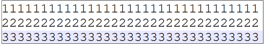
The User Data page supports settings for string files. Check the String File checkbox, configure the String File programming location in the Address field, and load the desired string file in the file loading area.
The tool will write the strings from the file into flash memory in ASCII format. It supports a maximum of 100 bytes of data. Every device can be a different string line. The string file style is as shown in the figure below.
When programming an image by MP Tool, users may encounter exceptions of open port failed or image download failed. The following are some common handling methods for the exception.
Exception
Solution
Incorrect hardware connection
Check hardware connection, detect and open the port again after making sure the connection is correct.
Invalid device port
Check all ports of the PC, remove the useless and interferential COM port, then detect and open the port again.
Chip in normal mode
Pull down P0_3 and reset MCU, then system mode will switch to MP Mode. Users can detect and open the port again.
Inconsistent chip type
Check whether the chips are consistent or not.
Other errors
Pull down P0_3 and reset MCU, then detect and open port again.
Exception
Solution
UART communication is not stable
Use stable power source to supply power to UART, select FT232 chip with good performance.
Other errors
Pull down P0_3 and reset MCU, then detect and open port again.
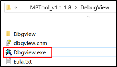
If the error always exists, there is a tool of Dbgview in the DebugView decoder, users can open this tool first, then reappear the error, the Dbgview tool will produce log, just send the log to Realtek.