This article introduces the security mechanisms and their usage in the RTL87x2G chip. The security mechanisms include:
Secure boot: verifies the authenticity and integrity of the bootloader and firmware to prevent unauthorized or malicious code execution.
Image encryption: encrypts firmware to ensure its confidentiality and integrity, preventing unauthorized access and tampering.
Factory data encryption: encrypts sensitive data in device memory, such as encryption keys or user-specific information, reducing the risk of data breaches.
eFuse programming: stores critical information like passwords or encryption keys in hardware-based eFuse memory, protecting it from extraction or tampering.
Debug port control: restricts access to the SWD interface, allowing authorized personnel to use it for debugging purposes through a password-only mechanism.
In summary, the security mechanisms in RTL87x2G provide a comprehensive and reliable approach to protect the integrity, confidentiality, and reliability of the device and its data.
For secure devices, it is critical to enforce firmware authenticity to protect against the execution of malicious software. Secure Boot is embedded in the ROM of the RTL87x2G series and disabled by default. To enable it, the related eFuse should be programmed by MP Tool.
Secure Boot is used to ensure the integrity and authenticity of images, SHA256 is used for integrity and ECDSA is used for authenticity. If any image authentication fails, the IC will reset without jumping into the unauthenticated image.
The Image Encryption solution is developed based on Flash Security. The APP image can be encrypted or not according to your needs.
Flash Security (Flash-Sec for short), also known as Flash on-the-fly, is a technology that allows the CPU to directly access encrypted flash data. The principle is that when the CPU accesses Flash-Sec encrypted data, it first decrypts the data with the help of the Flash-Sec hardware module and then accesses the decrypted data.
Flash-Sec utilizes the AES encryption algorithm with CTR mode, and the encryption key length is 128 bits. Flash-Sec supports configuring up to 8 regions for users. Currently, Patch Image uses Region #0 by default, and App Image uses Region #1 by default.
Note
Please note that the base address of each region must be 4KB aligned.
During the IC startup process, the encrypted image will be initialized by Flash-Sec (region configuration, key setting, etc.). If the key is not burned or the burned key does not match the encryption key, Flash-Sec decryption will fail.
During the process of manufacturing equipment, it is possible to generate some information related to production, which is referred to as factory data. Some of this factory data may contain sensitive information, such as key pairs used for device authentication, specifically private and public keys. The protection of private keys and similar information is crucial. Therefore, RTL87x2G provides a mechanism to protect factory data by encrypting it and storing it in flash memory.
Additionally, encryption and decryption keys are generated based on differentiated information on the device. During device startup, the keys are securely loaded into the AES engine within a secure execution environment, allowing applications to decrypt factory data stored in the flash memory without directly accessing the keys.
It is crucial to implement a special mechanism to safeguard the image encryption key from potential leakage since both the encryption and decryption processes employ the same 128-bit key. To address this, a new key' is generated when passing the encryption key to the Encryption Tool. This newly generated key' is also published and downloaded into the Flash Config of the IC.
During the download process, the Download Tool decrypts the new key' to retrieve the original key and simultaneously reads the UUID of the IC. These pieces of information are combined to generate a new key'', ensuring that each IC possesses a unique key (key''). This approach helps enhance the security of the encryption process and mitigates the risk of key compromise.
The SWD interface is a crucial debug port that plays a vital role in program debugging. However, it also introduces the risk of exposing data and code. To mitigate this risk, the security mechanism offers three methods to control the SWD interface: Open, Close, and Password Control. In the case of Password Control, the SWD interface remains closed unless the correct password is received through the UCI UART. This ensures that unauthorized access to the SWD interface is prevented unless the valid password is provided.
Similar to the encryption key, the password is programmed in the eFuse of the IC. When the password is received through the HCI UART, the IC will automatically reboot to verify if the password is correct. The function configured as Password Control remains closed unless the correct password is provided. Every time the IC reboots, the password needs to be retyped to activate the function.
RTL87x2G provides 3 security levels: 0, 1 and 2. A larger number indicates a higher security level, which will affect debug and re-program of eFuse. Function control of each module under a different security level is listed in the below table. It is suggested to configure the security level to level 1 during minor trial production and level 2 in mass production.
Secure boot is a mechanism that ensures the authenticity of firmware during the device startup process to protect the device from malware attacks. The specific method involves signing the firmware with ECDSA and using secure boot code located in ROM and keys pre-burned into eFuse to verify the signature during device startup. The device can only start normally if all firmware passes the verification. (If the device does not require secure boot, this section can be skipped without affecting other security mechanisms.)
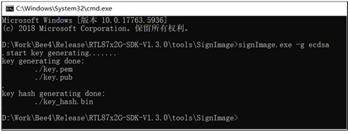
Realtek provides a signing tool called signImage (located in RTL87x2GSDK\tools\SignImage), which integrates key generation and firmware signing functions. Users can get specific usage instructions by running signImage.exe--help .
To generate keys, use the following method:
Run signImage.exe-gecdsa (where the parameter -g stands for generating keys, and ecdsa represents the type of key). This will generate the following three files:
key.pem (private key)
key.pub (public key)
key_hash.bin (Hash value of the public key, used to verify the public key)
Different firmware allows the use of different key pairs (up to 3 sets). Therefore, you can refer to the following script to generate 3 sets of key pairs: ken_gen.bat
In this section, you will learn how to enable secure boot, configure signature keys, and burn them into the IC's eFuse. The chip does not have secure boot enabled at the factory, so it can run unsigned firmware.
Warning
Once secure boot is enabled, the chip will only run correctly signed firmware.
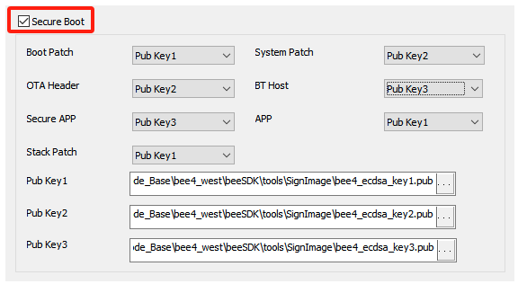
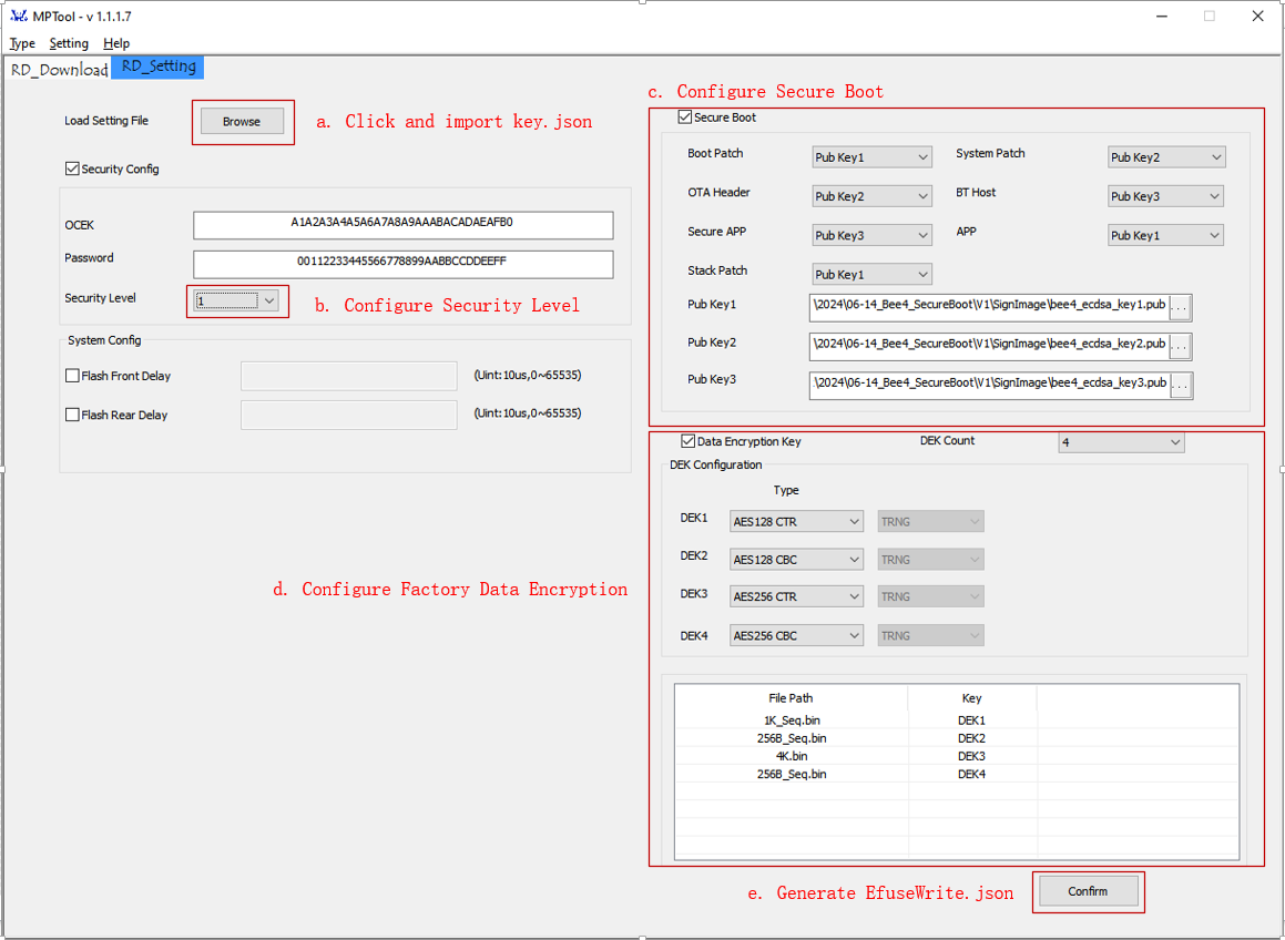
In MP Tool RD Setting mode, enable secure boot (check the SecureBoot box) and select the corresponding public key for different firmware, as shown in the figure below.
Please note the following points:
Different firmware can use the same key.
Firmware must be signed with the corresponding private key.
eFuse bits can only be burned from 1 to 0, not from 0 to 1. Once the public key is burned, it cannot be modified.
For projects without TrustZone enabled (i.e., without the Secure APP firmware), a public key still needs to be selected for the Secure APP.
Boot Patch, OTA Header, Secure APP (if TrustZone is not enabled, this file is excluded), Stack Patch, System Patch, BT Host, and APP all need to be signed. The signing process still uses the signing tool mentioned in Generating Signature Keys (signImage). Below are example commands and parameter descriptions:
-recdsa_key1.pem : Specify the private key file (please replace with the actual private key file)
-csha256 : Perform SHA256 checksum on the firmware
-p***.bin: Specify the firmware file to be signed (please replace with the actual firmware file)
The method for programming signed firmware is the same as for unsigned firmware.
Note
Once secure boot is enabled, every file in the OTA Bank of the Flash layout with a size greater than 0 must be burned, even if some data files do not require signing. Otherwise, the chip will not boot properly. For example, in the Flash layout (refer to the project's flash_map.h file), if the APPConfigFile is set to 4KB, this file must be burned.
Edit tools\keys\key.json file to configure OCEK and PASSWORD, where OCEK and PASSWORD are plaintext that need protection. When asking Realtek to do IC defect analysis, you need to provide the plaintext password here.
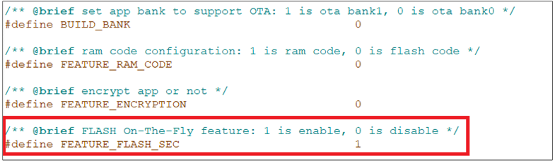
To generate a Flash-Sec encrypted APP image, the following modifications need to be made.
Change MACRO FEATURE_FLASH_SEC in App's mem_config.h to 1, as shown in Enable APP encryption by Flash-Sec. The default value is 0, which means no encryption.
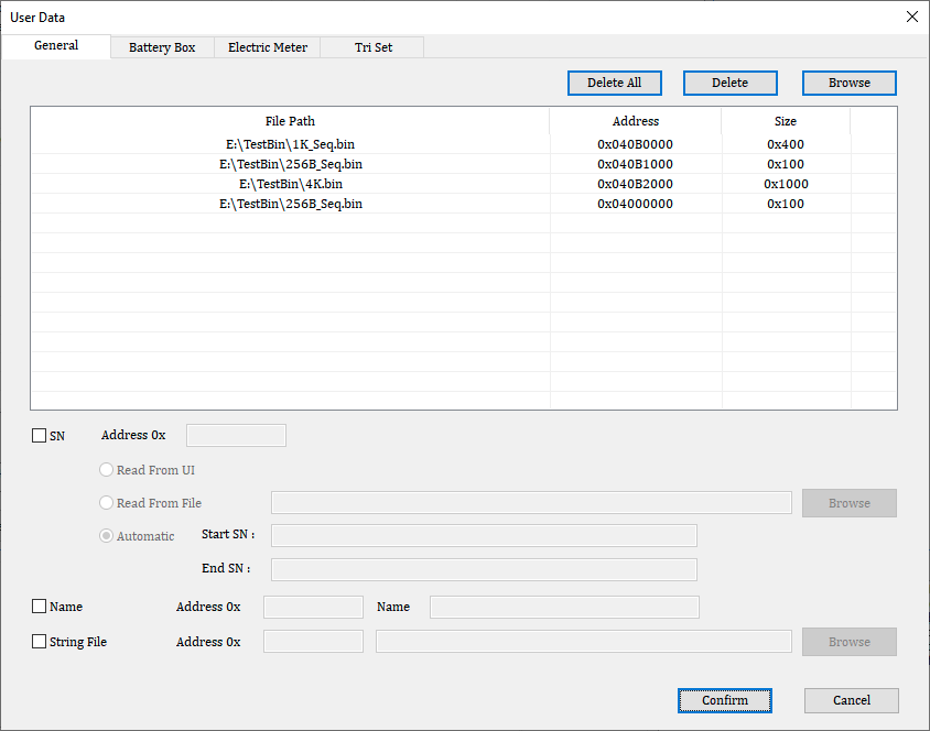
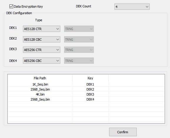
MP Tool has supported encrypted Factory Data since version 1.1.1.7. Factory Data encryption uses the AES128 or 256 algorithm and supports CBC and CTR modes. The key for encrypting Factory Data is called DEK (Data Encryption Key), and up to four keys are supported. Factory Data is stored as User Data, and the User Data file itself does not contain address information, so the address needs to be manually configured in MP Tool.
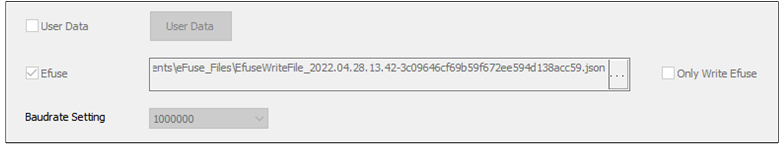
When downloading multiple Factory Data files, MP Tool needs to know the programming address of each Factory Data and which DEK was used. This information can be configured through MP Tool RD mode and is ultimately recorded in the EfuseWrite.json file. This file, originally used to describe the eFuse information to be burned, is also used here to describe DEK information and User Data information (including DEK selection, User Data address, and file length). Currently, only production mode supports programming this file, so encrypted Factory Data needs to be included in the package and burned together with EfuseWrite.json in production mode. (If the device does not require encrypted Factory Data, this section can be skipped without affecting other security mechanisms.)
First, configure the Factory Data to be encrypted in the User Data dialog.
The number of Factory Data files that can be encrypted is currently limited by Flash capacity, with no software limitations.
DEK is stored at the 3072-byte position of the first sector of Flash, at address 0x4000C00. If Factory Data is placed in the first sector, it cannot exceed 3072 bytes.
The maximum supported Factory Data size is 16K bytes.
Please include the header file aes_api.h in the APP, and then use the following APIs to perform encryption and decryption operations. CBC mode requires the Factory Data length to be a multiple of 16, while CTR mode has no such restriction.
The 2.5V ± 10% restriction has been lifted when programming eFuses on the RTL87x2G. As long as the chip is supplied with normal power, the eFuse can be programmed.
When the security level is set to 1 or 2, the SWD interface is disabled as a security measure.
However, developers have the ability to reactivate the SWD interface using the Password debug feature. This allows authorized developers to regain access to the SWD interface for debugging purposes while maintaining the overall security of the system.