RFTestTool
Test Environment
Before using the RFTestTool, the device must download the test images first and run in the [MP Mode]. Users can use MP Tool to configure the 'MP Mode'.
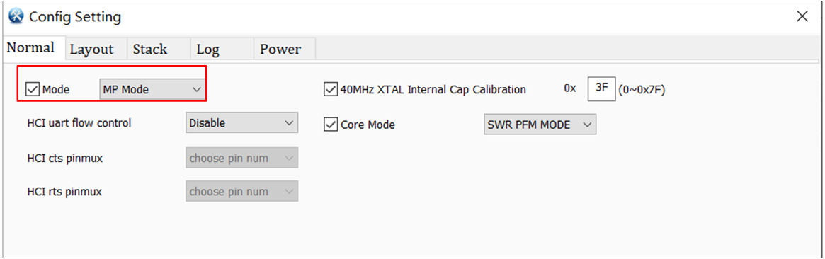
Configure MP Mode
Main Function
The RFTestTool includes the following two test modes. The main page function blocks are as follows.
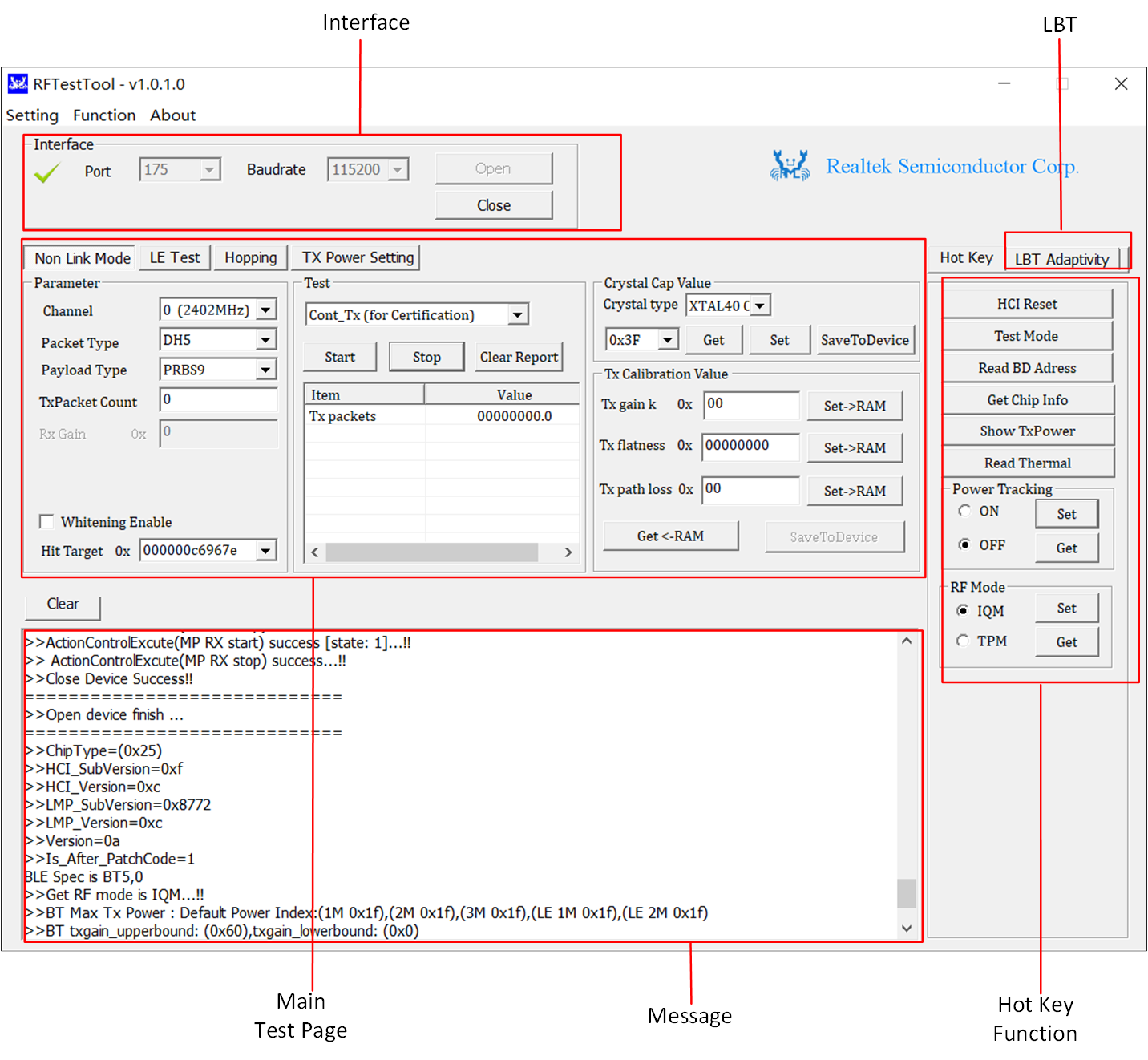
RFTestTool Main Page
Check the serial port number in Device Manager, the Baud rate is 115200.
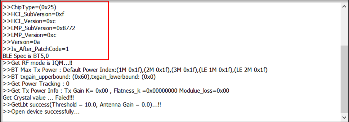
When users click the Open button, the status in the upper left corner changes to
 , indicating that the device has been successfully opened and the firmware patch has been downloaded.
Users also can confirm this by checking the 'Message' box, when >>Device Open successfully... appears, it means the device has been successfully opened.
The main test pages are as follows.
Page |
Test Function |
|---|---|
Include BR/EDR, Single Tone, Continue tx...test. |
|
BLE packet TX/RX test. |
|
Hopping test for certification. |
|
Set Tx power. |
|
Zigbee packet TX/RX test. |
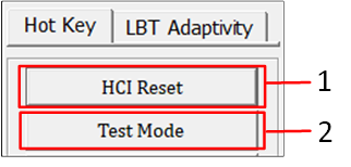
These hotkeys will be different depending on the chip. But the 'HCI Reset' is generally supported.
Item |
Description |
|---|---|
HCI Reset |
Device execute 'HCI Reset' function. |
Test Mode |
Enter to test mode for BR/EDR signaling mode test, depends on chip. |
Read BD Address |
Read BD Address from device. |
Get Chip Info |
Get information from device, ex: LMP Version. |
Show TxPower |
Read current Tx power. |
Read Thermal |
Read thermal raw data from device. |
Power Tracking(Set and Get) |
Disable or enable thermal power tracking, depends on chip. |
RF Mode |
Set/Get IQM or TPM mode, depends on chip. |
This is for the CE/SRRC certification testing. Users can set LBT related parameters to detect the device's interference avoidance function. The CE specification only needs to be supported when EIRP > 10dBm. If LBT is turned on, the device will stop sending packets after interference is detected (please select this mode during certification).
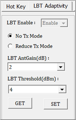
LBT Function
Parameter |
Description |
|---|---|
LBT Enable |
Enable LBT function or not. |
No Tx Mode |
If LBT is enabled, the device will stop TX. |
Reduce Tx Mode |
If LBT is enabled, the device will reduce Tx power during transmission, and it's just an option for users. |
LBT AntGain |
Gain value of the antenna. |
LBT Threshold |
Used to set the threshold for LBT enablement. LBT will be triggered only when target power + gain > threshold. |
Signaling (Link) Test Mode
The device only needs to enter the signaling test mode and establish a connection with an instrument that supports signaling testing (such as 8852B), to directly perform Bluetooth RF performance test. This test mode complies with the Bluetooth standard test.
BR/EDR Signaling (Link) Test
Enter Signaling (Link) test mode, please follow the operations below.
Click HCI Reset button to reset.
Click Test Mode button to enter DUT Test Mode (Signaling test mode).
After test, click HCI Reset button to exit DUT Test Mode.
BR/EDR Signaling (Link) Test
The BR/EDR Signaling (Link) test hardware environment shows as:
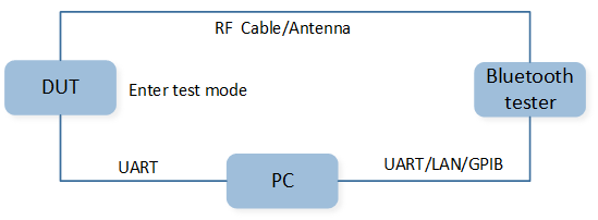
BR/EDR Signaling (Link) Test Hardware Environment
BLE Signaling (Link) Test
DUT and instrument (such as 8852B) are connected via serial port for DTM testing, and two methods are supported:
HCI interface, just need to ensure the DUT is in [MP Mode].
2-wire UART interface, this mode needs to download the test app and be in [Normal Mode].
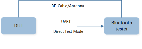
BLE Signaling (Link) Test Hardware Environment
Non-Signaling (Link) Test Mode
In Non-Signaling mode, Bluetooth does not need to be connected. The device can transmit and receive in this mode. Use a Non-Signaling instrument such as IQXel to test the Bluetooth RF performance. This chapter will explain how to use the RFTestTool to control the DUT for receiving and transmitting with the instrument.
Non Link Mode
The function of the Non Link Mode page is as below:
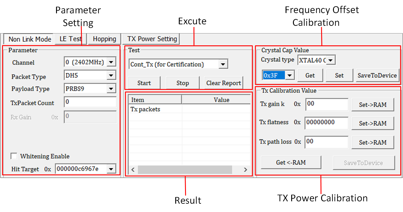
Non Link Mode Page
Parameter |
Value Range |
|---|---|
Channel |
BR/EDR: 0 ~ 78. BLE: 0 ~ 39. |
Packet Type |
BR/EDR: DH1, DH3, DH5, 2DH1, 2DH3, 2DH5, 3DH1, 3DH3, 3DH5, 1DM1, 1DM3, 1DM5, AUX1. BLE: LE1M, LE2M, LE coded S2, LE coded S8. |
Payload Type |
ALL0, ALL1, 0101, 1010, 0x0 ~ 0xF, 0000_1111, 1111_0000, PRBS9. |
Tx Packet Count |
0x0 ~ 0xFFFFFFFF. 0: 0xFFFFFFFF. |
Whitening Coeff Value |
0x00 ~ 0x7F: Enable Whitening. 0x80 ~ 0xFF: Disable Whitening. |
HitTarget |
Target BD_ADDR (6 bytes). |
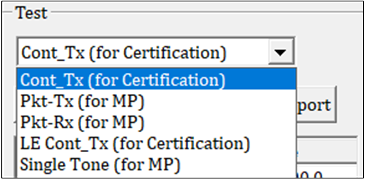
Functional testing, generally includes the following test items, and the test items supported depend on the chip.
Execute Block
Item |
Description |
|---|---|
Cont_Tx (for Certification) |
Transmit duty cycle 100% of Bluetooth standard, for BR/EDR. |
Pkt-Tx (for MP) |
Transmit RF signal packet of Bluetooth standard, for BR/EDR. |
Pkt-Rx (for MP) |
Receive RF signal packet of Bluetooth standard, for BR/EDR. |
LE Cont_Tx (for Certification) |
Transmit duty cycle 100% of BLE modulation RF signal, for BLE. |
Single Tone (for MP) |
Transmit continuous Single Carrier RF signal. |
This displays the result messages for both transmission and reception.
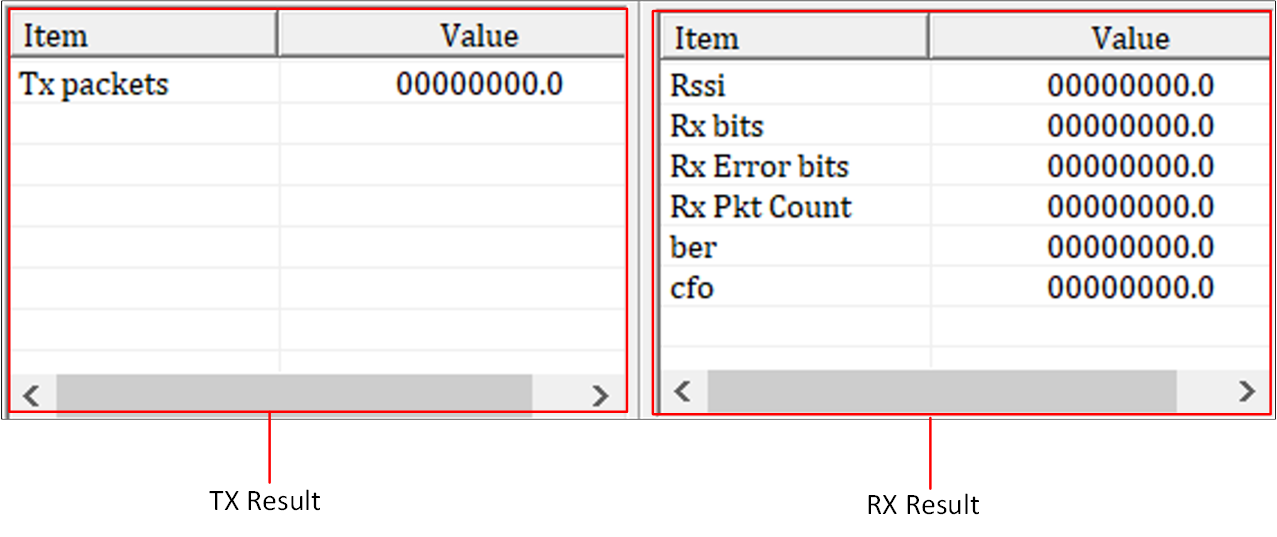
Result Block
Item |
Description |
|---|---|
Tx packets |
Transmit packets number. |
Rssi |
Received Signal Strength Indication. |
Rx bits |
Receive total bits number. |
Rx Error bits |
Receive error bits number. |
Rx Pkt Count |
Receive total packet number. |
ber |
Bit error rate. |
cfo |
Carrier frequency offset. |
-
Before writing the proper XTAL to flash, users should tune it. The following steps show how to adjust the crystal cap value for calibrating frequency offset.
Select new 'Crystal Cap Value'.
Click Set button.
Then use the instrument to measure the frequency offset.
Repeat the above steps until the measured frequency offset is within the measurement range.
Button |
Description |
|---|---|
SaveToDevice |
Save to flash. |
Get |
Get crystal cap value from register. |
Set |
Set crystal cap value to register. This is a temporary setting, if DUT reboots, the setting will be invalid. |
During adjustment the XTAL value, users can transmit a Single Tone signal. Finally, press SaveToDevice to write the correct XTAL value to flash.
Each parameter setting on the TX Power calibration page is expressed in hexadecimal format, if the value is negative, it is represented using 2's complement.
Users can use this page to manually adjust Tx power.
Parameter |
Description |
|---|---|
Tx gain k |
Adjusting Tx power usage, please use 2's complement to express. Generally, one step is 0.5 dB. For example, Tx gain k of 0x02 means an increase of 1 dB, and Tx gain k of 0xFC means a decrease of -2 dB. |
Tx flatness |
Adjust the Tx power of different frequencies, please use 2's complement representation. The usual step size is 0.25 dB. |
Tx path loss |
Set the loss from the IC RF pin to the RF connector. Generally the value is set to 0. The usual step size is 0.5 dB. |
Button |
Description |
|---|---|
SaveToDevice |
Save to flash. |
Set->RAM |
Set data to RAM (FW). This is a temporary setting. If the power is turned on again, the setting will be invalid. |
Get <-RAM |
Get data from RAM (FW). This is a temporary setting. If the power is turned on again, the setting will be invalid. |
The schematic diagram of the relationship between these parameters and tx power is as follows:
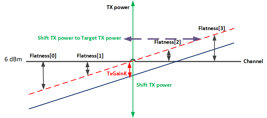
Schematic Diagram of the Relationship between these Parameters and Tx Power
Note
The current BLE SoC series chips do not need to calibrate TX Power, only need to calibrate frequency offset.
Bluetooth TX Test
This is the Bluetooth TX test for BR/EDR, the steps are as below.
Select 'Pkt-Tx (for MP)'.
Choose 'Channel'.
Choose 'Packet Type.' Ex: DH5.
Set 'Payload Type'. Ex: PRBS9.
Set 'Tx Packet Count'. 0: infinity.
Click Start button and start to test.
After testing, click Stop button.
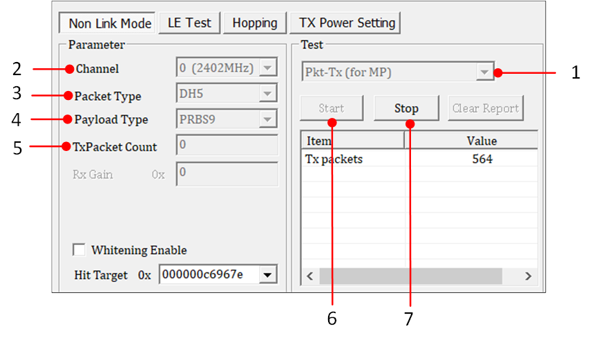
Bluetooth TX (Non-Signaling) Test
Bluetooth RX Test
This is the Bluetooth Rx test for BR/EDR, the steps are as below.
Select 'Pkt-Rx (for MP)'.
Choose 'Channel'.
Choose 'Packet Type'. Ex: DH5.
Set 'Payload Type'. Ex: PRBS9.
Set 'Hit Target'. Ex: 0x000000c6967e.
Click Start button and start to test.
After testing, click Stop button.
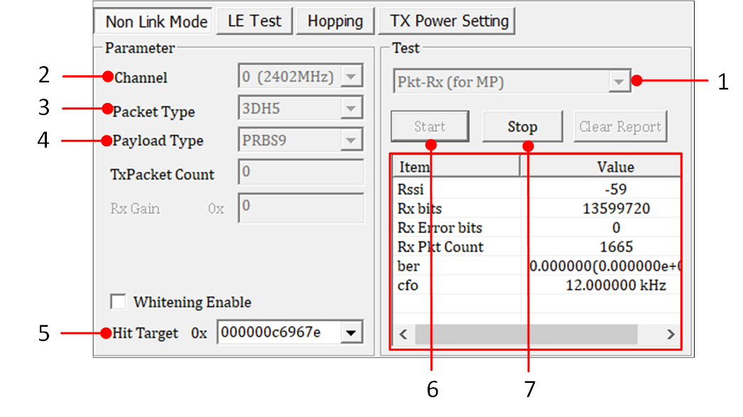
Bluetooth RX (Non-Signaling) Test
Note
The red rectangle of Bluetooth RX (Non-Signaling) Test shows received messages, RSSI, RX bits, RX error bits, RX packet counts, ber and cfo.
BLE Cont_Tx (duty cycle 100%) Test
The duty cycle for this test is 100%, which is used for certain laboratory certification tests.
Select 'LE Cont_Tx (for Certification)'.
Choose 'Channel'.
Choose 'Packet Type'. Ex: LE 1M PHY.
Set 'Payload Type'. Ex: PRBS9.
Set 'Tx Packet Count'. 0: infinity.
Click Start button and start the test.
After testing, click Stop button.
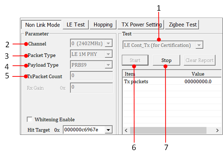
BLE Cont_Tx Test
Single Tone (CW) Test
This function transmits a single-carrier signal, and can be used for frequency offset calibration.
Select 'Single Tone (for MP)'.
Choose 'Channel'.
Click Start button and start the test.
After testing, click Stop button.
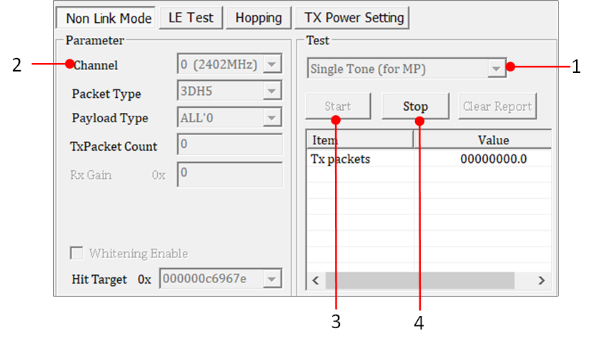
Single Tone Test
LE Test
This page uses the HCI command of the BLE standard. User can use this page to test the performance of BLE.
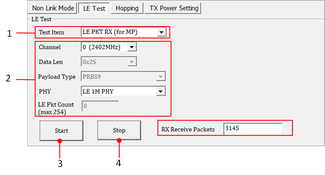
BLE TX/RX Test
Select 'LE PKT TX (for MP)' or 'LE PKT RX (for MP)'.
-
Select parameters.
BLE test parameters parameter
Value Range
Channel
0~39.
Data Len
0~255, Default: 37.
Payload type
PRBS9, 11110000, 10101010, PRBS15, All 1, All 0, 00001111, 01010101.
PHY
LE1M, LE2M, LRS8, LRS2.
LRS8 and LRS2 depend on chip.
LE Pkt Count(max 254)
0: infinity.
1~254.
Click Start button.
After testing, click Stop button.
Note
If user performs the 'LE Pkt RX' test, the received result will be displayed in the red rectangle of BLE TX/RX Test after clicking Stop. Then user can calculate the PER based on the number of received packets.
Hopping
Hopping test is used for some laboratory certifications such as FCC, CE, KC, BQB..., used to test 'Dwell time' and 'Band Edge'.
Name |
Value Range |
|---|---|
Packet Type |
DH1, DH3, DH5, 2DH1, 2DH3, 2DH5, 3DH1, 3DH3, 3DH5, LE. |
|
Start Channel & Stop Channel |
BR/EDR: 0~78. BLE: 0~39. It's best to have a difference of 20 channels between start channel and stop channel. |
Type |
Hopping: Hopping Mode. Fix Channel: Fix Channel Mode, BR/EDR supports this mode, BLE does not support. |
Ckb_Whitening |
Enable/Disable Whitening. |
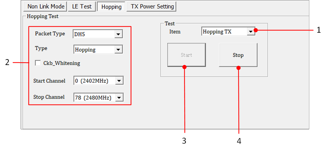
Hopping Test
TX Power Setting
This page is used to set the TX power, and it's a temporary setting. These settings depend on the chip. For example, if the chip does not support BR/EDR, Max Tx Power of legacy 1M/2M/3M will not be available.
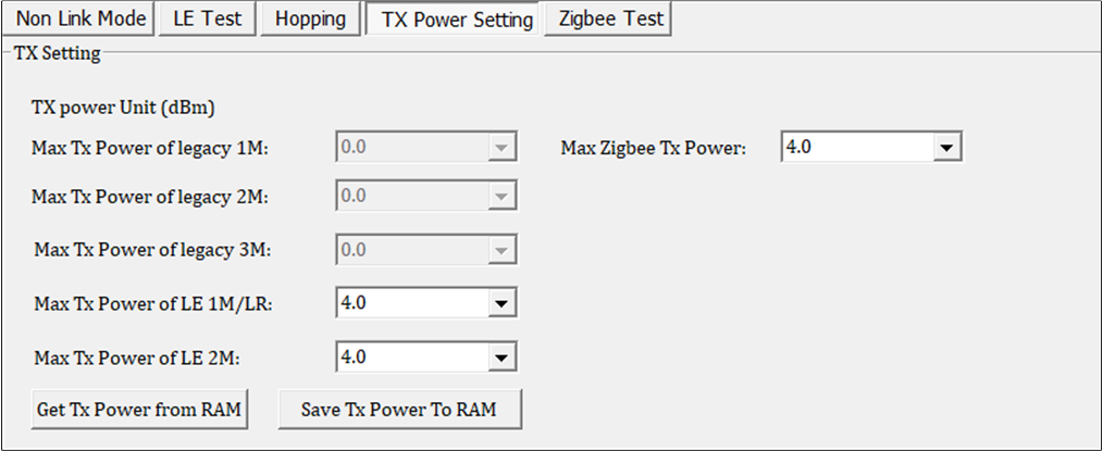
TX Power Setting
Name |
Description |
|---|---|
Max Tx Power of legacy 1M |
BR 1M Max Tx power. |
Max Tx Power of legacy 2M |
EDR 2M Max Tx power. |
Max Tx Power of legacy 3M |
EDR 3M Max Tx power. |
Max Tx Power of LE 1M/LR |
BLE 1M Max Tx power. |
Max Tx Power of LE 2M |
BLE 2M Max Tx power. |
Max Zigbee Tx Power |
Zigbee Max Tx power. |
Get Tx Power from RAM |
Get Tx power from RAM (FW) |
Save Tx Power To RAM |
Set Tx power to RAM (FW) |
Zigbee Test
The availability of this function's page depends on the chip. If the chip supports Zigbee, the tool will display this page.
Zigbee INIT
Before using Zigbee test, it's best to click the Zigbee MAC INIT button. If users click the HCI Reset button, then must click the Zigbee MAC INIT button again.
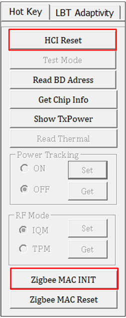
Zigbee INIT
Zigbee MP TX Test
Used to test the Error Vector Magnitude (EVM) and TX mask Emissions, the steps as below.
Choose 'MP TX'.
Choose 'Channel'.
Choose 'Tx Gain', unit (dBm).
Choose 'Payload Length'.
Set 'TxPacket Count'. 0: infinity.
Click Start button and start to test.
After testing, click Stop button.
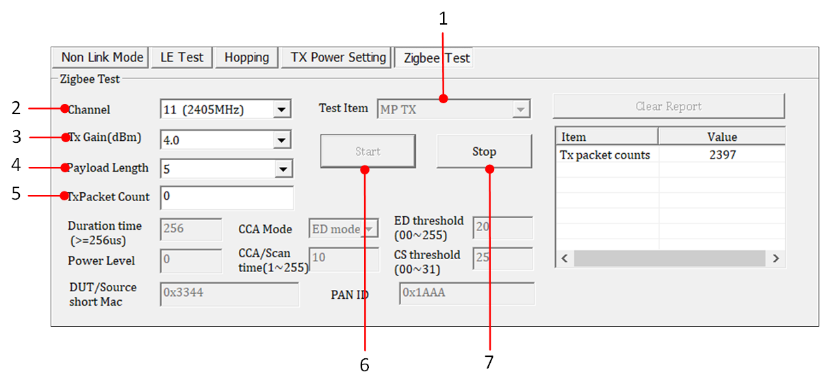
Zigbee MP TX Test
Zigbee PHY_TX-01(Modulation) Test
Used to test Output Power, frequency offset, the steps are as below.
Choose 'PHY_TX-01(Modulation)'.
Choose 'Channel'.
Choose 'Tx Gain', unit (dBm).
Set 'TxPacket Count'. 0: infinity.
Click Start button to start testing.
After testing, click Stop button.
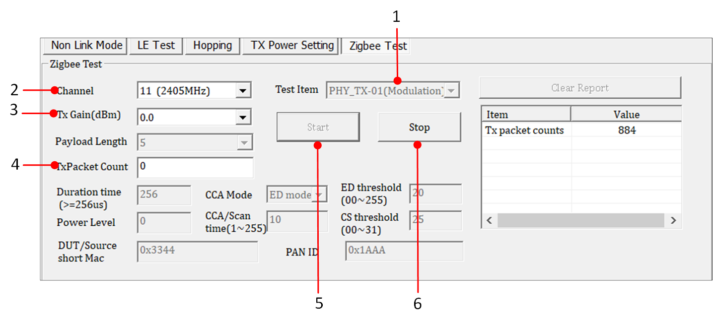
Zigbee PHY_TX-01 Test
Zigbee MP RX Test
Usually used to test PER and RSSI, the steps are as below.
Choose 'MP RX'.
Choose 'Channel'.
Click Start button and start to test.
After testing, click Stop button.
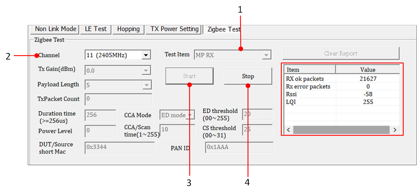
Zigbee MP RX Test
Note
The red rectangle of Zigbee MP RX Test shows correct received RX ok packets, RX error packets, RSSI, LQI.
Frequently Asked Questions
After clicking open in RFTestTool, the serial port can be opened, but there are some failed informations in the message box, and a message >>Device Open successfully..,but No MP function or Patch... appears. It is likely that the RF test patch has not been burned, as shown in the following figure:
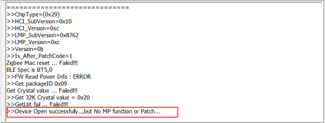
Open Error Messages
Contact Realtek Bluetooth FAE if any problem arises in the use of the test.