IEEE 802.15.4 MAC User Manual
The Realtek 802.15.4 MAC/PHY solution complies with IEEE 802.15.4-2015, designed for low-data-rate applications, such as home automation, industrial automation, and consumer electronics. Integrating baseband/MAC and 2.4 GHz RF transceiver with BLE support in a single SoC. The baseband/MAC block provides hardware architecture for both the MAC and PHY layers and consists of various components such as a TX/RX control module, a CSMA-CA controller, a security engine, and a digital signal processing module.
This document will explain the above section. Below are the supported features.
Supported Features
RF Analog Features
2.405~2.480 GHz operation in the ISM band.
Compliance with the IEEE 802.15.4-2015 specification.
Sensitivity of -99.5 dBm and maximum input level of 0 dBm.
Typical output power of 7.5 dBm and a 30 dB TX power control range.
Differential RF input/output and an integrated TX/RX switch.
An integrated low noise LNA, frequency synthesizer, and loop filter.
An integrated internal oscillator circuit.
High RSSI dynamic ranges.
MAC Features
Compliance with the IEEE 802.15.4-2015 specification.
Hardware CSMA-CA mechanism, automatic ACK response, and FCS check.
Functionally independent TX buffers, including transmit buffer and Enh-Ack buffer.
Hardware security engine (AES-128).
Support for the ED (Energy Detection) scan function.
Full support for the Zigbee 3.0 specification.
Full support for the Thread v1.3 specification.
Hardware Architecture
The IEEE 802.15.4 transceiver hardware architecture is as shown in Overall Structure Diagram, it is composed of six blocks:

Overall Structure Diagram
PHY Block
The PHY block is compliant with the IEEE 802.15.4 2.4 GHz ISM band standard. It implements data modulation/demodulation, energy detection, CCA for CSMA-CA, and RF control for channel selection and packet transmission/reception. It also provides RSSI and LQI for packet reception. The following sections will provide further introduction to ED Scan, CCA , as well as RSSI and LQI.
ED Scan
The ED scan measures peak RF power on a channel, helping PAN coordinators select channels. It involves multiple rounds, each scanning for 8 symbols and reporting results. The MAC stores peak values and issues an interrupt when done.
CCA
Clear Channel Assessment (CCA) detects if the current channel is occupied, implemented in the CSMA-CA algorithm. The PHY provides three CCA types: CS (Carrier Sense), ED (Energy Detection), and a combination of both.
CS mode (default) detects IEEE 802.15.4 2.4 GHz O-QPSK signals.
ED mode detects in-band signals, consuming more power. Set CCA to ED before sending packets and revert to CS after reading interrupt status.
Combined mode checks both CS and ED results, reporting a busy medium only if IEEE 802.15.4 signals with energy above the ED threshold are detected.
RSSI and LQI
The PHY block also provides both RSSI and LQI for each received packet.
RSSI: used to report the signal strength of a received packet.
LQI: used to report the link quality.
The MAC hardware automatically attaches both LQI and RSSI values to a received packet in the RX buffer every time a packet is received successfully.
Note
For more information about the RX buffer, please refer to Section RX Buffer.
MAC Block
This section provides a brief introduction to the IEEE 802.15.4 MAC layer. It mainly includes the TXMAC and RXMAC sections, as well as the MAC Timer and BT Clock Timer.
Note
It is recommended that users read the IEEE 802.15.4-2011/2015 specification for a more comprehensive understanding.
TXMAC
The TXMAC performs two main tasks that adhere to the IEEE 802.15.4 standard. These tasks are:
Automatic CSMA-CA and time alignments
-
TX buffer control
CSMA-CA
The timing relationship between the CCA (clear channel assessment) and packet transmission for the CSMA-CA algorithms is illustrated in Figure CSMA-CA.

CSMA-CA
Note
The backoff exponent (BE) is related to how many backoff periods a device shall wait before attempting to assess a channel.
This CSMA-CA algorithm is not used for the transmission of Imm-Ack frames and Enh-Ack frames. The CSMA-CA mechanism is applied only to the transmission of Normal buffer and Enh-Ack buffer.
Please reference Section 6.2.5.1 of IEEE 802.15.4-2015 Spec. for a detailed description of the CSMA-CA algorithm.
Hardware Auto-Retransmission
The TXMAC supports 'automatic retransmissions'. The explanation is as follows:
When the Ack Request bit in the Frame Control Field (FCF) is set, the receiver must send an acknowledgement (ACK).
If the ACK is not received, the TXMAC retransmits the packet until the maximum number of retransmissions (default 3) is reached.
For Data/Command frames with frame version 0 or 1, the TXMAC expects an Immediate Acknowledgement (Imm-Ack).
For frame version 2, it expects an Enhanced Acknowledgement (Enh-Ack).
The MAC layer firmware writes the packet into the TX buffer and ensures the MAC header is correct.
Transmission at Given Time
The TXMAC's 'transmission at given time' function allows scheduling packet transmissions, useful for routers sending packets to end devices that periodically sleep. This ensures packets are sent when the device is awake.
Differences from normal CSMA-CA transmission include:
No CSMA-CA mechanism or back-off delay.
No automatic retransmission if ACK is not received.
Optional clear channel assessment (CCA) before transmission.
Note
This function, described in IEEE 802.15.4-2015 Section 6.12.2, applies only to TX Normal buffer transmissions.
Enh-Ack Transmission
The RXMAC triggers the TXMAC to send an Imm-Ack frame for packets with frame version 0 or 1. For frame version 2, the MAC firmware sends an Enh-Ack frame via the Enh-Ack buffer, not the TX Normal buffer, to avoid conflicts. CSMA-CA for Enh-Ack transmission should be disabled for Enh-Ack frames.
An RX early interrupt can trigger when the RXMAC starts receiving a packet, allowing the MAC firmware to prepare an Enh-Ack frame. This frame is transmitted after the packet is fully received and passes the FCS check, following IFS timing rules in IEEE 802.15.4-2015 Section 6.2.4. The TXMAC mechanism ensures the Enh-Ack frame is transmitted at the appropriate time.
Timing of Enh-Ack Transmission Trigger in RX Early Interrupt shows the timing of the RX early interrupt, packet received interrupt, and Enh-Ack transmission. The MAC firmware prepares an Enh-Ack frame in the Enh-Ack buffer and triggers its transmission in the RX early interrupt handler. The delay includes the Enh-Ack timer and RX-to-TX Enh-Ack delay.

Timing of Enh-Ack Transmission Trigger in RX Early Interrupt
TXMAC Interrupts
The TXMAC can generate several different types of interrupts, including:
-
TX Normal Buffer transmission interrupt (txnif)This interrupt is issued when a packet in the TX Normal buffer transmission is triggered and the transmission is finished, regardless of whether it was successful or not.Transmission failure can be caused by a failed CSMA-CA (channel is busy) or reaching the maximum number of retransmission attempts.This interrupt is also issued when a transmission at a given time is triggered and completed.
-
TX Enh-Ack Buffer transmission interrupt (txg1if)This interrupt is issued when a packet in the Enh-Ack buffer transmission is finished, regardless of whether the transmission was successful or failed.The transmission can fail due to reasons such as CSMA-CA failure (channel is busy) or reaching the retransmission limit.
-
TX at given time error interrupt (txnterrif)If the given time TX timer (BT clock comparator) is enabled and the time period from the current BT time (clock) to the time scheduled for packet transmission is too short to allow the packet transmission process to complete, or if the time to trigger the given time transmission is reached but the packet transmission process fails to start due to a busy MAC state (for instance, the MAC is transmitting or receiving a packet), or the PHY is not granted access to the MAC at that instant, this interrupt is asserted.
Note
These interrupts can be used by the MAC firmware to perform various tasks, such as updating the state of the MAC or preparing for the transmission of another packet.
RXMAC
The RXMAC includes the following modules and functions:
The RXMAC receives packet data from the RX PHY baseband, performs FCS checking, and parses frame type and address recognition. It stores packets in 144-byte buffer and filters packets per IEEE 802.15.4-2015 rules. If checks pass, packets are stored in the RX buffer.
RX Filter
The RXMAC receives packet data from the RX PHY baseband and performs filtering. It checks the preamble and delimiter for IEEE 802.15.4 compliance, performs address recognition, and filters packets per Section 6.7.2 of IEEE 802.15.4-2015. Valid packets passing FCS checks are stored in the RX buffer.
Auto Imm-Ack
The RXMAC automatically replies with an ACK frame by default for valid, non-broadcast frames. If the Frame Type indicates a Data frame or MAC command with Frame Version 0 or 1 and 'ACK Request' is set to 1, the RXMAC instructs the TXMAC to send an Imm-Ack frame with the same sequence number as the received frame, maintaining the AIFS time requirement per IEEE 802.15.4-2015 Section 6.2.4. This auto-acknowledgement feature is enabled by default.
For frames with Frame Version 0b10, the RXMAC does not send Imm-Ack or Enh-Ack frames automatically. Instead, the MAC firmware generates the Enh-Ack frame in the Enh-Ack buffer and controls the TXMAC to transmit it, as Enh-Ack frames may contain IEs, frame payloads, and require encryption, which are managed by the MAC sublayer firmware.
Source Address Match Filter
The Source Address Match Filter provides 'Frame Pending' info to the TXMAC for Imm-Ack frames. It compares the 'Source PAN ID' and 'Source Address' of incoming MAC Data/Command frames with filter entries. The TXMAC sets the 'Frame Pending' bit based on this comparison. The MAC firmware manages address entries, enabling them when data is pending for a specific device and disabling them when no data is pending.
Address entries can be:
Short address: 16-bit PAN ID and 16-bit short address.
Extended address: 64-bit extended address.
Note
The filter supports up to 32 short addresses or 16 extended addresses, sharing the same register space. Extended and short address entries sharing registers should not be enabled simultaneously, managed by the MAC firmware to avoid conflicts.
RXMAC Interrupts
The RXMAC generates the following interrupts:
-
Packet received interrupt (rxif)This interrupt is triggered when an incoming packet becomes available in the RX buffer, meaning it has passed both the RX filter and the FCS check.
-
RX early interrupt (rxelyif)This interrupt triggers when an incoming frame's MAC header, including the 'Auxiliary Security Header' is processed.It occurs before the 'Packet Received' interrupt, allowing MAC firmware to prepare a response, such as generating an Enh-Ack frame or determining the Frame Pending bit for Imm-Ack.This RX Early interrupt gives the MAC firmware more time to prepare the Enh-Ack frame, especially for secure frames, ensuring timely transmission.It applies to frames other than ACK frames if their frame version is 2 or if the frame is secured.
-
Security interrupt (secif)When the 'Auxiliary Security Header' of an encrypted frame is received, the RXMAC does not inform the security engine directly.Instead, it triggers a security interrupt to the CPU. The MAC firmware can then choose whether to use the security engine to decrypt the incoming frame or to disregard the decryption.After this, a Packet Received interrupt will be issued once the frame reception is complete and has passed the FCS check.The process of decrypting a received secure frame can be disabled. If this packet receive decryption process is disabled, the Security interrupt will not be triggered upon receipt of a secure frame.
MAC Timer
MAC Timer has the following features:
The MAC includes an internal 16-bit timer that counts down with a period of half a symbol time (8 microseconds).
The MAC timer can be started by setting the initial countdown value. The timer then counts down from this value with the MAC time of half-symbol (8us) period. When the countdown reaches zero, a MAC timer interrupt is generated.
The MAC timer can also be configured as a free-running timer. When the MAC timer is in free-running mode, the MAC timer interrupt will be generated whenever the countdown value reaches 0, and the counter value will be reloaded as 0xFFFF.
BT Clock Timer
The BT clock, used by the BLE MAC, is a free-running clock with a 1 us tick time. It consists of a 28-bit up-counter that is ticked with a unit of half BT slot time (312.5 us), combined with a 10-bit down-counter that is ticked with a unit of 1us to count a BT slot time (625 us).
The IEEE 802.15.4 MAC shares this clock for PHY access conflict resolution. Key uses include:
RX Timestamp: Latches the BT clock at the first symbol of the MAC header received.
TX Timestamp: Latches the BT clock at the first symbol of the MAC header transmitted.
TX at a given time: Uses a BT clock comparator to trigger normal buffer transmission.
PHY Arbitration Request: Uses the BT clock to determine the anchor point for PHY accessibility.
BT Clock Comparator: Four comparators monitor the BT clock and issue interrupts when matched.
The BT clock value latch function helps the MAC firmware obtain the current BT clock value.
Memory Block
The memory block is a SRAM block that is used to implement the buffers for packet transmission and reception, as well as the security key buffer for packet encryption or decryption.
Includes the following modules:
TX Buffers
The TXMAC retrieves data to transmit from two different TX buffers.
Normal buffer: Transmission of Data and Command frames.
Enh-Ack buffer: Transmission of Enh-Ack frames.
Depending on the specific conditions of the transmission, a specific buffer is selected. All TX buffers are 128 bytes long, which allows them to hold one IEEE 802.15.4 MAC packet at a time.
RX Buffer
A RX buffer is composed of 144-byte buffer to store incoming packets.
When the RXMAC is receiving a new incoming frame and stores it into the RX buffer, the byte of 'Frame Length' is extracted from the PHY header and be pasted to the front of the MAC frame. This facilitates the MAC firmware to decode the frame correctly with correct frame length information. Moreover, other LQI, RSSI and RX Timestamp information are attached to the tail of the received frame data.
Security Key Buffer
Security key buffer holds the corresponding key of each buffer ciphering.
Security Engine Block
The Security module provides the security engine for the MAC, which is compatible to IEEE 802.15.4-2006 (and after). IEEE 802.15.4 Spec uses the AES-CCM * algorithm to provides the packet authentication and encryption. The AES-CCM* algorithm combines the AES-CBC and AES-CTR algorithm.
Note
Please reference to the Section 7.3 and Annex B of IEEE 802.15.4-2011 Spec for the details of this security operation.
In addition to MAC layer security requirements, the security engine also provides a method called 'upper-layer security' for network or application layer use. The AES engine embedded in the MAC can be used as a stand-alone co-processor, too.
The features of this Security Engine Block are listed below:
Transmit encryption and receive decryption.
Support all security levels cipher modes defined in IEEE 802.15.4-2006/2011.
Security Level |
Cipher Mode |
Data Encryption |
MIC Length |
|---|---|---|---|
0 |
None |
No |
None |
1 |
AES-MIC-32 |
No |
32-bits |
2 |
AES-MIC-64 |
No |
64-bits |
3 |
AES-MIC-128 |
No |
128-bits |
4 |
AES-ENC |
Yes |
None |
5 |
AES-ENC-MIC32 |
Yes |
32-bits |
6 |
AES-ENC-MIC64 |
Yes |
64-bits |
7 |
AES-ENC-MI128 |
Yes |
128-bits |
-
64 bytes Security Key buffer is composed of four 128-bits security keys.
RX buffer, Normal buffer, and Enh-Ack buffer have their own keys.
The fourth key space is reserved for further use.
Security of application and network layers can be achieved using this security engine.
The Security Engine Block will be introduced from five aspects:
TX Packet Cipher Encryption
For packet encryption, the security engine fetches data from TX buffer, parses it for Header Length and Frame Length, and performs encryption. Encrypted data and MIC overwrite the original data in TX buffer. Depending on the security level, a MIC may be generated and appended to the packet tail, increasing Frame Length. The PHY header's 7-bit Frame Length field limits the packet size to 127 bytes, including a 2-byte FCS. Thus, payload plus MIC must not exceed 125 bytes. MAC firmware checks packet length before encryption. The following is a list of Max packet length for different cipher modes.
Cipher mode |
MIC length (bytes) |
Maximum packet length (bytes) |
|---|---|---|
AES-ENC |
0 |
125 |
AES-MIC32 / AES-ENC-MIC32 |
4 |
121 |
AES-MIC64 / AES-ENC-MIC64 |
8 |
117 |
AES-MIC64 / AES-ENC-MIC64 |
16 |
109 |
RX Packet Cipher Decryption
For a received secure frame decryption, the security engine will get the Frame Length and fetch packet data from RX buffer, get the header length information from the register to perform packet cipher decryption. The RXMAC will parse the incoming packet header and then update the header length of the incoming packet in the register. The security engine will write decrypted data back to RX buffer, which will overwrite the original un-decrypted data.
Upper Layer Cipher Encryption and Decryption
Upper layer (or application) also can use this security engine to do packet data encryption or decryption. The packet to be encrypted or decrypted should be put into the TX Normal buffer. The Header Length and Frame Length in the TX buffer should be filled according to the format definition. The encryption or decryption output data will be written back to the TX Normal buffer. Which will overwrite the original data. The upper layer cipher encryption process is the same as the encryption process of a secure frame transmission.
As the Figure Upper Layer Cipher Decryption Process below. The Header Length field in TX buffer presents the length of data those are not going to be decrypted. The Frame Length field in TX buffer presents the total length of encrypted packet, includes MIC.
There are 2 cases for the setting of the Frame Length value:
If the MIC length is 0 (cipher mode without MIC): the Frame Length filed should be filled as 'Header Length' + encrypted data length.
If the MIC length is not 0 (cipher mode with MIC): the Frame Length filed should be filled as 'Header Length' + encrypted data length + 2.
The decrypted packet data will be written back to the TX Normal buffer.

Upper Layer Cipher Decryption Process
Secure Frame Transmission Flow
For a secure frame transmission, the MAC firmware can just prepare the un-encrypted packet data in TX buffer, the key in Security buffer and fill the nonce in registers. And then let the TXMAC co-work with security engine to do the secure packet transmission.
Secure Frame Receiving Flow
When a secure frame is received, the MAC firmware can decide whether to use the security engine to decrypt the received packet in RX buffer directly. The received secure frame decryption process flow and the interaction between the RXMAC, security engine and MAC firmware is illustrated below.
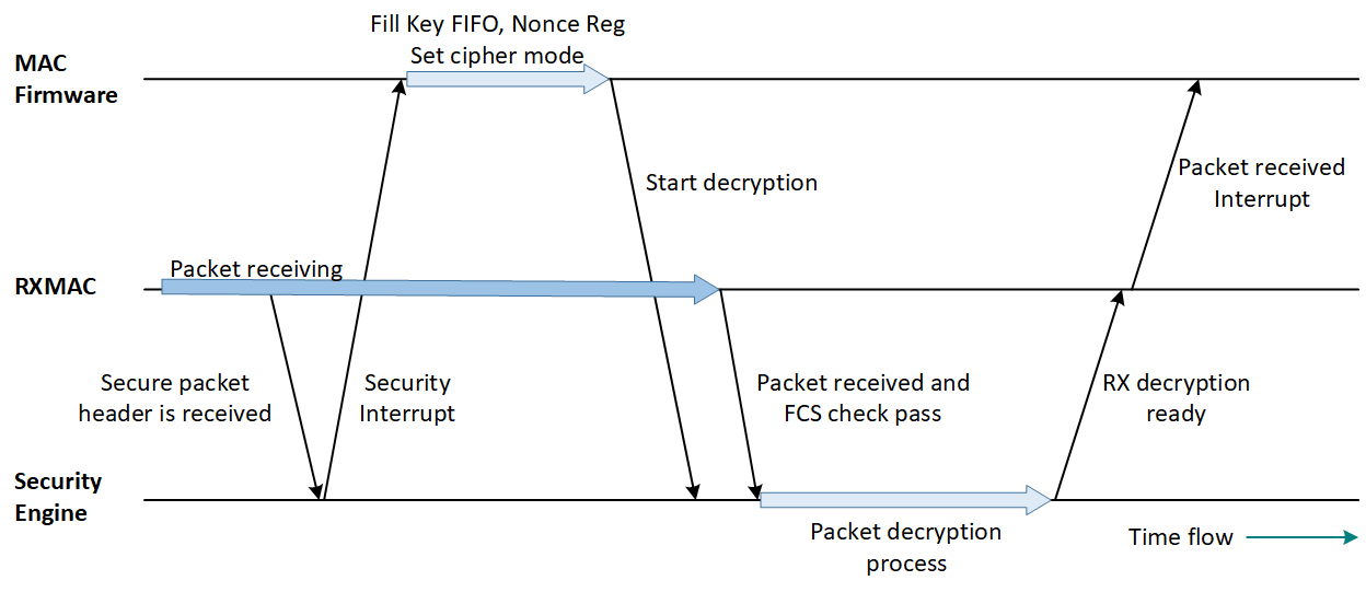
Secure Frame Receiving and Decryption Flow
Note
once the secure frame receiving is finished, the RXMAC will notify the Security Engine.
The Security Engine may be pending and waiting for the firmware to trigger the packet decryption or ignore the packet decryption.
When the Security Engine finishes the packet decryption, it will notify the RXMAC.
Then the RXMAC will notify the firmware via a packet received interrupt.
PHY Arbitration
Due to hardware cost and flexibility, the IEEE 802.15.4 MAC shares the same PHY with BLE using TDMA.
Devices may need to run BLE and IEEE 802.15.4 protocols (e.g., Zigbee) concurrently, but the PHY can only be used by one at a time. A dedicated hardware handles PHY arbitration to switch accessibility. BLE events (e.g., advertising, connection) are scheduled periodically, and the PHY arbitration hardware manages access conflicts. This hardware also arbitrates between BLE events and IEEE 802.15.4 MAC by adding a PHY arbitration entry for IEEE 802.15.4 MAC. The IEEE 802.15.4 MAC can access the PHY only when granted, and if revoked, the MAC stops immediately, issuing a PHY grant interrupt to the CPU.
Firmware Operation
Basic Operations
Initialization
Basic MAC Initialization Flow is to initialize the MAC to be an end device of a PAN. Device is in the Non-beacon enabled mode. RF at default channel 11 (2405 MHz). Supports Zigbee and Thread v1.2 protocol stack.
Steps |
Description |
FW Operation |
|---|---|---|
1 |
Initialize mac_attribute_t structure with default value. |
Call |
2 |
Enable MAC clock. |
Call |
3 |
Initialize mac layer with attributes. |
|
4 |
Register mac callback function. |
Change Channel Procedure
Set RF operation channel in 2.4 GHz ISM band. The operating frequency is divided into 16 channels. The RF frequency of each channel is illustrated below.

IEEE 802.15.4 PHY Channel in 2.4G ISM Band
Steps |
Description |
FW Operation |
|---|---|---|
1 |
Set channel. |
Call |
Get Current BT Clock
The MAC firmware may need to get current BT clock during the following process.
Make a time delay or timeout to wait for HW operation to complete.
To determine the anchor point of a PHY arbitration request.
To schedule a given time packet transmission.
To let the MAC firmware get the current BT clock correctly (no transient value), the MAC hardware provides a BT clock latch function to assist the firmware to read current BT clock.
Steps |
Description |
FW Operation |
|---|---|---|
1 |
Get Current BT Clock. |
Call
|
Set BT Clock Comparator Interrupt
There are total 4 BT clock comparators (timer) are implemented in the MAC hardware which can be used to issue an interrupt at a specified time (BT clock). The MAC firmware can get a synchronization with the MAC activate via BT clock comparator interrupts. For example, to schedule a CSL transmission, the MAC firmware can arrange a BT clock comparator interrupt to trigger the preparation of a given time transmission.
Steps |
Description |
FW Operation |
|---|---|---|
1 |
Set BT Clock Comparator Interrupt. |
Call
|
Register a Source Address Match Filter Entry
If the device works as a PAN router. Its child device can poll pending frames by sending a Data Request command frame to the router. The router should set the FP in FCH as 1 in the Imm-Ack if it has a frame is pending for that child device. In this scenario, to let the TXMAC can determine the FP bit value when it is sending the Imm-Ack frame. The MAC firmware should register the child device's address to the Source Address Match Filter if it has a frame pending for that child device.
Steps |
Description |
FW Operation |
|---|---|---|
1 |
Add a short address and panid pair or an extended address match entry of Source Address Match Filter. |
|
ED (Energy Detection) Scan
To set up a PAN, the PAN coordinator normally will take a channel survey to pick a relatively cleaner channel to build the PAN. The ED scan is one of the methods to perform a channel survey.
Steps |
Description |
FW Operation |
|---|---|---|
1 |
Set RF channel. |
Set the RF channel for the ED Scan will be performed on. The flow to set up the RF channel is described in Section Change Channel Procedure. |
2 |
Start the ED scan procedure. |
|
Typical TX Operations
The TX PHY will automatically generate the preamble and Start-of-Frame delimiter fields when transmitting. Additionally, the TXMAC can generate any padding (if needed) and the CRC, if configured to do so. The MAC firmware must write all other frame fields into the TX buffer for transmission operation.
Transmit Packet in Normal Buffer
To send a packet in Normal Buffer, the flow is described in the following table.
Steps |
Description |
FW Operation |
|---|---|---|
1 |
Fill in Normal buffer with the packet to send. |
|
2 |
Trigger the transmission. |
Call
|
3 |
Wait TX Normal Buffer interrupt and check TX status. |
Check TX status by Call |
Transmit Packet with Security Encryption
To send a secured packet TX buffer, there are several steps to follow:
Steps |
Description |
FW Operation |
|---|---|---|
Load TX buffer with the packet to be send |
Firmware should fill the packet data into one of the two TX buffers that the user wants to send.
|
|
2 |
Load the nonce. |
Call |
3 |
Fill key memory. |
Call |
4 |
Configure the cipher mode. |
Call
|
5 |
Trigger encryption and TX. |
Call
|
6 |
Wait TX Normal buffer interrupt and check TX status. |
Call |
Transmit Packet in Normal Buffer with CCA/ED Mode
To send a packet in Normal buffer with CCA/ED mode or a combination of CS and ED modes, the flow basically is the same as the flow described in the Section Transmit Packet in Normal Buffer. The only difference is to configure the CCA mode for the CSMA-CA of packets transmission.
Steps |
Description |
FW Operation |
|---|---|---|
1 |
Fill in Normal buffer with the packet to send. |
|
2 |
Set CCA mode. |
Call
|
3 |
Wait TX Normal buffer interrupt and check TX status. |
Call |
CCA mode |
cca_mode filed value |
Explanation |
|---|---|---|
ED mode |
1 |
CCA reports the channel is busy if the ED scan result is over the threshold setting. |
CS mode |
2 |
CCA reports the channel is busy if the CS detection result over the threshold setting. |
ED or CS combination mode |
3 |
CCA reports the channel is busy when either ED scan or CS detection reports the channel is busy (result over the threshold). |
ED or CS combination mode |
4 |
CCA reports the channel is busy when both ED scan and CS detection report the channel is busy. |
Transmit Enh-Ack in Enh-Ack Buffer
When a Data frame or MAC command frame with its frame version is 2 is received and the acknowledgement is required, an Enh-Ack frame should be sent to the transmitter side as the acknowledgement. The MAC firmware is responsible to generate the Enh-Ack frame and send it through the TX Enh-Ack buffer. After the receiving frame transmission is end, this Enh-Ack frame should be sent in an AIFS period. So the Enh-Ack transmission procedure normally be starts in the RX early interrupt handler. That gain the MAC firmware can have more time to prepare the Enh-Ack frame and have it transmitted in time.
Steps |
Description |
FW Operation |
|---|---|---|
1 |
Fill in TX Enh-Ack buffer with the packet to send. |
Call
|
2 |
Set Security enable. |
|
3 |
Trigger the transmission. |
|
Transmit Packet in Normal Buffer with at Given Time
The transmit packet at a given time function normally is used to implement the CSL transmission mechanism defined in the IEEE 802.15.4 - 2015 Spec. This CSL transmission mechanism will according to the RX timestamp of the received packet with a CSL IE from its associated child device to decide when to start the packet transmission. Please note this transmit packet at a given time function only can be performed for Normal buffer transmission.
Steps |
Description |
FW Operation |
|---|---|---|
1 |
Fill in Normal buffer with the packet to send. |
|
2 |
Perform upper layer encryption. |
If this is a secure packet transmission, that's this packet is going to be ciphered before its transmission.
|
3 |
Trigger the |
|
4 |
Wait TX Normal buffer interrupt or TX at given time error interrupt. |
|
Typical RX Operations
The RX PHY filters all incoming signals and tracks the synchronization symbols. When the preamble of an IEEE 802.15.4 packet is found, the packet is demodulated and stored in the RX buffer. At the same time, the RXMAC starts calculating the frame FCS byte by byte and checking after received a whole packet. The RXMAC filters the MAC header and skips those packets not being sent to its own addresses. If the frame version of the packet is 0 or 1 and it is accepted, and it needs an acknowledgement, the RXMAC will inform the TXMAC to send an Imm-ACK automatically. If the frame version of the accepted packet is 2 and it needs an acknowledgement, the MAC firmware is responsible to send the Enh-Ack.
Receive Packet in RX Buffer
Figure RX Buffer format is shown below:
'Frame Length' (in bytes) field indicates the packet length which includes the lengths of the header, the payload, and FCS (2 bytes). But it does not include LQI (1 byte), RSSI (2 byte), RX Timestamp (2 or 4 bytes) and Superframe Count (3 bytes).
When a packet passes the baseband filtering (preamble and delimiter), it goes into the RXMAC. The RX filter of the RXMAC performs several levels of the packet filtering. Default mode is address-recognition mode, which can filter those packets not being sent to this device.
When a received packet passes the RX filter and it has the correct FCS, the packet received interrupt will be issued.

RX Buffer format
Steps |
Description |
FW Operation |
|---|---|---|
1 |
Read RX buffer |
Call |
2 |
Send Enh-Ack frame(for received packet with frame version 2 only). |
|
Upper-Layer-Cipher Operations
The security engine can be used for upper layer packet ciphering. For an upper layer packet encryption or decryption, this packet should be filled into the TX Normal buffer first. And then set up the cipher mode, nonce and key. Then trigger the security engine to perform the ciphering. The encrypted or decrypted data will be written back to the TX Normal buffer. The TX Normal buffer interrupt will be asserted to notify the firmware once the packet cipher is done. This upper layer cipher flow is similar to the flow for transmitting a packet with security encryption. Just the ciphered packet will not be transmitted to the air.
Upper-Layer-Cipher Encryption
Here are the steps for using TX Normal buffer, to perform the Upper-Layer-cipher encryption:
Steps |
Description |
FW Operation |
|---|---|---|
1 |
Load the packet to be encrypted into TX Normal buffer. |
The packet data format should follow the TX buffer format, in which:
|
2 |
Load the nonce. |
Call |
3 |
Fill key memory. |
Call |
4 |
Configure the cipher mode. |
Call |
5 |
Trigger the Upper-Layer-Cipher encryption. |
Call |
Security Level |
Cipher Mode |
Model value |
|---|---|---|
1 |
AES-MIC-32 |
4 |
2 |
AES-MIC-64 |
3 |
3 |
AES-MIC-128 |
2 |
4 |
AES-ENC |
1 |
5 |
AES-ENC-MIC32 |
4 |
6 |
AES-ENC-MIC64 |
3 |
7 |
AES-ENC-MIC128 |
2 |
Note
After the packet cipher process, the MIC (4, 8, or 16 bytes) shall be appended to packet payload and the frame length is updated automatically.
The selected cipher mode is shown in TX Buffer content before and after the encryption below.

TX Buffer content before and after the encryption
Upper-Layer-Cipher Decryption
Here are the flow for using TX Normal buffer to perform the Upper-Layer-cipher decryption.
Steps |
Description |
FW Operation |
|---|---|---|
1 |
Load the packet to be decrypted into TX Normal buffer. |
The packet data format should follow the TX buffer format definition, refer to Upper Layer Cipher Decryption Process, in which:
|
2 |
Load the nonce. |
Call |
3 |
Fill key memory. |
Call |
4 |
Configure the cipher mode. |
Call |
5 |
Trigger the decryption. |
Call |
6 |
Read decrypted packet. |
Once the decryption process is finished, the decrypted packet can be read from the TX Normal buffer.
|
Sample Projects
This module provides examples for user reference: IEEE 802.15.4 Simple TRX.
References
IEEE 802.15.4-2006.
IEEE 802.15.4-2011.
IEEE 802.15.4-2015.