IR Transmit
This example demonstrates the use of the IR transmit function.
Data is sent using the IR peripheral to implement the IR transmit function, and the IR transmit waveform is observed using a logic analyzer.
Requirements
The sample supports the following development kits:
Hardware Platforms |
Board Name |
|---|---|
RTL8752H HDK |
RTL8752H EVB |
For more requirements, please refer to Quick Start.
Wiring
Connect the IR transmit pin P2_5 to the logic analyzer.
Building and Downloading
This sample can be found in the SDK folder:
Project file: board\evb\io_sample\IR\Tx\mdk
Project file: board\evb\io_sample\IR\Tx\gcc
Please follow these steps to build and run the example:
Open sample project file.
To build the target, follow the steps listed on the Generating App Image in Quick Start.
After a successful compilation, the app bin
app_MP_xxx.binwill be generated in the directorymdk\binorgcc\bin.To download app bin into EVB board, follow the steps listed on the MP Tool Download in Quick Start.
Press reset button on EVB board and it will start running.
Experimental Verification
Observe the IR TX waveform within the logic analyzer.
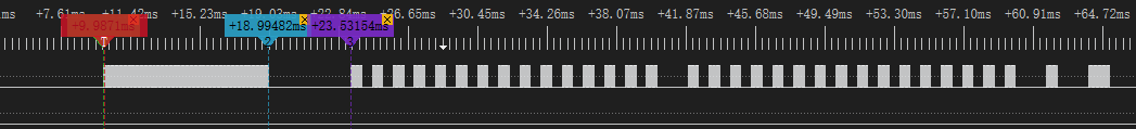
IR Transmit Waveform
Code Overview
This chapter will be introduced according to the following several parts:
Peripheral initialization will be introduced in chapter Initialization.
Functional implementation after initialization will be introduced in chapter Function Implementation.
Source Code Directory
Project directory:
sdk\board\evb\io_sample\IR\TxSource code directory:
sdk\src\sample\io_sample\IR\Tx
Source files are currently categorized into several groups as below.
└── Project: ir_tx
    └── secure_only_app
        └── include
            ├── app_define.h
            └── rom_uuid.h
        ├── cmsis                    includes CMSIS header files and startup files
            ├── overlay_mgr.c
            ├── system_rtl876x.c
            └── startup_rtl876x.s
        ├── lib                      includes all binary symbol files that user application is built on
            ├── rtl8752h_sdk.lib
            ├── gap_utils.lib
            ├── ROM.lib
            └── adc.lib
        ├── peripheral               includes all peripheral drivers and module code used by the application
            ├── rtl876x_rcc.c
            ├── rtl876x_pinmux.c
            ├── rtl876x_nvic.c
            └── rtl876x_ir.c
        ├── profile
        └── app                      includes the ble_peripheral user application implementation
            └── main.c
Initialization
When the EVB reset is initiated, the main function is executed, following these steps:
int main(void)
{
    extern uint32_t random_seed_value;
    srand(random_seed_value);
    __enable_irq();

    ir_demo();

    ...
}
In ir_demo, it includes PAD/PINMUX settings and the initialization process of the IR peripheral.
void ir_demo(void)
{
    ...
    board_ir_init();
    driver_ir_init(IR_TxData.CarrierFreq);
    ...
}
board_ir_init is for PAD and PINMUX settings and includes the following steps:
Configure PAD: set pins, PINMUX mode, PowerOn, internal pull-none and output low.
Configure PINMUX: assign pins to IRDA_TX function.
driver_ir_init is for IR peripheral initialization and includes the following steps:
Enable RCC clock.
Set the IR transmit frequency to 38 kHz.
Set the IR carrier duty cycle to 1/2.
Set the IR to transmit mode.
Set the IR transmission data will not be inverted.
Set the IR transmit FIFO threshold to 2.
Configure the IR to send FIFO data count less than the set send threshold interrupt
IR_INT_TF_LEVEL.void driver_ir_init(uint32_t vFreq) { /* Enable ir clock */ RCC_PeriphClockCmd(APBPeriph_IR, APBPeriph_IR_CLOCK, ENABLE); /* Initialize ir */ IR_InitTypeDef IR_InitStruct; IR_StructInit(&IR_InitStruct); IR_InitStruct.IR_Freq = vFreq; IR_InitStruct.IR_DutyCycle = 2; /* !< 1/2 duty cycle */ IR_InitStruct.IR_Mode = IR_MODE_TX; IR_InitStruct.IR_TxInverse = IR_TX_DATA_NORMAL; IR_InitStruct.IR_TxFIFOThrLevel = IR_TX_FIFO_THR_LEVEL; IR_Init(&IR_InitStruct); /* Enable IR threshold interrupt. when TX FIFO offset <= threshold value, trigger interrupt*/ IR_INTConfig(IR_INT_TF_LEVEL, ENABLE); /* Configure nvic */ NVIC_InitTypeDef NVIC_InitStruct; NVIC_InitStruct.NVIC_IRQChannel = IR_IRQn; NVIC_InitStruct.NVIC_IRQChannelPriority = 3; NVIC_InitStruct.NVIC_IRQChannelCmd = ENABLE; NVIC_Init(&NVIC_InitStruct); }
Functional Implementation
Define IR transmission data in
ir_demo. Data with carrier is represented by performing a bitwise OR operation with the number of carriers and 0x80000000, while data without carrier is represented by performing a bitwise OR operation with the number of carriers and 0x00000000.Execute the
IR_SendBuf()function to start filling the IR transmission FIFO with transmission data; enable the IR peripheral transmission function.-
Record the number of data items that have been transmitted.
void ir_demo(void)
{
    /* Data to send */
    IR_TxData.CarrierFreq = 38000;
    IR_TxData.DataLen = 67 + 1; //2+64+1;
    IR_TxData.DataBuf[0] =  0x80000000 | 0x156; //342 about 9ms
    IR_TxData.DataBuf[1] =  0x00000000 | 0xAB; //171 about 4.5ms
    for (uint16_t i = 2; i < IR_TxData.DataLen - 1;)
    {
        IR_TxData.DataBuf[i] =  0x80000000 | 0x15; //21  about 560us
        IR_TxData.DataBuf[i + 1] =  0x00000000 | 0x15; //21  about 565us
        i += 2;
    }
    IR_TxData.DataBuf[30] =  0x80000000 | 0x15; //21  about 560us
    IR_TxData.DataBuf[31] =  0x00000000 | 0x40; //64  about 1690us
    IR_TxData.DataBuf[62] =  0x80000000 | 0x15; //21  about 560us
    IR_TxData.DataBuf[63] =  0x00000000 | 0x40; //64  about 1690us
    IR_TxData.DataBuf[64] =  0x80000000 | 0x15; //21  about 560us
    IR_TxData.DataBuf[65] =  0x00000000 | 0x40; //64  about 1690us
    IR_TxData.DataBuf[66] =  0x80000000 | 0x15; //21  about 560us
    IR_TxData.DataBuf[IR_TxData.DataLen - 1] =  0x80000000 | 0x15;

    ...

    /* Start to send data. */
    IR_SendBuf(IR_TxData.DataBuf, IR_TX_FIFO_SIZE, DISABLE);
    IR_Cmd(IR_MODE_TX, ENABLE);
    /* Record number which has been sent */
    IR_TX_Count = IR_TX_FIFO_SIZE;
}
-
When the number of data items in the IR transmission FIFO is less than the set transmission threshold (set to 2 in this example), trigger the
IR_INT_TF_LEVELinterrupt to enter the interrupt handler functionIR_Handler.Mask the
IR_INT_TF_LEVELinterrupt.Since the IR transmission data may be large (greater than the IR TX FIFO depth), it needs to be sent in batches.
If the remaining number of transmission data items is greater than the size of the transmission FIFO, fill the IR transmission FIFO with (IR_TX_FIFO_SIZE - IR_TX_FIFO_THR_LEVEL) data items and transmit, indicating that the remaining data volume is still greater than the IR TX FIFO depth.
Otherwise, if the remaining number of transmission data items is greater than 0, fill the IR transmission FIFO with the remaining data, indicating that the remaining data volume is less than the IR TX FIFO depth, i.e., transmitting the last batch of data.
Otherwise, if there is no remaining data, disable the
IR_INT_TF_LEVELinterrupt, indicating that all IR data has been transmitted.Unmask the
IR_INT_TF_LEVELinterrupt.
void IR_Handler(void)
{
    /* Get IR interrupt status */
    ITStatus int_status = IR_GetINTStatus(IR_INT_TF_LEVEL);

    /* Mask IR interrupt */
    IR_MaskINTConfig(IR_INT_TF_LEVEL, ENABLE);

    /* Continue to send by interrupt */
    if (int_status == SET)
    {
        /* The remaining data is larger than the TX FIFO length */
        if ((IR_TxData.DataLen - IR_TX_Count) >= IR_TX_FIFO_SIZE)
        {
            IR_SendBuf(IR_TxData.DataBuf + IR_TX_Count, (IR_TX_FIFO_SIZE - IR_TX_FIFO_THR_LEVEL), DISABLE);
            IR_TX_Count += (IR_TX_FIFO_SIZE - IR_TX_FIFO_THR_LEVEL);

            /* Clear threshold interrupt */
            IR_ClearINTPendingBit(IR_INT_TF_LEVEL_CLR);
        }
        else if ((IR_TxData.DataLen - IR_TX_Count) > 0)
        {
            /* The remaining data is less than the TX FIFO length */

            /*  Configure TX threshold level to zero and trigger interrupt when TX FIFO is empty */
            IR_SetTxThreshold(0);
            IR_SendBuf(IR_TxData.DataBuf + IR_TX_Count, IR_TxData.DataLen - IR_TX_Count, DISABLE);
            IR_TX_Count += (IR_TxData.DataLen - IR_TX_Count);

            /* Clear threshold interrupt */
            IR_ClearINTPendingBit(IR_INT_TF_LEVEL_CLR);
        }
        else
        {
            /* Tx completed */
            /* Disable IR tx empty interrupt */
            IR_INTConfig(IR_INT_TF_LEVEL, DISABLE);
            IR_TX_Count = 0;

            /* Clear threshold interrupt */
            IR_ClearINTPendingBit(IR_INT_TF_LEVEL_CLR);
        }
    }

    /* Unmask IR interrupt */
    IR_MaskINTConfig(IR_INT_TF_LEVEL, DISABLE);
}
See Also
相关 API Reference 请查看: