PWM
This example demonstrates the use of the TIM peripheral to output PWM waveforms, and it can achieve the following functions:
Using TIM2 to output PWM with a period of 1s and a duty cycle of 50%, with P0_1 as the PWM output.
Implementing complementary PWM output with P0_2 as PWM_P output and P2_2 as PWM_N output. When the dead zone is set, PWM_P and PWM_N will be delayed by one dead zone duration when outputting high levels. The macro
PWM_DEAD_ZONE_CLOCK_SOURCE_5Mcan be configured to switch the dead zone clock source to 5M.Implementing PWM complementary Bypass function with P0_2 as PWM_P output and P2_2 as PWM_N output. When the Bypass function is set by configuring the macro
PWM_DEAD_ZONE_BYPASS, PWM_P and PWM_N output waveforms are completely complementary, with no dead zone generated.The macro
PWM_COMPL_OUTPUT_EM_STOP_TESTcan be configured to implement the PWM output emergency stop function.
Requirements
The sample supports the following development kits:
Hardware Platforms |
Board Name |
|---|---|
RTL8752H HDK |
RTL8752H EVB |
For more requirements, please refer to Quick Start.
Wiring
Connect P0_1 (PWM output), P0_2 (PWM_P), and P2_2 (PWM_N) to the logic analyzer to observe the waveform.
Configurations
The configurable macros for this example are as follows:
PWM_DEAD_ZONE_CLOCK_SOURCE_5M: Configuring this macro adjusts the clock source of the PWM complementary waveform output dead zone to 5M.PWM_DEAD_ZONE_BYPASS: Configuring this macro adjusts the output PWM complementary waveform to be fully complementary, with no dead zone.PWM_COMPL_OUTPUT_EM_STOP_TEST: Configuring this macro implements the emergency stop function for PWM output.
Building and Downloading
This sample can be found in the SDK folder:
Project file: board\evb\io_sample\TIM\PWM\mdk
Project file: board\evb\io_sample\TIM\PWM\gcc
Please follow these steps to build and run the example:
Open sample project file.
To build the target, follow the steps listed on the Generating App Image in Quick Start.
After a successful compilation, the app bin
app_MP_xxx.binwill be generated in the directorymdk\binorgcc\bin.To download app bin into EVB board, follow the steps listed on the MP Tool Download in Quick Start.
Press reset button on EVB board and it will start running.
Experimental Verification
Using a logic analyzer, you can observe that P0_1 outputs a PWM wave with a period of 1 second and a duty cycle of 50%. P0_2, as PWM_P, outputs a waveform that is delayed by the deadzone time at the rising edge relative to P0_1. P2_2 outputs a PWM wave as PWM_N, which is out of phase with P0_2.
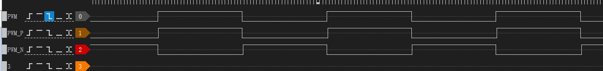
PWM Output Waveform
Zooming in on the waveform above, when the macro
PWM_DEAD_ZONE_CLOCK_SOURCE_5Mis not enabled, the dead zone length is 5ms. When the macroPWM_DEAD_ZONE_CLOCK_SOURCE_5Mis enabled, the dead zone length becomes 4us.
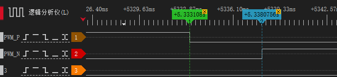
PWM Dead Zone Waveform
When the macro
PWM_DEAD_ZONE_BYPASSis enabled, the complementary PWM waveform output shows no dead zone, resulting in a completely complementary waveform.

PWM Bypass Output Waveform
When the macro
PWM_COMPL_OUTPUT_EM_STOP_TESTis enabled, the complementary PWM waveform output periodically pauses, indicating an emergency stop.

PWM Emergency Stop Output Waveform
Code Overview
This chapter will be introduced according to the following several parts:
Peripheral initialization will be introduced in chapter Initialization.
Functional implementation after initialization will be introduced in chapter Function Implementation.
Source Code Directory
Project directory:
sdk\board\evb\io_sample\TIM\PWMSource code directory:
sdk\src\sample\io_sample\TIM\PWM
Source files are currently categorized into several groups as below.
└── Project: pwm
    └── secure_only_app
        └── include
            ├── app_define.h
            └── rom_uuid.h
        ├── cmsis                    includes CMSIS header files and startup files
            ├── overlay_mgr.c
            ├── system_rtl876x.c
            └── startup_rtl876x.s
        ├── lib                      includes all binary symbol files that user application is built on
            ├── rtl8752h_sdk.lib
            ├── gap_utils.lib
            └── ROM.lib
        ├── peripheral               includes all peripheral drivers and module code used by the application
            ├── rtl876x_rcc.c
            ├── rtl876x_pinmux.c
            ├── rtl876x_nvic.c
            └── rtl876x_tim.c
        ├── profile
        └── app                      includes the ble_peripheral user application implementation
            └── main.c
Initialization
When the EVB resets, the main function is executed, following this process:
int main(void)
{
    extern uint32_t random_seed_value;
    srand(random_seed_value);
    pwm_demo();

    ...
}
In pwm_demo, it includes PAD/PINMUX settings and TIM peripheral initialization.
void pwm_demo(void)
{
    /* Configure PAD and pinmux firstly! */
    board_pwm_init();

    /* Initialize TIM peripheral */
    driver_pwm_init();
}
board_pwm_init is the PAD/PINMUX settings, including the following steps:
Configure PAD: set pin, PINMUX mode, PowerOn, internal pull-none, output high.
Configure PINMUX: configure the pin for TIM_PWM2, PWM2_P, and PWM2_N functions respectively.
#define PWM_OUT_PIN_PINMUX      TIM_PWM2
#define PWM_OUT_P_PIN_PINMUX    PWM2_P
#define PWM_OUT_N_PIN_PINMUX    PWM2_N

void board_pwm_init(void)
{
    Pad_Config(PWM_OUT_PIN, PAD_PINMUX_MODE, PAD_IS_PWRON, PAD_PULL_NONE, PAD_OUT_ENABLE, PAD_OUT_HIGH);
    Pad_Config(PWM_OUT_P_PIN, PAD_PINMUX_MODE, PAD_IS_PWRON, PAD_PULL_NONE, PAD_OUT_ENABLE, PAD_OUT_HIGH);
    Pad_Config(PWM_OUT_N_PIN, PAD_PINMUX_MODE, PAD_IS_PWRON, PAD_PULL_NONE, PAD_OUT_ENABLE, PAD_OUT_HIGH);
    Pinmux_Config(PWM_OUT_PIN, PWM_OUT_PIN_PINMUX);
    Pinmux_Config(PWM_OUT_P_PIN, PWM_OUT_P_PIN_PINMUX);
    Pinmux_Config(PWM_OUT_N_PIN, PWM_OUT_N_PIN_PINMUX);
}
driver_pwm_init is the initialization for the TIM peripheral, including the following steps:
Enable the RCC clock.
Configure TIM to a user-defined mode.
Enable the PWM output function of TIM, configure the output period and duty cycle.
Configure the PWM emergency stop function, complementary pin output levels.
Enable the PWM dead zone function, set the size of the dead zone.
If the macro
PWM_DEAD_ZONE_CLOCK_SOURCE_5Mis enabled, executeRCC_ClockSrc5MCmd()to enable the 5M clock, and executeTIM_PWMChangeDZClockSrc()to switch the clock source of the dead zone.If the macro
PWM_DEAD_ZONE_BYPASSis enabled, executeTIM_PWMDZBypassCmd()to enable the bypass function.Enable TIM2 and start outputting the PWM waveform.
void driver_pwm_init(void)
{
    RCC_PeriphClockCmd(APBPeriph_TIMER, APBPeriph_TIMER_CLOCK, ENABLE);
#if PWM_DEAD_ZONE_CLOCK_SOURCE_5M
    RCC_ClockSrc5MCmd();
#endif

    TIM_TimeBaseInitTypeDef TIM_InitStruct;

    TIM_StructInit(&TIM_InitStruct);
    TIM_InitStruct.TIM_Mode             = TIM_Mode_UserDefine;
    TIM_InitStruct.TIM_PWM_En           = PWM_ENABLE;
    TIM_InitStruct.TIM_PWM_High_Count   = PWM_HIGH_COUNT;
    TIM_InitStruct.TIM_PWM_Low_Count    = PWM_LOW_COUNT;
    TIM_InitStruct.PWM_Stop_State_P     = PWM_STOP_AT_HIGH;
    TIM_InitStruct.PWM_Stop_State_N     = PWM_STOP_AT_LOW;
    TIM_InitStruct.PWMDeadZone_En       = DEADZONE_ENABLE;  //enable to use pwn p/n output
    TIM_InitStruct.PWM_Deazone_Size     = PWM_DEAD_ZONE_SIZE;
    TIM_TimeBaseInit(TIM2, &TIM_InitStruct);

#if PWM_DEAD_ZONE_CLOCK_SOURCE_5M
    TIM_PWMChangeDZClockSrc((PWM_TypeDef *)(&TIMER_PWM2_CR), ENABLE);
#endif

    TIM_Cmd(TIM2, ENABLE);

#if PWM_DEAD_ZONE_BYPASS
    TIM_PWMDZBypassCmd((PWM_TypeDef *)(&TIMER_PWM2_CR), ENABLE);
#endif
}
Functional Implementation
After the initialization phase is completed, the PWM output waveform can be observed in the logic analyzer.
If the macro PWM_COMPL_OUTPUT_EM_STOP_TEST is enabled, the function TIM_PWMComplOutputEMCmd() will be executed within the main function, repeatedly enabling and disabling the PWM output emergency stop function.
int main(void)
{
    ...

    while (1)
    {
#if PWM_COMPL_OUTPUT_EM_STOP_TEST
        platform_delay_ms(2000);
        //PWM complementary output emergency stop.
        TIM_PWMComplOutputEMCmd(PWM2, ENABLE);
        platform_delay_ms(2000);
        //Resume PWM complementary output.
        TIM_PWMComplOutputEMCmd(PWM2, DISABLE);
#else

#endif
    }
}
See Also
Please refer to the relevant API Reference: