Timer Interrupt
This example uses TIM to achieve a 1-second timer function.
To facilitate observation, connect P0_1 and LED0.
When the timer expires, it triggers an interrupt. In the interrupt handler function, P0_1 is toggled to change the GPIO output polarity, making LED0 blink every second.
Requirements
The sample supports the following development kits:
Hardware Platforms |
Board Name |
|---|---|
RTL8752H HDK |
RTL8752H EVB |
For more requirements, please refer to Quick Start.
Wiring
Connect P0_1 and LED0 light.
The LED driver circuit is shown in the figure below.
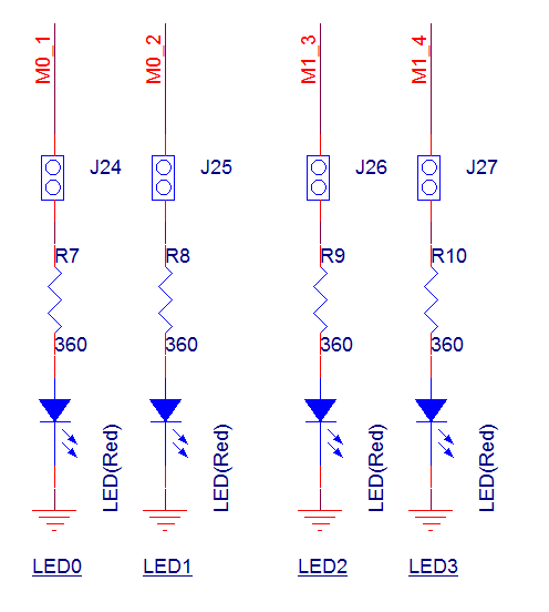
LED driver circuit diagram
Building and Downloading
This sample can be found in the SDK folder:
Project file: board\evb\io_sample\TIM\Timer_interrupt\mdk
Project file: board\evb\io_sample\TIM\Timer_interrupt\gcc
Please follow these steps to build and run the example:
Open sample project file.
To build the target, follow the steps listed on the Generating App Image in Quick Start.
After a successful compilation, the app bin
app_MP_xxx.binwill be generated in the directorymdk\binorgcc\bin.To download app bin into EVB board, follow the steps listed on the MP Tool Download in Quick Start.
Press reset button on EVB board and it will start running.
Experimental Verification
When P0_1 is connected to LED0, observe LED0 flashing once every second.
Code Overview
This chapter will be introduced according to the following several parts:
Peripheral initialization will be introduced in chapter Initialization.
Functional implementation after initialization will be introduced in chapter Function Implementation.
Source Code Directory
Project directory:
sdk\board\evb\io_sample\TIM\Timer_interruptSource code directory:
sdk\src\sample\io_sample\TIM\Timer_interrupt
Source files are currently categorized into several groups as below.
└── Project: timer_interrupt
    └── secure_only_app
        └── include
            ├── app_define.h
            └── rom_uuid.h
        ├── cmsis                    includes CMSIS header files and startup files
            ├── overlay_mgr.c
            ├── system_rtl876x.c
            └── startup_rtl876x.s
        ├── lib                      includes all binary symbol files that user application is built on
            ├── rtl8752h_sdk.lib
            ├── gap_utils.lib
            └── ROM.lib
        ├── peripheral               includes all peripheral drivers and module code used by the application
            ├── rtl876x_rcc.c
            ├── rtl876x_pinmux.c
            ├── rtl876x_nvic.c
            ├── rtl876x_gdma.c
            └── rtl876x_adc.c
        ├── profile
        └── app                      includes the ble_peripheral user application implementation
            └── main.c
Initialization
When the EVB reset, the "main" function is executed, following these steps:
int main(void)
{
    extern uint32_t random_seed_value;
    srand(random_seed_value);
    __enable_irq();

    tim_demo();

    while (1)
    {

    }
}
In tim_demo, it includes PAD/PINMUX settings, GPIO, and TIM peripheral initialization.
void tim_demo(void)
{
    timer_demo();
}

void timer_demo(void)
{
    LED_Status = 0;
    board_gpio_init();
    driver_gpio_init();
    driver_timer_init();
}
board_gpio_init is PAD/PINMUX settings related to GPIO, including the following processes:
Configure PAD: Set pin, PINMUX mode, PowerOn, internal pull-none, output low.
Configure PINMUX: Configure pin for DWGPIO function.
void board_gpio_init(void)
{
    Pad_Config(GPIO_OUTPUT_PIN_0, PAD_PINMUX_MODE, PAD_IS_PWRON, PAD_PULL_NONE, PAD_OUT_ENABLE, PAD_OUT_LOW);
    Pinmux_Config(GPIO_OUTPUT_PIN_0, DWGPIO);
}
driver_gpio_init is GPIO peripheral initialization, including the following processes:
Enable RCC clock.
Set GPIO pin to output mode, disable interrupt.
Set GPIO pin output low.
void driver_gpio_init(void)
{
    /* Initialize GPIO peripheral */
    RCC_PeriphClockCmd(APBPeriph_GPIO, APBPeriph_GPIO_CLOCK, ENABLE);

    GPIO_InitTypeDef GPIO_InitStruct;
    GPIO_StructInit(&GPIO_InitStruct);
    GPIO_InitStruct.GPIO_Pin    = GPIO_PIN_OUTPUT;
    GPIO_InitStruct.GPIO_Mode   = GPIO_Mode_OUT;
    GPIO_InitStruct.GPIO_ITCmd  = DISABLE;
    GPIO_Init(&GPIO_InitStruct);
    GPIO_ResetBits(GPIO_PIN_OUTPUT);
}
driver_timer_init is the initialization of the TIM peripheral, including the following steps:
Enable the RCC clock.
Configure TIM to user-defined mode.
Disable the PWM output function and set the TIM period.
Configure and enable the TIM IRQ channel.
Configure TIM interrupt and enable TIM.
void driver_timer_init(void)
{
    RCC_PeriphClockCmd(APBPeriph_TIMER, APBPeriph_TIMER_CLOCK, ENABLE);

    TIM_TimeBaseInitTypeDef TIM_InitStruct;
    TIM_StructInit(&TIM_InitStruct);

    TIM_InitStruct.TIM_PWM_En = PWM_DISABLE;
    TIM_InitStruct.TIM_Period = TIMER_PERIOD ;
    TIM_InitStruct.TIM_Mode = TIM_Mode_UserDefine;
    TIM_TimeBaseInit(TIMER_NUM, &TIM_InitStruct);

    /*  Enable TIMER IRQ  */
    NVIC_InitTypeDef NVIC_InitStruct;
    NVIC_InitStruct.NVIC_IRQChannel = TIMER_IRQN;
    NVIC_InitStruct.NVIC_IRQChannelPriority = 3;
    NVIC_InitStruct.NVIC_IRQChannelCmd = ENABLE;
    NVIC_Init(&NVIC_InitStruct);

    TIM_ClearINT(TIMER_NUM);
    TIM_INTConfig(TIMER_NUM, ENABLE);
    TIM_Cmd(TIMER_NUM, ENABLE);

}
Functional Implementation
When the TIM timer expires, it triggers an interrupt and enters the interrupt handler function Timer4_Handler.
Clear the TIM interrupt and disable TIM.
Check the current LED status and toggle the GPIO output level.
Re-enable TIM.
void Timer4_Handler(void)
{

    TIM_ClearINT(TIM4);
    TIM_Cmd(TIM4, DISABLE);
    if (!LED_Status)
    {
        GPIO_SetBits(GPIO_PIN_OUTPUT);
        LED_Status = 1;
    }
    else
    {
        GPIO_ResetBits(GPIO_PIN_OUTPUT);
        LED_Status = 0;
    }
    //Add user code here
    TIM_Cmd(TIM4, ENABLE);

}
See Also
Please refer to the relevant API Reference: