I2C Master Write
This sample code guide is written to help users easily and completely understand I2C sample. This sample demonstrates I2C master write data function in polling mode and GDMA mode. In this sample, I2C is configured as the master. The chip writes some data to I2C slave.
Requirements
For hardware requirements, please refer to the Requirements.
Wiring
Connect P0_0 to the SCL of the I2C slave, connect P0_1 to the SDA of the I2C slave, need to connect 2.2k pull-up resistor.
The hardware connection of I2C sample code is shown in the figure below.
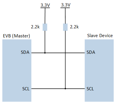
I2C Sample Code Hardware Connection Diagram
Configurations
-
The following macros can be configured to modify pin definitions.
#define PIN_I2C1_SCL P0_0#define PIN_I2C1_SDA P0_1
-
The entry function is as follows, call this function in
main()to run this sample code. For more details, please refer to the Initialization.i2c_mw_demo();
Building and Downloading
For building and downloading, please refer to the Building and Downloading.
Experimental Verification
Press the Reset button on the EVB, the master device sends 12 bytes of data to slave, the I2C slave will receive data 0xaa, 0xbb, 0x66, 0x68, 0x77, 0x88, 0xaa, 0xbb, 0x66, 0x68, 0x77, 0x88.
Code Overview
This section introduces the code and process description for initialization and corresponding function implementation in the sample.
Source Code Directory
For project directory, please refer to Source Code Directory.
Source code directory:
sdk\src\sample\io_demo\i2c\master_write\i2c_mw_demo.c.
Initialization
The initialization flow for peripherals can refer to Initialization Flow.
I2C master mode initialization flow is shown in the following figure.
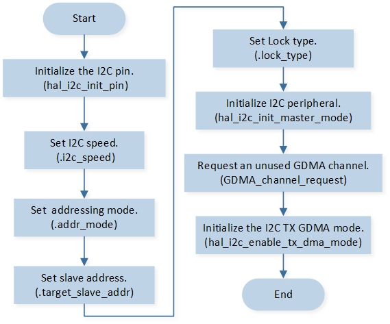
I2C Master Mode Initialization Flow Chart
-
Call
hal_i2c_init_pin()to initialize the pin.hal_i2c_init_pin(I2C_ID, PIN_I2C1_SCL, PIN_I2C1_SDA);
-
Initialize the I2C peripheral:
Define the
T_I2C_MASTER_CONFIGtypei2c_config.Modify the
i2c_configparameters as needed. The I2C initialization parameter configuration is shown in the table below.Call
hal_i2c_init_master_mode()to initialize the I2C peripheral.
I2C Initialization Parameters I2C Hardware Parameters
Setting in the
i2c_configI2C
Clock
400000
Address Mode (7bits/10bits Mode)
Slave Address
0x08
Lock Type
Call
GDMA_channel_requestto request an unused GDMA channel.Call
hal_i2c_enable_tx_dma_mode()to initialize the I2C TX GDMA mode.
Functional Implementation
Master Write By Polling Mode
The master call hal_i2c_master_write(), sends the data in I2C_WriteBuf to the slave by polling mode.
uint8_t I2C_WriteBuf[16] = {0xaa, 0xbb, 0x66, 0x68, 0x77, 0x88};

/* Use polling mode to write */
T_I2C_STATUS ret = hal_i2c_master_write(I2C_ID, ADDR, I2C_WriteBuf, 6);

if (ret != I2C_STATUS_OK)
{
   IO_PRINT_ERROR1("i2c_mw_demo: Polling mode send failed %d", ret);
}
Master Write By GDMA Mode
The master call hal_i2c_master_write_by_dma(), sends the data in I2C_WriteBufDMA to the slave by GDMA mode.
uint16_t I2C_WriteBufDMA[16] = {0xaa, 0xbb, 0x66, 0x68, 0x77, 0x88};

/* Use dma mode to write */
ret = hal_i2c_master_write_by_dma(I2C_ID, ADDR, I2C_WriteBufDMA, 6);

if (ret != I2C_STATUS_OK)
{
   IO_PRINT_ERROR1("i2c_mw_demo: DMA mode send failed %d", ret);
}