Charging Case
This document focuses on the design spec of the charging case demo. It is written to help users easily and completely understand the code flow of the application. The article is roughly divided into sections on hardware configuration, environment setup, testing procedures, software framework, and common issues. For detailed content, please refer to the main text below.
Requirements
The sample supports the following development kits:
Hardware Platforms |
Board Name |
Build Target |
|---|---|---|
RTL87x3E HDK |
RTL87x3E EVB |
|
RTL87x3D HDK |
RTL87x3D EVB |
|
RTL87x3EP HDK |
RTL87x3EP EVB |
|
Note
To purchase EVB, please visit https://www.realmcu.com/en/Home/Shop.
When built for an xxx_16M_xxx build target, the sample is configured to build and run with a 16M flash map.
To quickly set up the development environment, please refer to the detailed instructions provided in Quick Start.
Touchpad and LCD
The default supported touch screen and LCD models in the application are listed in the following table:
Board Name |
Touchpad |
LCD |
|---|---|---|
RTL87x3E EVB |
CST816D |
ST77916 |
RTL87x3D EVB |
CHSC6417 |
ST7801 |
RTL87x3EP EVB |
CHSC6417 |
ST7801 |
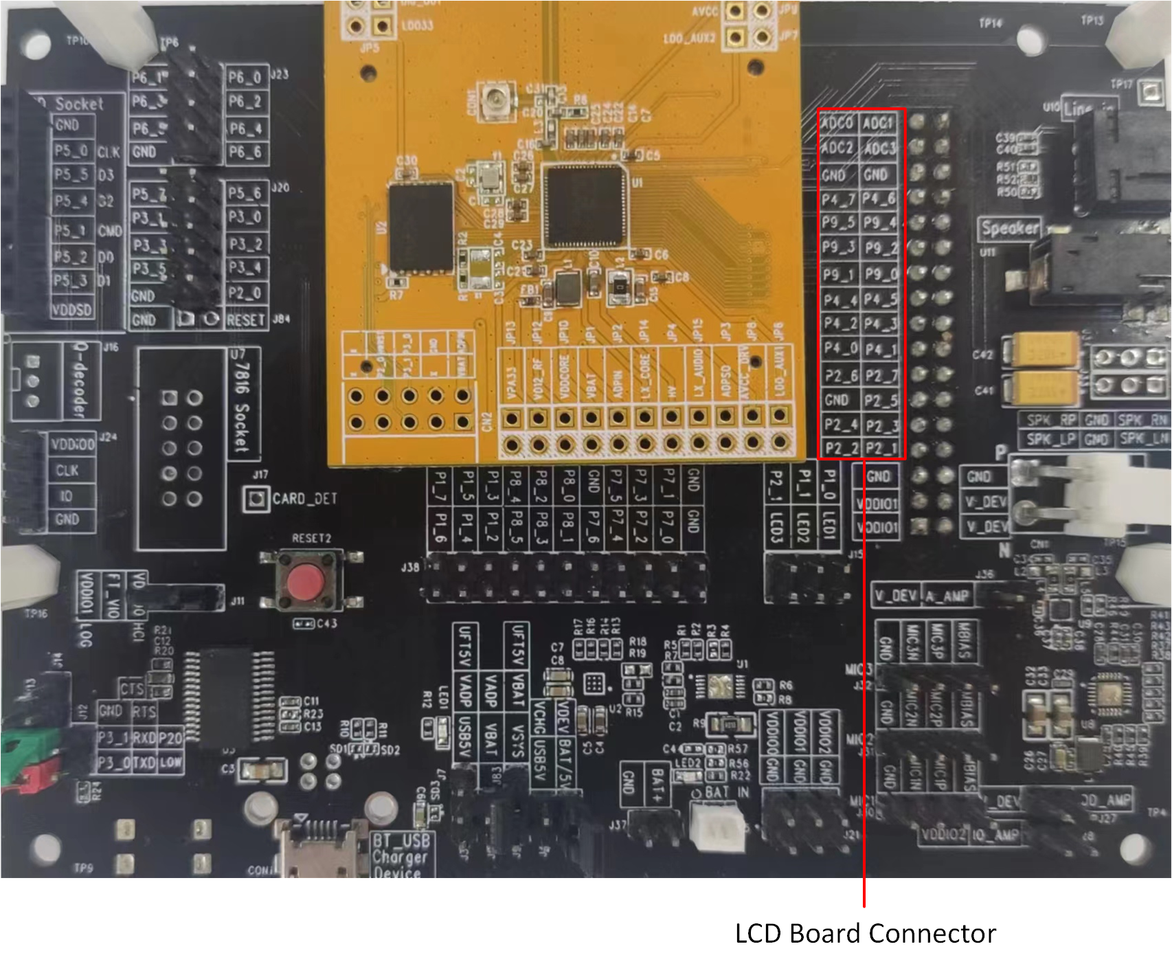
For convenience in testing the touchpad and LCD, we have developed an adapter board. Simply plug the adapter board into the card slot of the EVB, and it is possible to test and use the touchpad and LCD.
RTL87x3E EVB
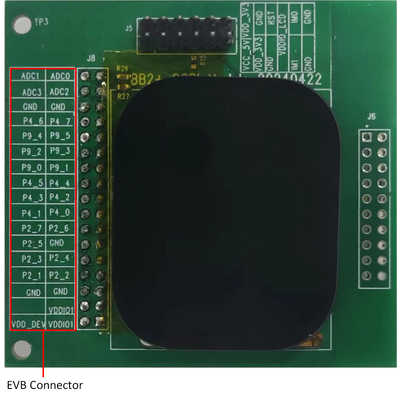
The touch screen and LCD model is connected to the EVB via an adapter board. Simply plug the adapter board into J35 of the EVB:
The mapping relationship between the touchpad/LCD and EVB pins is shown in the following table:
Touchpad and LCD |
EVB |
|---|---|
TP_SCL |
ADC_0 |
TP_SDA |
ADC_1 |
TP_INT |
ADC_2 |
TP_RST |
ADC_3 |
SPI_CLK |
P9_4 |
SPI_SIO3 |
P9_5 |
SPI_CSN |
P9_2 |
SPI_SIO0 |
P9_3 |
SPI_SIO2 |
P9_0 |
SPI_SIO1 |
P9_1 |
LCD_RST |
P4_4 |
TE |
P2_2 |
LCD_BL_EN |
P2_3 |
VDD_DEV |
VDD_DEV |
GND |
GND |
RTL87x3EP EVB
Compared to RTL87x3E EVB, the RTL87x3EP supports another set of touch and LCD screens, but simply plugging the adapter board into J35 of the EVB will also work:
RTL87x3EP GUI EVB
Screen
The mapping relationship between the touchpad/LCD and EVB pins is shown in the following table:
Touchpad and LCD |
EVB |
|---|---|
TP_SCL |
ADC_0 |
TP_SDA |
ADC_1 |
TP_INT |
ADC_2 |
TP_RST |
ADC_3 |
SPI_CLK |
P9_4 |
SPI_SIO3 |
P9_5 |
SPI_CSN |
P9_2 |
SPI_SIO0 |
P9_3 |
SPI_SIO2 |
P9_0 |
SPI_SIO1 |
P9_1 |
P4_5 |
NC |
LCD_RST |
P4_4 |
TE |
P4_5 |
LCD_BL_EN |
P2_3 |
VDD_DEV |
VDD_DEV |
GND |
GND |
RTL87x3D EVB
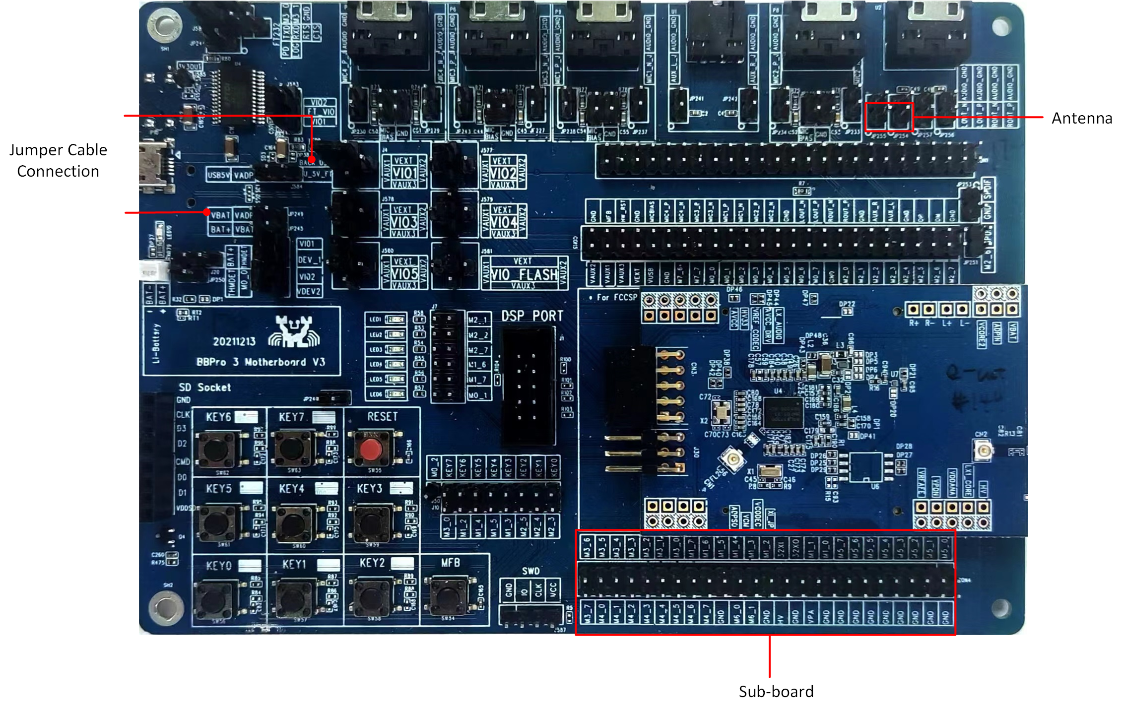
RTL87x3D GUI EVB
For the Antenna marking, users need to connect an antenna to the designated port. As for the Subboard, it should be inserted into the corresponding socket on the main board. Additionally, the Jumper Cable Connection is required to provide USB power. Users need to connect jumper cables accordingly to establish the connection and support the USB power supply:
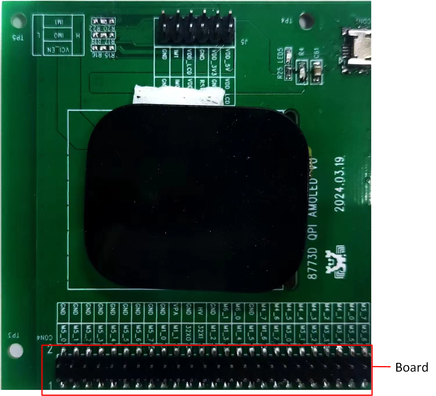
Sub Board
The subboard should be plugged into the corresponding subboard position on the main board.
The mapping relationship between the touchpad/LCD and EVB pins is shown in the following table:
Touchpad and LCD |
EVB |
|---|---|
TP_SCL |
M4_5 |
TP_SDA |
M4_6 |
TP_INT |
M4_4 |
TP_RST |
M4_2 |
SPI_CLK |
M3_2 |
SPI_SIO3 |
M3_7 |
SPI_CSN |
M3_3 |
SPI_SIO0 |
M3_4 |
SPI_SIO2 |
M3_6 |
SPI_SIO1 |
M3_5 |
LCD_RST |
M5_2 |
TE |
M5_4 |
LCD_BL_EN |
M4_1 |
VCI_EN |
M5_5 |
GND |
GND |
VDD_DEV |
VBAT |
VDDIO1 |
VIO2_VEXT |
Tools
SDK provides an image conversion tool that facilitates the conversion of images, such as JPG, PNG, and BMP, into burnable BIN files. The image conversion tool provided by the SDK is located in the sdk\tool path.
To learn more about the tool’s usage guidelines, please refer to Image Convert Tool.
Files
The previous chapter introduces the steps for converting image resources. For font resource conversion, consult with FAE to address the requirements. Once both the image and font resources have been generated as binary files, the packaging tool can be used to convert them into the final userdata binary file.
The GUI package tool provided by the SDK is located in the sdk\tool\Gadgets\gui_package_tool path. Select the folder according to the IC type:
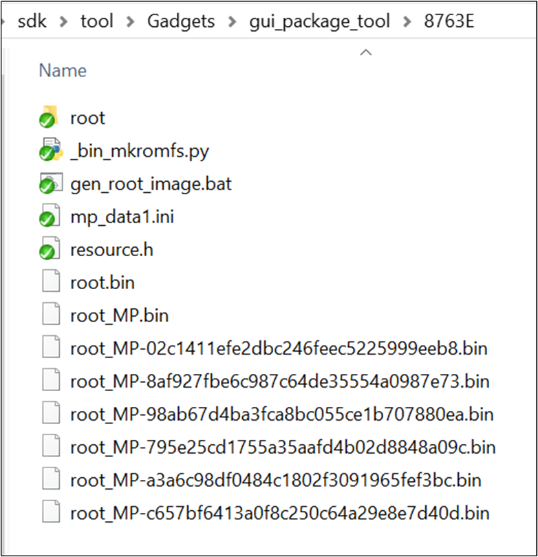
GUI Package Tool
Place the bin files of the images and fonts into the root folder.
Execute the
gen_root_image.bat.A userdata bin file will be generated in the current path. Please select the file with the suffix and random number.
Note
While packing the userdata file, a resource.h file will also be generated. This file is used to generate the APP bin file, and the APP code can use the addresses of the images or fonts in this file to index the related resources.
Configurations
The charging case demo is developed based on bt_audio_trx. It uses some features present in bt_audio_trx. The features used in the charging case demo are defined in the macro F_APP_CHARGE_CASE_DEMO_SUPPORT, which is located in app_flags.h. Set F_APP_CHARGE_CASE_DEMO_SUPPORT to 1, build, and generate the charging case demo bin.
The functionalities included in the charging case can be enabled or disabled through the following macro definitions:
#if F_APP_CHARGE_CASE_DEMO_SUPPORT
#undef F_SOURCE_PLAY_SUPPORT
#define F_SOURCE_PLAY_SUPPORT                   1
#undef F_APP_VOICE_NREC_SUPPORT
#define F_APP_VOICE_NREC_SUPPORT                0
#undef F_APP_LE_AUDIO_INITIATOR_SUPPORT
#define F_APP_LE_AUDIO_INITIATOR_SUPPORT        1
#undef F_APP_DISABLE_NOTIFICATION_SUPPORT
#define F_APP_DISABLE_NOTIFICATION_SUPPORT      1
#undef F_APP_BT_AUDIO_USB_DEMO_SUPPORT
#define F_APP_BT_AUDIO_USB_DEMO_SUPPORT         1
#undef TRANSMIT_CLIENT_SUPPORT
#define TRANSMIT_CLIENT_SUPPORT                 1
#undef F_APP_CHARGING_CASE_CMD_SUPPORT
#define F_APP_CHARGING_CASE_CMD_SUPPORT         1
#undef F_APP_CHARGING_CASE_CMD_TEST_SUPPORT
#define F_APP_CHARGING_CASE_CMD_TEST_SUPPORT    0
#undef F_APP_SD_CARD_PLAY
#define F_APP_SD_CARD_PLAY                      0
#if F_APP_BT_AUDIO_USB_DEMO_SUPPORT
#define F_APP_FWK_PIPE_DEMO_SUPPORT             1
#else
#define F_APP_FWK_PIPE_DEMO_SUPPORT             0
#endif

#if F_APP_SD_CARD_PLAY
#define F_APP_SD_CARD_LOCALPLAY                 1
#endif

#undef F_APP_FINDMY_FEATURE_SUPPORT
#define F_APP_FINDMY_FEATURE_SUPPORT            0

#undef F_APP_ENABLE_TWO_ONE_WIRE_UART
#define F_APP_ENABLE_TWO_ONE_WIRE_UART          0

#if (TARGET_RTL8763EW_VC || TARGET_RTL8763EWE_VP || TARGET_RTL8763EWE || TARGET_RTL8773DO || (TARGET_RTL87X3EP && !TARGET_4M))
#undef F_APP_GUI_SUPPORT
#define F_APP_GUI_SUPPORT                       1
#undef ENABLE_PSRAM_FOR_LCD
#define ENABLE_PSRAM_FOR_LCD                    0
//#define  ENABLE_RTK_GUI_SCRIPT_AS_A_APP
#endif

#endif /* end of F_APP_CHARGE_CASE_DEMO_SUPPORT */
Due to limitations in resources such as DSP and RAM, we are unable to enable all functions. Some functions are disabled by default. In cases where resources are sufficient, customers can enable or disable functions based on their product requirements through switch macro definitions.
Building and Downloading
This sample can be found under sdk\board\evb\bt_audio_trx in the SDK folder structure.
Take the project rtl87x3e_bt_audio_trx.uvprojx and target bt_audio_trx_16M_lea_dual_bank0 as an example. To build and run the sample with the Keil development environment, follow the steps listed below:
Open the project
rtl87x3e_bt_audio_trx.uvprojx.Set
F_APP_CHARGE_CASE_DEMO_SUPPORTinapp_flags.hto 1, and other macros below shall be set to 0:/** * NOTE: Only one demo support flag shall be set to 1 */ #define F_APP_BT_AUDIO_TRANSMITTER_DEMO_SUPPORT 0 #define F_APP_BT_AUDIO_RECEIVER_DEMO_SUPPORT 0 #define F_APP_BT_AUDIO_TRANSCEIVER_DEMO_SUPPORT 0 #define F_APP_BT_AUDIO_TRANSMITTER_MP3_DEMO_SUPPORT 0 #define F_APP_CHARGE_CASE_DEMO_SUPPORT 1 #define F_APP_DASHBOARD_DEMO_SUPPORT 0
Choose the build target
bt_audio_trx_16M_lea_dual_bank0: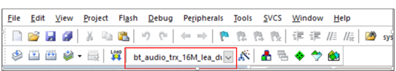
Build Target
Build the target:
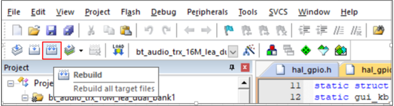
Building
After a successful build, the APP bin file
bt_audio_trx_bank0_MP-v0.0.0.0-xxx.binwill be generated in the directorybin\rtl87x3e\flash_16M_dualbank\bank0.Download the generated APP bin
bt_audio_trx_bank0_MP-v0.0.0.0-xxx.bininto the EVB board: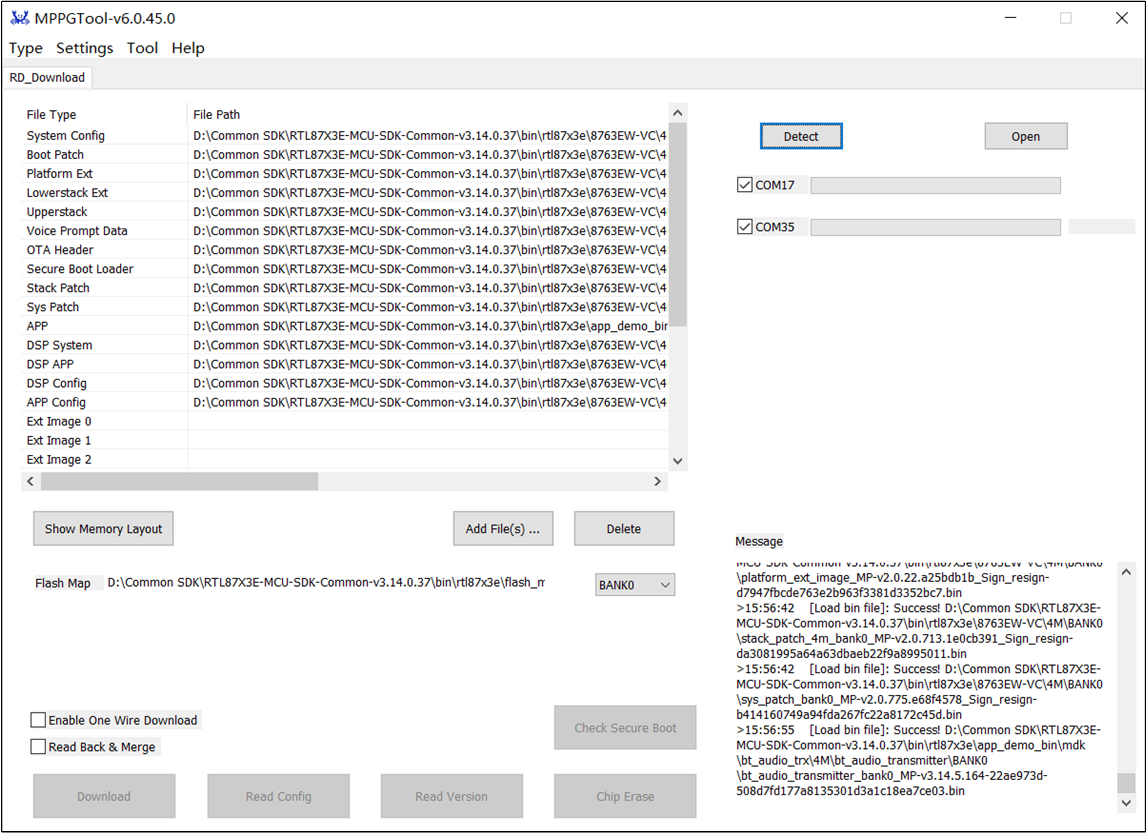
All Download Bin
If the IC type supports GUI functionality, it will also require downloading a resource bin named
userdata.bin, which includes font and image resources.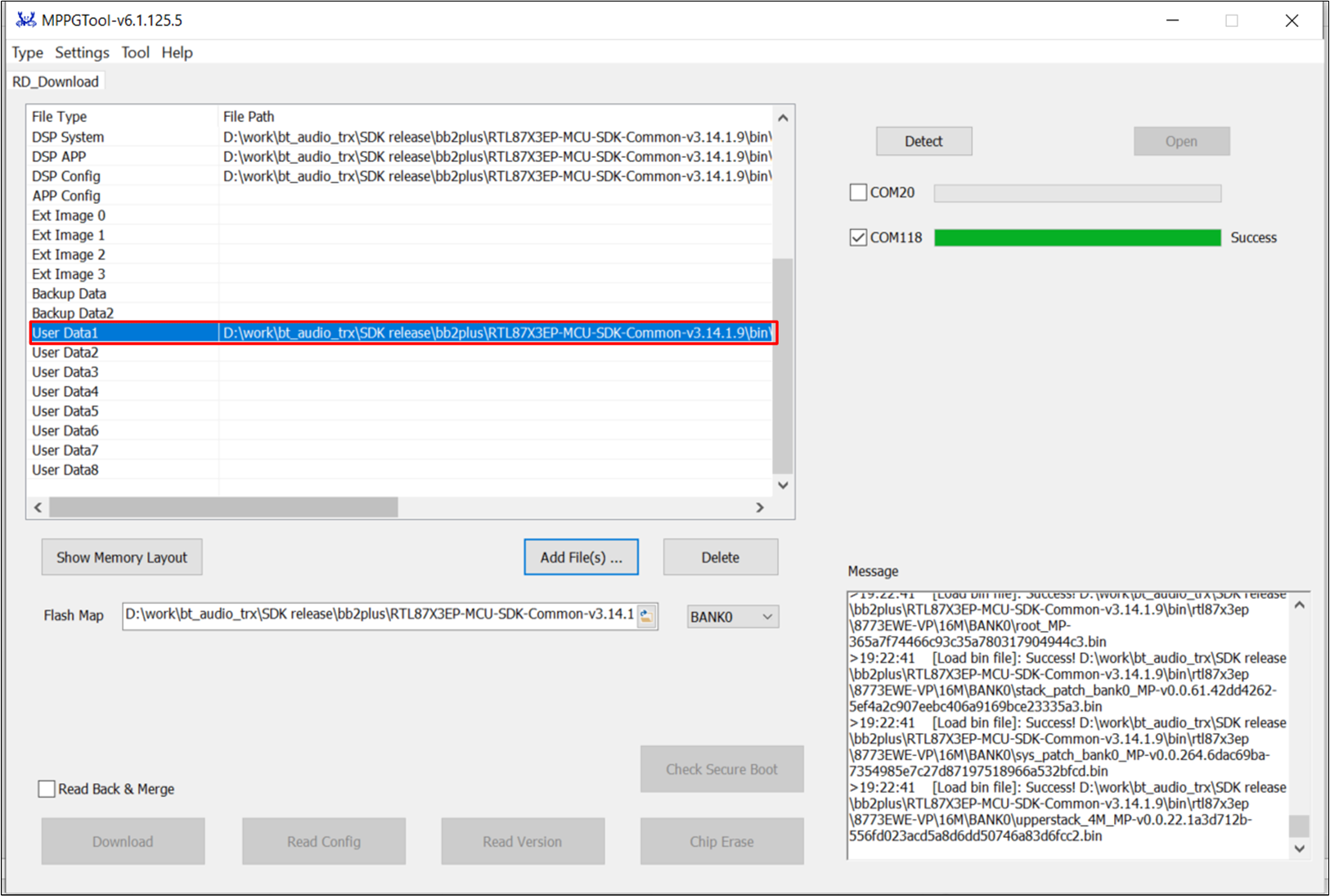
Userdata Bin
Userdata bin which prefix starts with
rootis in the directorybin\rtl87x3e\flash_16M_dualbank\bank0.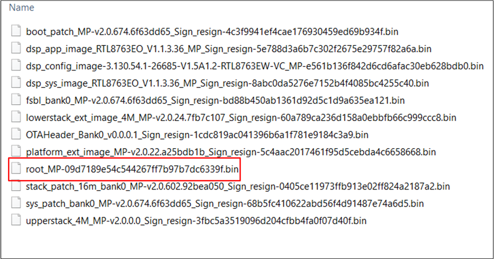
Userdata Location
Press the reset on the EVB board.
Experimental Verification
After programming the application bin to the EVB board, it can be tested with a Bluetooth headset.
Testing with Bluetooth Headset
Prepare a development board named DUT and a Bluetooth headset, and use Debug Analyzer to get the logs.
Building and Downloading the application and downloading images into DUT.
Put the headset into pairing mode.
Press the reset on the DUT, and if boot is successful, the LCD will show the screen below:
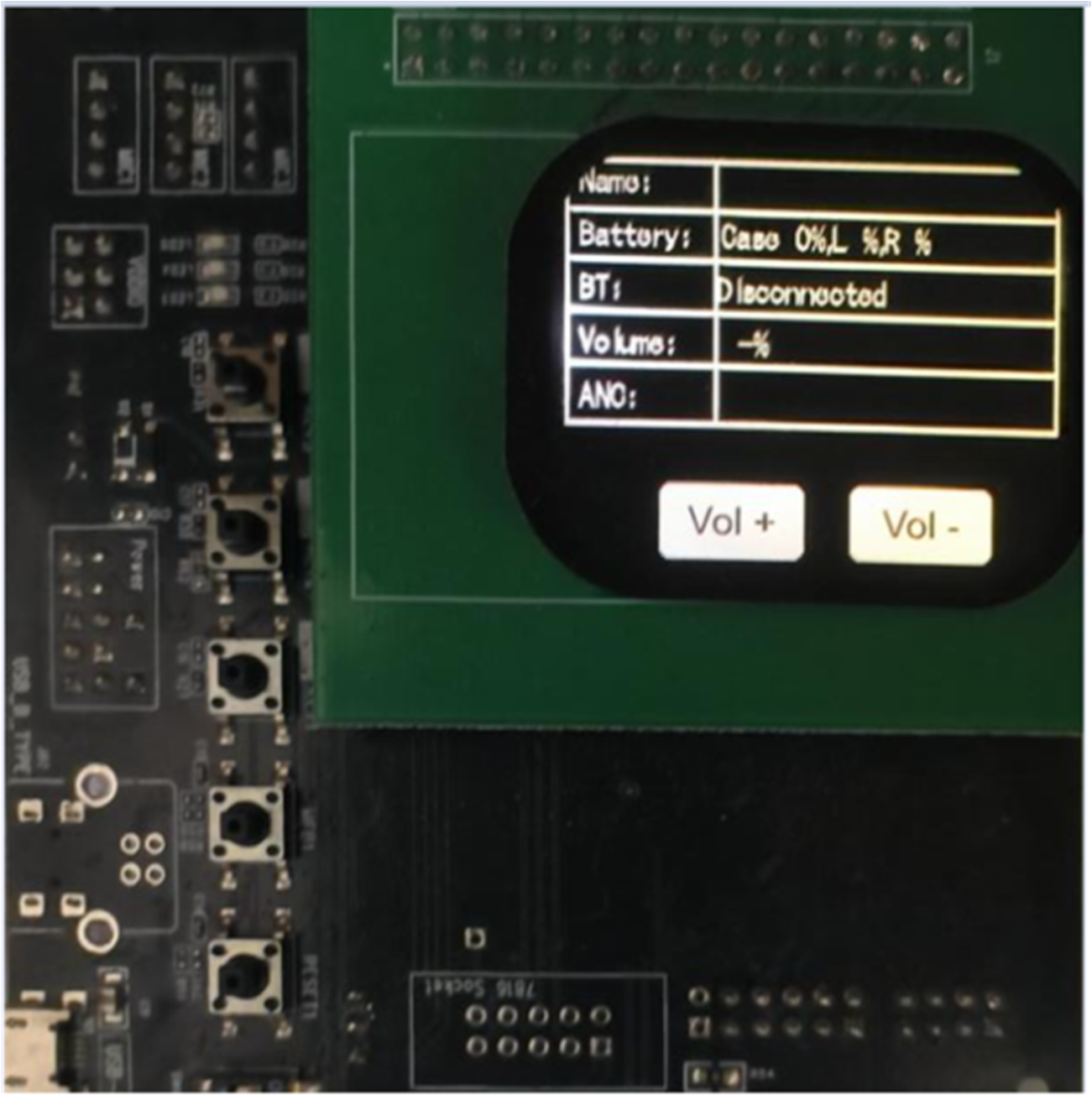
Normal Display
Using the ACI Host CLI Tool to send commands to connect to the headset:
Open
opcode.jsoninsdk\tool\AciHostCLIfilepath.Find le connect sample CMD and change the address to the headset address.
Choose the right COM in the
config.ymland launch theAciHostCLI.exe.Execute mmi poweron CMD.
Execute le connect sample CMD.
Control the DUT to speak through the DUT’s microphone. Make sure that the sound can be heard from the headset. Please refer to MIC Source Play for details.
When the headset is connected to the phone again and music is playing on the phone, the user can touch the volume up or volume down button. It is expected that the volume of music played on the phone will change accordingly.
The software design of the charge case and the communication design between the charge case and the headphones can be referenced in Software Design Introduction.
Software Design Introduction
The following topics are included:
Source Code Directory.
Flash Layout.
Software Architecture.
Task and Priority.
Main Functions.
GUI.
Communication between Charging Case and Headset.
Before reading the content of this document, it is highly recommended to first read the following documents:
The charge case demo is developed based on bt_audio_trx, and all the functions are the same. It only adapts some features for the charge case by turning certain functions on or off using macro switches and adds a display screen to show some information. Therefore, if user wants to understand the charge case demo, it is recommended to first read the relevant introduction of bt_audio_trx.
Source Code Directory
Project directory:
sdk\board\evb\bt_audio_trx.Source code directory:
sdk\src\sample\bt_audio_trx.
Source files in the sample project are currently categorized into several groups as below:
└── Project: bt_audio_trx
├── include
└── cmsis includes startup code
├── startup_rtl87x3e.s
└── system_rtl8x.c
├── lib includes all binary symbol files that user application is built on
└── le includes LE client or services used by the application
├── ancs.c
├── ota_service.c
├── ams.c
:
└── dis_gatt_client.c
└── app includes the application implementation
├── app_task.c
├── app_cfg.c
├── main.c
:
├── app_mmi.c
└── app_key_cfg.c
└── bredr includes bredr profile used by the application
├── app_a2dp.c
├── app_hfp.c
:
└── app_spp.c
:
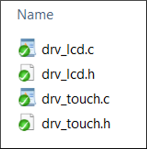
├── module includes lcd and touch driver used by the application
└── gui includes UI demo used by the application
Flash Layout
Application default flash layout header file:
sdk\bin\rtl87x3e\flash_map_config\16M\flash_16M\flash_map.h.Application default flash layout configuration file:
sdk\bin\rtl87x3e\flash_map_config\16M\flash_16M\flash_map.ini.
Software Architecture
The software architecture of the system is shown below:
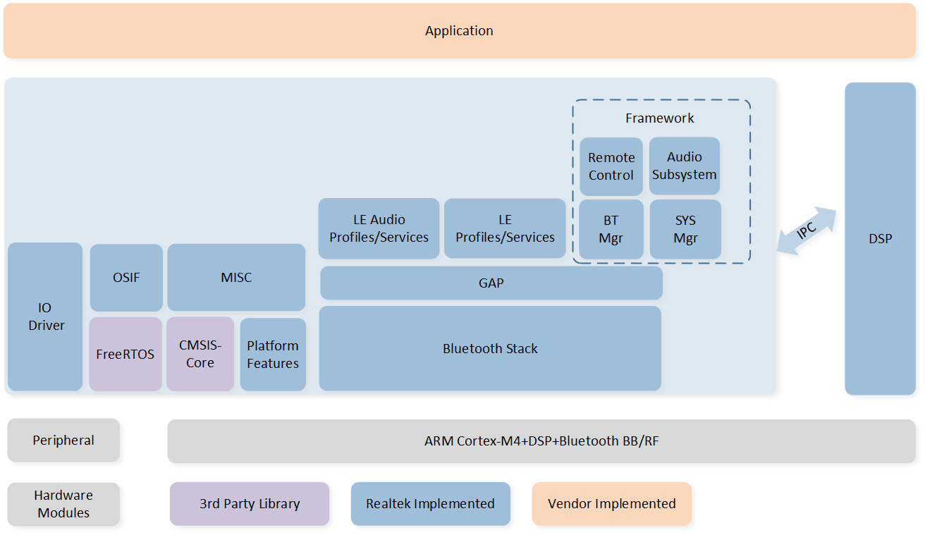
GUI Software Architecture
The system architecture consists of several key components:
GAP: It is the abstraction layer that allows the user application to communicate with the dual-mode stack.
Framework Library: It includes the latest Bluetooth classic protocols/profiles and Realtek proprietary protocols, such as A2DP/HFP, etc. Detailed information can be found in BR/EDR Profiles.
Audio Subsystem: It provides audio-related functions. Please refer to Audio Subsystem for more details.
Leaudio Library: It includes LE audio profiles.
DSP SDK: It is an abstraction of DSP. DSP communicates with MCU via IPC. Please see the DSP SDK for details on the DSP modules.
IO Drivers: These drivers provide API for the user application to interface with Bluetooth Audio SoC on-board peripherals without directly accessing registers.
OSIF: It is an abstraction of real-time OS interfaces for the user application.
GUI: It is an abstraction of GUI interfaces for the user application. If users want to learn more about GUI-related information, please refer to RTKIOT GUI on RealMCU.
Block Diagram
The following figure shows an overview of the modules currently included in the charging case application:
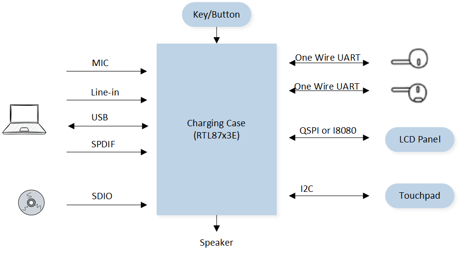
Block Diagram
The charging case provides MIC/Line-in/USB/SDIO/SPDIF interfaces to receive audio data:
MIC interface: The microphone interface on the charging case can be used to receive external audio signals. Through this interface, the charging case can capture sounds from external devices.
Line-in interface: The line input interface on the charging case can be used to receive audio signals from other audio devices. This interface allows the charging case to receive audio signals from devices like MP3 players or computers.
USB interface: The charging case has a USB interface that can be connected to a computer or other USB devices. Through this interface, the charging case can receive audio signals from USB devices.
SDIO interface: The SDIO interface on the charging case can receive audio data from an card. The SD card can serve as storage media, and the charging case can read audio files from it for playback.
SPDIF interface: The SPDIF (Sony/Philips Digital Interface) interface is a digital audio interface that allows the charging case to receive digital audio signals from other devices.
The charging case also utilizes a key module to handle user button presses. Through the key module, users can perform different operations on the charging case, such as adjusting volume or changing tracks.
Communication with the headset is done through one wire UART. The charging case interacts with the headset through this UART interface, allowing them to exchange data without the need for complex hardware connections.
The charging case can drive the LCD panel using either the QSPI or I8080 interface. These interfaces provide connectivity and control over the LCD panel, enabling the charging case to display relevant information or interfaces.
To control the touchpad, the charging case uses the I2C interface. Through the I2C interface, the charging case can communicate with the touchpad to detect and respond to touch interactions.
Link Topology
The following figure shows an overview of the link topology currently included in the charging case application:
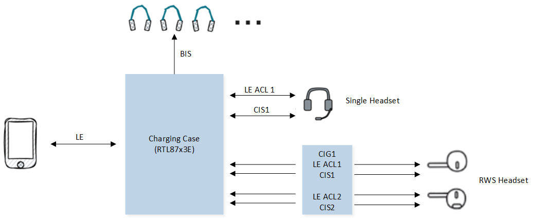
Link Topology
There is one LE ACL between the mobile phone and the charging case. There may be either one or two LE ACLs between the charging case and the headset. The mobile phone can transmit audio data to the charging case through BIS or CIS.
Audio Stream
The following figure shows an overview of the audio stream currently included in the charging case application:
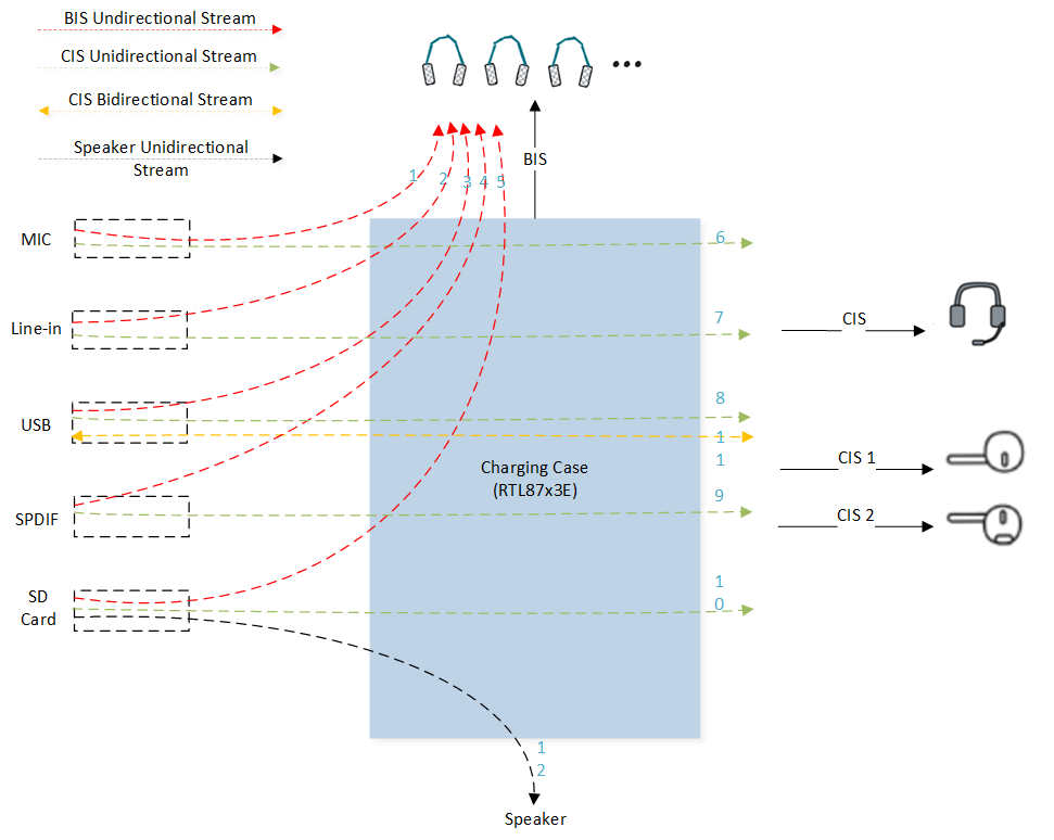
Audio Streaming
There are four types of audio streams: BIS unidirectional audio, CIS unidirectional audio, CIS bidirectional audio, and Speaker unidirectional audio.
Audio Stream Type |
Description |
|---|---|
BIS Unidirectional Audio |
MIC in + BIS out (1)nLine-in + BIS out (2)nUAC in + BIS out (3)nSPDIF in + BIS out (4)nSD Card in + BIS out (5) |
CIS Unidirectional Audio |
MIC in + CIS out (6)nLine-in + CIS out (7)nUAC in + CIS out (8)nSPDIF in + CIS out (9)nSD Card in + CIS out (10) |
CIS Bidirectional Audio |
UAC in/out + CIS out/in (11) |
Speaker Unidirectional Audio |
SD Card in + Speaker out (12) |
Note
Audio data from MIC/Line-in/USB/SDIO/SPDIF interfaces can also be transmitted via A2DP/HFP, which is not depicted in the image.
Due to the limitations of DSP RAM, the speaker function and CIS function cannot be supported simultaneously.
The data flow descriptions from 1 to 12 in the table can correspond to 1 to 12 in the scenario diagram above.
Task and Priority
As shown below, eight tasks have been created for the user application:
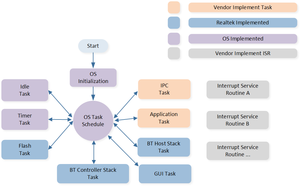
Task
The description of each task and its priority is shown in the table below:
Task |
Description |
Priority |
|---|---|---|
Timer |
Implement the software timer required by FreeRTOS. |
6 |
Bluetooth Controller |
Implement Bluetooth stack protocols below HCI. |
6 |
Bluetooth Host |
Implement Bluetooth stack protocols above HCI. |
3 |
Application |
Handle user application requirements and interact with the stack. |
2 |
Flash |
Handle asynchronous flash requests. |
1 |
Idle |
Run background tasks, including DLPS. |
0 |
IPC |
Process communications between MCU and DSP2. |
2 |
GUI |
Handle the generation of images, the transmission of screen data, and the parsing of touch gestures. |
1 |
Note
Multiple application tasks can be created, and memory resources will be allocated accordingly.
The idle tasks and the timer task are provided by FreeRTOS.
Tasks have been configured to be preemptive based on their priority using the
SysTickinterrupt.Interrupt Service Routines (ISR) have been implemented by the vendor.
The IPC task only exists in RTL87x3D.
Main Functions
This chapter lists the main functions supported in the charging case demo. The main functions are listed as follows:
Supported Chip-sets.
One Wire UART.
Line-in Audio + CIS.
Line-in Audio + BIS.
UAC + CIS.
UAC + BIS.
USB Mass Storage.
Local MP3 + BIS/CIS.
Local MP3 + Local Playback.
ACI Control over LE.
Auracast Assistant.
Find My.
Device Firmware Update.
Note
By default, some features are not enabled. You can check
app_flags.hto see which features are enabled by default. You can also enable or disable specific features based on the requirements of your actual product.
Supported Chip-sets
The chip-sets that are designed to support the charging case application are listed in the table below:
Features |
RTL8763EWE/VP |
RTL8763EW-VC |
RTL8773DO |
|---|---|---|---|
LE |
Y |
Y |
Y |
Bluetooth Legacy |
Y |
Y |
Y |
LE Audio |
N |
Y |
Y |
N |
Y |
Y |
|
Auracast TX |
N |
Y |
Y |
Auracast Assistant |
N |
Y |
Y |
Find My |
Y |
Y |
Y |
I8080 |
Y |
Y |
N |
SPDIF |
N |
N |
Y |
UAC |
N |
Y |
Y |
Y |
Y |
Y |
|
MIC |
Y |
Y |
Y |
GUI |
Y |
Y |
Y |
One Wire UART
Please refer to One Wire UART for details.
Line-in Audio + CIS
Please refer to Line-in Source Play (CIS Output) for details.
Line-in Audio + BIS
Please refer to Line-in Source Play (BIS Output) for details.
UAC + CIS
This topology has two modes, for more information, please refer to the detailed description of each mode below.
Media Mode (CIS Output)
Please refer to USB Source Play (CIS Output) for details.
Conversation Mode (CIS Input and Output)
Please refer to USB Source Play (CIS Input and Output) for details.
UAC + BIS
Please refer to USB Source Play (BIS Output) for details.
USB Mass Storage
Please refer to USB Mass Storage for details.
Local MP3 + BIS/CIS
Please refer to SD Card Source Play (BIS/CIS Output) for details.
Local MP3 + Local Playback
Please refer to SD Card Source Play for details.
ACI Control over LE
The LE (Low Energy) control of the charging case is divided into audio control and voice control:
Audio Control includes functionalities like volume up, volume down, play, pause, forward, backward, etc.
Voice Control includes actions such as MIC mute, MIC unmute, answer call, end call, reject call, etc.
The charging case sends control commands to the headset through the following interface:
void app_le_transfer_control_cmd_handle(uint8_t app_idx, uint8_t cmd_path, uint8_t *cmd_ptr,
                                        uint16_t cmd_len, uint8_t *ack_pkt)
{
    uint16_t cmd_id = (uint16_t)(cmd_ptr[2] | (cmd_ptr[3] << 8));

    APP_PRINT_TRACE3("app_le_transfer_control_cmd_handle: cmd_id 0x%04x, cmd_len 0x%04x, cmd_path %u",
                     cmd_id, cmd_len, cmd_path);

    switch (cmd_id)
    {
    case CMD_SET_VOLUME:
        {
            uint8_t volume_level = cmd_ptr[4];
            uint8_t max_volume = 0x0F;
            uint8_t min_volume = 0;
            if (volume_level < min_volume || volume_level > max_volume)
            {
                ack_pkt[2] = CMD_SET_STATUS_PARAMETER_ERROR;
            }
            else
            {
                app_le_transfer_start(cmd_len - 2, &cmd_ptr[2]);
            }

            app_cmd_set_event_ack(cmd_path, app_idx, ack_pkt);
        }
        break;

    case CMD_MMI:
    case CMD_SET_VP_VOLUME:
    case CMD_AUDIO_EQ_INDEX_SET:
    case CMD_SET_KEY_MMI_MAP:
    case CMD_LISTENING_MODE_CYCLE_SET:
    case CMD_LISTENING_STATE_SET:
        {
            app_le_transfer_start(cmd_len - 2, &cmd_ptr[2]);

            app_cmd_set_event_ack(cmd_path, app_idx, ack_pkt);
        }
        break;

    default:
        break;
    }
}
Auracast Assistant
Auracast Assistant is a Bluetooth device capable of assisting an Auracast receiver in receiving an Auracast broadcast. Auracast assistants scan for Auracast advertisements and provide a user interface (UI) to enable users to select an Auracast broadcast to join, similar to the UI commonly used to connect to Wi-Fi networks in public spaces.
How it works:
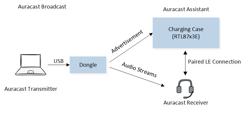
Auracast Work
When wanting to verify Auracast Assistant, please do it step by step as follows:
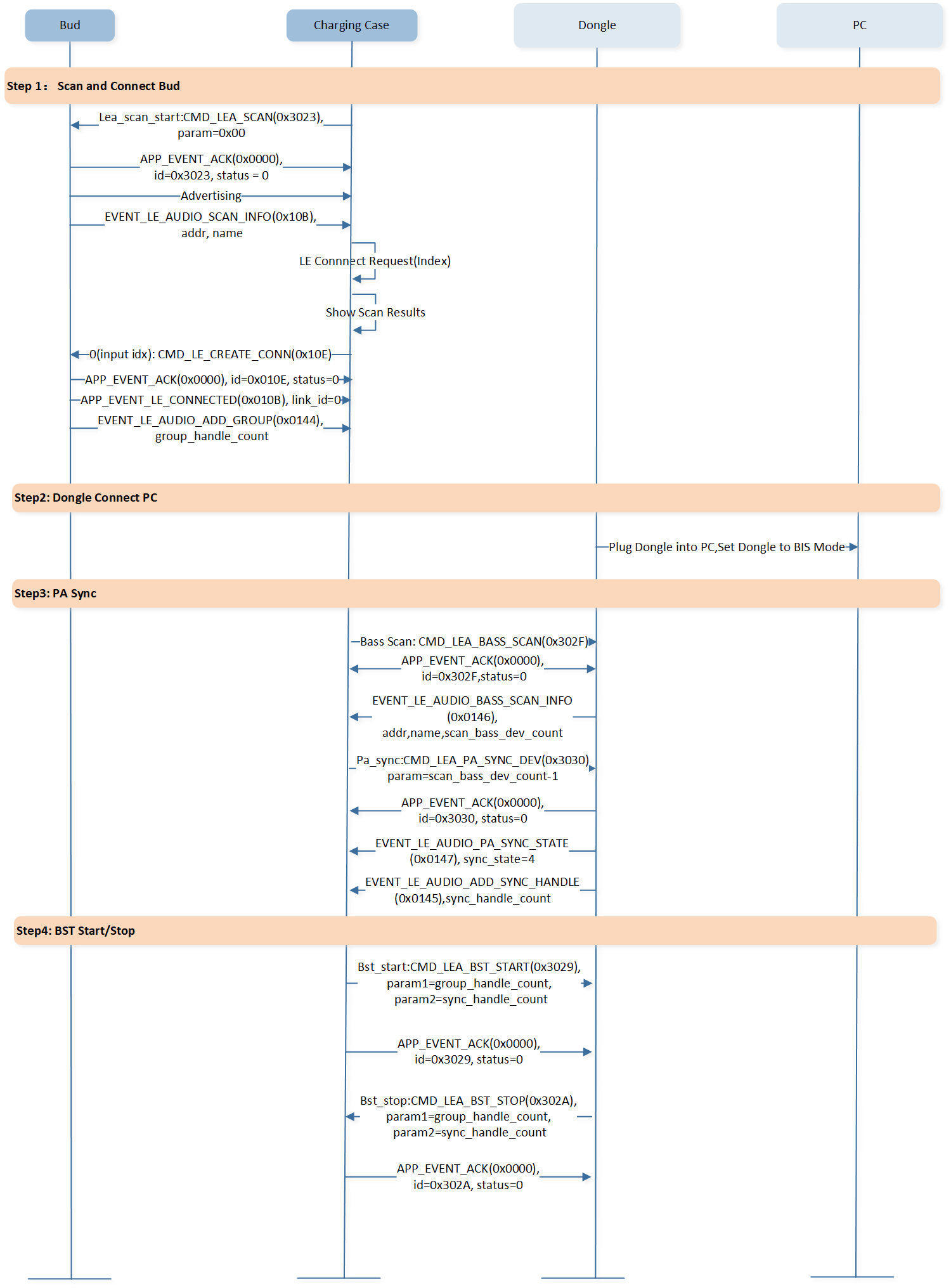
Auracast Test
Find My
Please refer to Find My for details.
Device Firmware Update
Supports firmware upgrade in two ways: OTA and USB DFU.
OTA
Over the air update, please refer to OTA for details.
USB DFU
Update images over USB, please refer to CFU for details.
GUI
This chapter mainly introduces the framework of GUI in the APP layer, the initialization process, the interaction between GUI and APP tasks, as well as the currently supported demos. To learn more about the GUI engine, please refer to RTKIOT GUI on RealMCU.
To enable the GUI functionality, set F_APP_GUI_SUPPORT to 1. In GUI applications, PSRAM can be used to store image data, including background images, icons, buttons, and more. With its fast read-write capability, PSRAM enables quick image display and refresh, providing a smooth user experience.
Note
Using PSRAM can effectively reduce tearing.
#if (CONFIG_REALTEK_TARGET_RTL8763EW_VC || CONFIG_REALTEK_TARGET_RTL8763EWE_VP || CONFIG_REALTEK_TARGET_RTL8763EWE || TARGET_RTL8773DO || (TARGET_RTL87X3EP && !TARGET_4M))
#undef F_APP_GUI_SUPPORT
#define F_APP_GUI_SUPPORT                       1
#undef ENABLE_PSRAM_FOR_LCD
#define ENABLE_PSRAM_FOR_LCD                    0
//#define  ENABLE_RTK_GUI_SCRIPT_AS_A_APP
#endif
GUI Code Framework
APP GUI code path is sdk\src\sample\bt_audio_trx\panel:
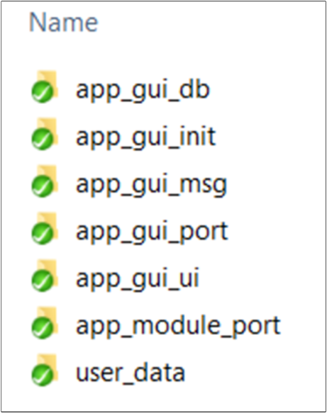
GUI Framework
There are seven folders in this path:
app_gui_db: Code for saving data from APP task.app_gui_init: Code for GUI init process.app_gui_msg: Code for handling msgs from GUI task.app_gui_port: Code for adapting the GUI engine module.app_module_port: Code for adapting driver module.app_gui_ui: UI demo.userdata: Code for the address of font and image resources.
GUI Init Process
Please refer to app_panel_init.c:
app_io_resource_request_init();  // dma resource init
app_flash_resource_init();       // flash resource init
app_psram_resource_init();       // psram resource init
app_components_init();           // lcd and touch resource init
extern gui_app_t *get_app_panel(void);
#ifdef ENABLE_RTK_GUI
    gui_server_init();                // gui engine init
    #ifdef ENABLE_RTK_GUI_SCRIPT_AS_A_APP
    #else
        gui_app_install(get_app_panel(), get_app_panel()->ui_design, NULL);   // load panel info
        gui_app_startup(get_app_panel());                                     // start GUI task
    #endif
#endif
GUI Adaptation File
The GUI engine module is an independent module that can run on multiple platforms. Before running, the APP should set platform API for the GUI engine module, including display\filesystem\os\touch:
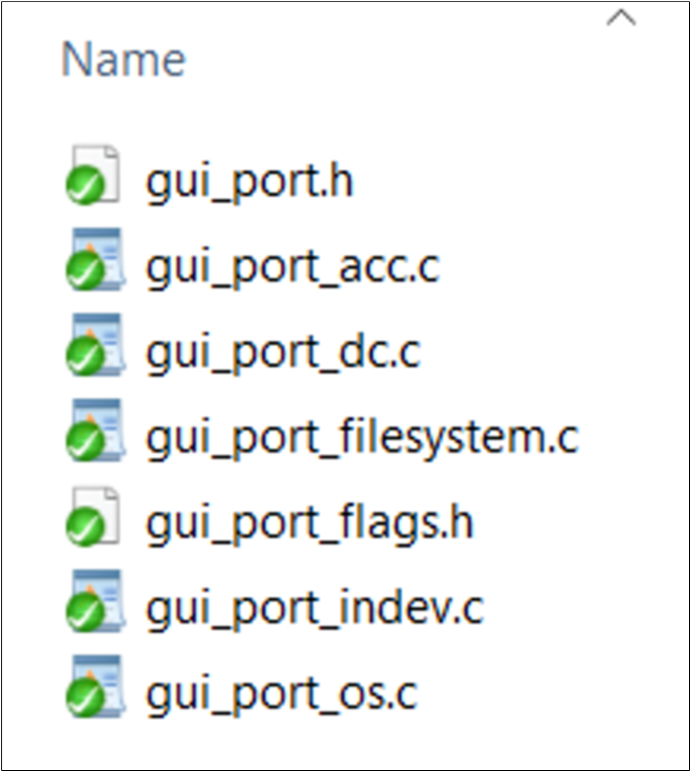
GUI Adaptation File
Driver Adaptation File
The driver provides various interfaces, which are re-encapsulated with APP layer interfaces to facilitate future management:
Driver Adaptation File
GUI Database
APP task could send data to GUI task directly, and GUI task has a database to save all data from APP task before mapping to display effect, mainly divided into three files to store data:
app_panel_device_db.c.typedef struct app_gui_device_data_t { char device_name[APP_GUI_DEVICE_NAME_MAX_LENGTH]; uint8_t battery_level; uint8_t res[3]; } T_APP_GUI_DEVICE_DATA; static T_APP_GUI_DEVICE_DATA app_gui_device_info;
Device data is about status or configuration of the current device, like device name or battery power.
app_panel_bredr_db.c.typedef struct app_gui_bredr_link_data_t { bool active; uint8_t bd_addr[6]; } T_APP_GUI_BREDR_LINK_DATA; typedef struct app_gui_bredr_data_t { T_APP_GUI_BREDR_LINK_DATA gui_bredr_link_data[MAX_BR_LINK_NUM]; } T_APP_GUI_BREDR_DATA; T_APP_GUI_BREDR_DATA app_gui_bredr_data;
BR/EDR data refers to the information about the remote device that is linked with the current device by BR/EDR protocol.
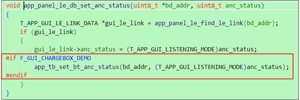
app_panel_le_db.c.typedef struct app_gui_le_link_data_t { bool active; uint8_t bd_addr[6]; T_REMOTE_SESSION_ROLE bud_role; T_APP_GUI_LE_BUD_SIDE bud_side; uint8_t battery_level; uint8_t volume; bool anc_status; } T_APP_GUI_LE_LINK_DATA; typedef struct app_gui_le_data_t { T_APP_GUI_LE_LINK_DATA gui_le_link_data[MAX_BLE_LINK_NUM]; } T_APP_GUI_LE_DATA; static T_APP_GUI_LE_DATA app_gui_le_data;
LE data is about information of the remote device linked with current device by LE protocol.
The database enables the APP task to operate without having to monitor the status of the GUI task. The decision to continuously refresh the GUI widget or actively query data using the GUI widget entirely depends on the user’s design needs:
Setting data to GUI widget:
Set Data Directly
Querying data by GUI widget actively:
snprintf(battery_level, sizeof(battery_level), "Battery:  Case %d%%,L %d%%,R %d%%",
         app_panel_device_db_get_bettery_level(),
         app_panel_le_db_get_left_device_battery(),
         app_panel_le_db_get_right_device_battery());
gui_text_content_set(text_battery_level, battery_level, strlen(battery_level));
GUI Message Handle
The GUI task could send messages to the APP task to trigger some actions, like scanning, connecting, or powering off. The GUI sending message API is as follows:
bool app_panel_msg_send_to_app(T_APP_GUI_MSG *data)
{
    if (os_msg_send(gui_msg_queue_handle, data, 0) != true)
    {
        APP_PRINT_ERROR0("app_panel_msg_send_to_app: send msg to gui msg queue failed");
        return false;
    }

    uint8_t event = (uint8_t)(EVENT_IO_TO_APP << 4);
    if (os_msg_send(audio_evt_queue_handle, &event, 0) != true)
    {
        APP_PRINT_ERROR0("app_panel_msg_send_to_app: send msg to gui event queue failed");
        return false;
    }
    return true;
}
There are two queues that record events and data respectively in the APP task:
void *gui_msg_queue_handle = NULL;
void *gui_evt_queue_handle = NULL;
When the APP task receives a GUI event, the APP task reads GUI data from the GUI data queue. The general message processing entry is app_panel_msg_handle() in app_panel_msg.c:
void app_panel_msg_handle(uint8_t event)
{
    T_APP_GUI_MSG gui_msg;
    if (os_msg_recv(gui_msg_queue_handle, &gui_msg, 0) == true)
    {
        switch (gui_msg.type)
        {
        case EVENT_GUI_TO_DEVICE:
            app_panel_device_msg_handle(&gui_msg);
            break;
        case EVENT_GUI_TO_BREDR:
            app_panel_bredr_msg_handle(&gui_msg);
            break;
        case EVENT_GUI_TO_BLE:
            app_panel_le_msg_handle(&gui_msg);
            break;
        default:
            break;
        }
    }
}
Then handling corresponding GUI data according to category which is device data, BR/EDR link data, or LE link data, this part of the process logic is in three files:
app_panel_device_msg.c.void app_panel_device_msg_handle(T_APP_GUI_MSG *data) { switch (data->subtype) { default: break; } }
app_panel_bredr_msg.c.void app_panel_bredr_msg_handle(T_APP_GUI_MSG *data) { switch (data->subtype) { default: break; } }
app_panel_le_msg.c.void app_panel_le_msg_handle(T_APP_GUI_MSG *data) { switch (data->subtype) { case GUI_LE_SUBEVENT_ADJUST_VOLUME: if (data->u.param == GUI_ADJUST_VOLUME_UP) { #if TRANSMIT_CLIENT_SUPPORT app_le_transfer_volume_control(LE_TRANSFER_CONTROL_VOLUME_UP); #endif } else { #if TRANSMIT_CLIENT_SUPPORT app_le_transfer_volume_control(LE_TRANSFER_CONTROL_VOLUME_DOWN); #endif } break; default: break; } }
For category explanation, please see the previous chapter.
UI Design
The SDK provides several UI demos for users. Currently, it includes three UI demos:
Speed dashboard: Demonstrates the usage of image and text widgets.
SD card list: Showcases the usage of the pagelist widget.
Chargebox: Offers a simple demo related to a chargebox product.
The UI design entry API is located in app_panel.c as follows:
static void app_panel_ui_design(gui_app_t *app)
{
#if F_GUI_SIMPLE_SPEED_DEMO
    app_simple_speed_ui_design(app);
#elif F_GUI_SDCARD_LIST_DEMO
    app_sdcard_list_ui_design(app);
#elif F_GUI_CHARGEBOX_DEMO
    app_chargebox_ui_design(app);
#endif
}
Users can design their own UI effects in independent C files and add the entry API to app_panel_ui_design().
For specific GUI widget usage, please refer to RTKIOT GUI on RealMCU.
Resource Address
Image and font resources are packaged by a Python script, and this process generates a header file named resource.h. The addresses provided in this file are used by the UI design code, so it is crucial to maintain the latest version of resource.h in the user_data folder.
Communication between Charging Case and Headset
Commands can be sent, and status updates can be received between the charging case and headset using CMDs and Events. For example, the headset can control the charging case to open or close the lid, or the charging case can control the headset to adjust the volume. The specific formats of CMDs and Events can be found in the sections below.
Protocol
Please refer to the section Application Controller Interface Commands and Events for details.
Open Case
The AD2B_CMD_OPEN_CASE command is used to open the case and send the command to the headset through a one-wire UART. The headset will power on after receiving the open case command:
void app_charging_case_send_cmd(uint16_t cmd_id)
{
    uint8_t temp_buff[3] = {0};
    bool cmd_flag = true;
    APP_PRINT_INFO1("app_charging_case_send_cmd: cmd_id %d", cmd_id);

    switch (cmd_id)
    {
    case AD2B_CMD_OPEN_CASE:
        {
            temp_buff[0] = AD2B_CMD_OPEN_CASE;
        }
        break;
...
    default:
        cmd_flag = false;
        break;
    }

    if (cmd_flag)
    {
        app_report_charging_case_cmd(CMD_PATH_UART, CMD_ADP_CMD_CONTROL, 0, temp_buff, sizeof(temp_buff));
        app_report_charging_case_cmd(CMD_PATH_UART, CMD_ADP_CMD_CONTROL, 2, temp_buff, sizeof(temp_buff));
    }
}
Close Case
The AD2B_CMD_CLOSE_CASE command is used to close the case. The headset will power off upon receiving the command:
void app_charging_case_send_cmd(uint16_t cmd_id)
{
    uint8_t temp_buff[3] = {0};
    bool cmd_flag = true;
    APP_PRINT_INFO1("app_charging_case_send_cmd: cmd_id %d", cmd_id);

    switch (cmd_id)
    {
    case AD2B_CMD_CLOSE_CASE:
        {
            temp_buff[0] = AD2B_CMD_CLOSE_CASE;
        }
        break;
...
    default:
        cmd_flag = false;
        break;
    }

    if (cmd_flag)
    {
        app_report_charging_case_cmd(CMD_PATH_UART, CMD_ADP_CMD_CONTROL, 0, temp_buff, sizeof(temp_buff));
        app_report_charging_case_cmd(CMD_PATH_UART, CMD_ADP_CMD_CONTROL, 2, temp_buff, sizeof(temp_buff));
    }
}
Auto Pairing
After receiving the in case command, the charging case determines whether it is paired with the headset. If not, it completes the pairing process by generating bond information.
Note
The charging case will only retain the address of one earphone as the pairing earphone address.
Because the battery case does not distinguish between primary and secondary earbuds, if two new devices are placed into the case one after the other, the address of the last device will be set as the earbud address. The earbud will ensure that the address of the last device placed into the case is the primary earbud address.
After automatic pairing is completed, the charge case will actively establish an LE connection with the paired earphones. If the connection is later disconnected, the charge case will also initiate reconnection, except in one scenario: when the earphones set the charge case to enter OTA mode, at which point the battery case will not reconnect.
The flowchart is as follows:
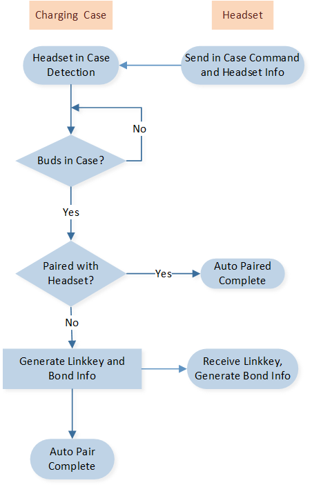
Auto Pairing Flowchart
The code is as follows:
void app_charging_case_cmd_handle(uint8_t app_idx, uint8_t cmd_path, uint8_t *cmd_ptr,
                                  uint16_t cmd_len, uint8_t *ack_pkt)
{
    uint16_t cmd_id = (uint16_t)(cmd_ptr[0] | (cmd_ptr[1] << 8));

    switch (cmd_id)
    {
    case CMD_CHARGER_CASE_BUD_ALL_IN_CASE:
        {
            T_LE_BOND_ENTRY *p_entry = NULL;
            uint8_t local_bd_addr[6] = {0};
            uint8_t temp_buff[24] = {0};
            uint8_t p_key_len;
            uint8_t p_key[16] = {0};

            memcpy(remote_bd_addr, &cmd_ptr[2], 6);
            T_GAP_REMOTE_ADDR_TYPE remote_addr_type = (T_GAP_REMOTE_ADDR_TYPE)cmd_ptr[8];
            memcpy(local_bd_addr, app_cfg_nv.bud_local_addr, 6);
            uint8_t local_bd_type = LE_BOND_LOCAL_ADDRESS_ANY;

            p_entry = bt_le_find_key_entry(remote_bd_addr, remote_addr_type, local_bd_addr, local_bd_type);

            if (p_entry)
            {
                temp_buff[0] = CHARGING_CASE_BOND_STATE_BONED;
                temp_buff[1] = LE_BOND_LOCAL_ADDRESS_ANY;
                memcpy(&temp_buff[2], local_bd_addr, 6);
                if (bt_le_get_dev_ltk(p_entry, false, &p_key_len, p_key))
                {
                    temp_buff[1] = LE_BOND_LOCAL_ADDRESS_ANY;
                    memcpy(&temp_buff[8], p_key, p_key_len);
                }
                else
                {
                    ack_pkt[2] = CMD_SET_STATUS_PROCESS_FAIL;
                }
            }
            else
            {
                temp_buff[0] = CHARGING_CASE_BOND_STATE_NONE;
                temp_buff[1] = LE_BOND_LOCAL_ADDRESS_ANY;
                memcpy(&temp_buff[2], local_bd_addr, 6);
                app_charging_case_link_key_random_gen(p_key);

                if (app_charging_case_set_fast_pair_info(p_key))
                {
                    memcpy(&temp_buff[8], p_key, p_key_len);
                }
                else
                {
                    ack_pkt[2] = CMD_SET_STATUS_PROCESS_FAIL;
                }
            }

            app_report_charging_case_cmd(CMD_PATH_UART, CMD_CHARGER_CASE_LE_LINK_INFO, 0, temp_buff,
                                         sizeof(temp_buff));
            app_cmd_set_event_ack(cmd_path, app_idx, ack_pkt);
        }
        break;

    default:
        break;
    }
}
Troubleshooting
This section introduces some frequently asked questions.
How to Extend the Commands between the Charging Case and the Headset?
APP can use the function app_charging_case_send_cmd() to extend one wire UART commands. The charging case uses the function app_report_charging_case_cmd() to send commands to the headset:
void app_charging_case_send_cmd(uint16_t cmd_id)
{
    uint8_t temp_buff[3] = {0};
    bool cmd_flag = true;
    APP_PRINT_INFO1("app_charging_case_send_cmd: cmd_id %d", cmd_id);

    switch (cmd_id)
    {
    case AD2B_CMD_FACTORY_RESET:
        {
            temp_buff[0] = AD2B_CMD_FACTORY_RESET;
            temp_buff[1] = 0x55;
        }
        break;
    ...
    default:
        cmd_flag = false;
        break;
    }

    if (cmd_flag)
    {
        app_report_charging_case_cmd(CMD_PATH_UART, CMD_ADP_CMD_CONTROL, 0, temp_buff, sizeof(temp_buff));
        app_report_charging_case_cmd(CMD_PATH_UART, CMD_ADP_CMD_CONTROL, 2, temp_buff, sizeof(temp_buff));
    }
}
APP can use the function app_le_transfer_control_cmd_handle() to extend LE commands. The charging case uses the function app_le_transfer_start() to send commands to the headset:
void app_le_transfer_control_cmd_handle(uint8_t app_idx, uint8_t cmd_path, uint8_t *cmd_ptr,
                                        uint16_t cmd_len, uint8_t *ack_pkt)
{
    uint16_t cmd_id = (uint16_t)(cmd_ptr[2] | (cmd_ptr[3] << 8));

    APP_PRINT_TRACE3("app_le_transfer_control_cmd_handle: cmd_id 0x%04x, cmd_len 0x%04x, cmd_path %u",
                     cmd_id, cmd_len, cmd_path);

    switch (cmd_id)
    {
    case CMD_SET_VOLUME:
        {
            uint8_t volume_level = cmd_ptr[4];
            uint8_t max_volume = 0x0F;
            uint8_t min_volume = 0;
            if (volume_level < min_volume || volume_level > max_volume)
            {
                ack_pkt[2] = CMD_SET_STATUS_PARAMETER_ERROR;
            }
            else
            {
                app_le_transfer_start(cmd_len - 2, &cmd_ptr[2]);
            }

            app_cmd_set_event_ack(cmd_path, app_idx, ack_pkt);
        }
        break;

    case CMD_MMI:
    case CMD_SET_VP_VOLUME:
    case CMD_AUDIO_EQ_INDEX_SET:
    case CMD_SET_KEY_MMI_MAP:
    case CMD_LISTENING_MODE_CYCLE_SET:
    case CMD_LISTENING_STATE_SET:
        {
            app_le_transfer_start(cmd_len - 2, &cmd_ptr[2]);

            app_cmd_set_event_ack(cmd_path, app_idx, ack_pkt);
        }
        break;

    default:
        break;
    }
}