OTA
OTA refers to the wireless delivery of software updates to devices. The SDK supports OTA via Bluetooth and provides two Bluetooth transport methods for Android and iOS.
To achieve OTA functionality, it is generally necessary to set up an OTA firmware upgrade system as shown in the figure below. This application firmware upgrade system consists of three parts.
Cloud Server: Storing upgrade files.
Mobile Device: The OTA controller role during the OTA process.
SoC to Be Upgraded: The OTA target role during the OTA process.
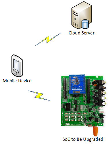
OTA Firmware Upgrade System
This document provides detailed information related to OTA. The following topics are included to help users establish and manage an OTA environment.
Flash Layout
The flash layout of the chip can be modified according to user requirements. The layout information is stored in the system configuration image and OTA header image. For more information about flash layout, please refer to Flash Layout.
Dual Bank
Two bank areas, including bank0 and bank1, are allocated to store firmware images. However, only one bank is active at any given time, and the other one is a backup. The images in both banks are authenticated during the SoC boot process. The SoC will determine which bank is active during boot based on Bank Switching Check Policy. The advantage of dual bank OTA is that there is always a backup bank, so users do not need to worry about the SoC crashing when the OTA process fails. For the OTA process, all images from both banks should be packed together. The OTA tool will automatically select the images to transfer to the inactive bank.
Bank Switching Check Policy
The versions of the images in the two banks are compared sequentially until a difference is found. The bootloader authenticates the bank with the larger version number first. The bank switching check policy is as follows.
If all the images in the bank with the larger version number are authenticated successfully, the bank will be activated.
If authentication fails for the bank with the larger version number, the other bank will be authenticated.
If all the images in the other bank are authenticated successfully, the bank will be activated.
If authentication fails for both banks, the SoC will fail to boot and cannot be recovered via OTA.
When comparing versions, the OTA header image has the highest priority, followed by the order of images in the OTA header image. For more details, refer to Bank Images.
For example.
Assuming the OTA header image version of bank0 is higher than bank1, bank0 will be selected for authentication first.
Bank Switching Example 1 Bank Name
Image Version
Result
Bank0
OTA header (version: 0.0.0.2), other images
Bank0 will be selected first regardless of other images.
Bank1
OTA header (version: 0.0.0.1), other images
Assuming the OTA header image version is the same for two banks, and the FSBL image version of bank1 is higher than bank0. In this case, bank1 will be selected for authentication first.
Bank Switching Example 2 Bank Name
Image Version
Result
Bank0
OTA header (version: 0.0.0.1), FSBL (version: 0.0.0.2), other images
Bank1
OTA header (version: 0.0.0.1), FSBL (version: 0.0.0.3), other images
Bank1 will be selected first regardless of other images.
OTA Flow
Images pushed by the OTA tool will always be stored in the inactive bank during the OTA process. The SoC will reboot after all images have been pushed and validated successfully. Because the bank with all legal images and higher versions will be selected to be activated by the bootloader, the upgraded images should have higher versions and be integrated. Otherwise, the images will not be activated when the chip reboots.
Dual Bank OTA Mode
The dual bank OTA flow is shown in the following chart. The mobile phone is the controller and the SoC is the target. The controller establishes a connection to the target before the OTA begins. Subsequently, the controller obtains the target information to determine whether the upgrade is authorized.
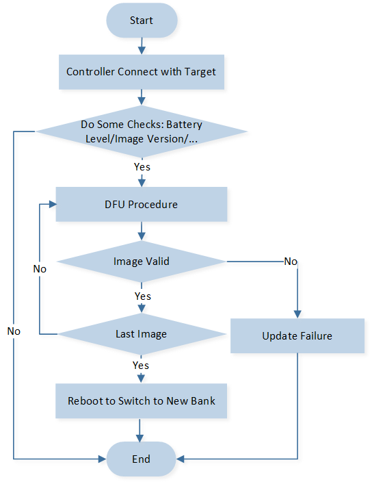
Flow of Dual Bank OTA
OTA Transmission Mechanisms
During the process of pushing an image from the OTA tool to the SoC, we designed the following mechanisms to ensure correctness and efficiency.
Buffer Check
This function can be considered a simple moving-window detection method and is enabled by default to detect transmission errors as early as possible. The steps for buffer check are as follows.
The OTA tool calculates the CRC of every N-Byte payload and sends this checksum value to the SoC after pushing the data. The size of the N-Byte payload is negotiated by the SoC and OTA tool before OTA starts.
The SoC first stores this N-Byte payload in a temporary buffer, then calculates the data checksum and compares it with the checksum value received from the OTA tool.
If the checksum values match, the SoC stores the data to the inactive bank. If they do not match, the SoC discards the data and notifies the tool, which will then retransmit the payload.
Encrypted Transmission
The OTA tool and SoC support encrypted transmission. Users can change the function app_ota_enc_setting to set it for the common SDK, and use MCUConfig Tool to set it for the headset SDK. Currently, the algorithm AES256 is supported. The OTA tool encrypts each N-Byte payload before pushing it to the SoC. The SoC decrypts the data before saving it to flash. There are the following two encryption methods.
When buffer check is enabled, the N-Byte payload will be encrypted together.
When buffer check is disabled, each packet will be encrypted separately before being pushed to the SoC.
Image Validation
The OTA tool will send the command to force the SoC to validate the entire image after an image has been fully delivered to the SoC. The checksum value (SHA256 or CRC) will be calculated and filled in the image header when the image is generated. The SoC calculates the checksum value and compares it with the value in the image header. If the two values are different, it will notify the OTA tool, and the OTA process will be considered a failure and terminated.
Image Skip and Copy
As mentioned above, to avoid image mismatches and omissions, packing whole images is mandatory. To improve upgrade efficiency, Image Skip and Image Copy mechanisms are designed to avoid unnecessary image transmission. At the beginning of the OTA process, the OTA tool will query the versions and checksums of all the images including both banks of the SoC. The flowchart for image skip and copy mechanisms is as follows.
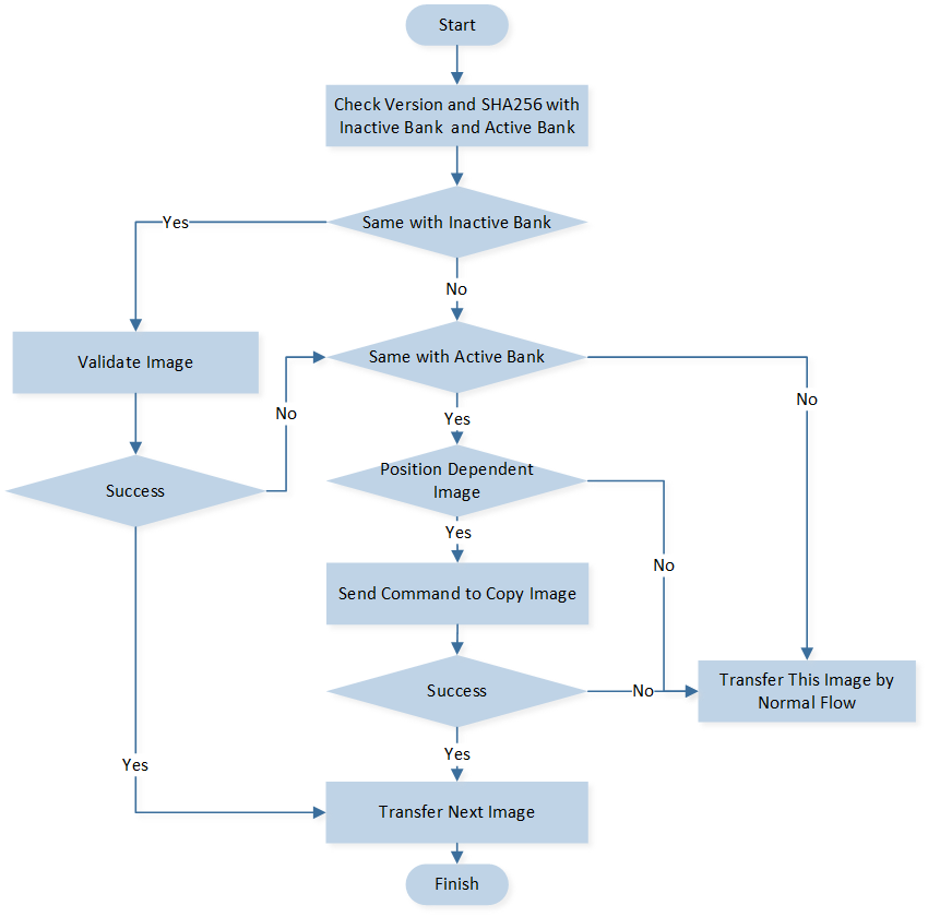
Skip and Copy Flow
Image Skip
The tool will compare each image version and SHA256 with the SoC’s inactive bank image. If both the version and SHA256 value are the same, the tool will regard the image as already existing in the inactive bank. The tool will then send a command to validate this image directly, and the SoC will check the validation and integrity of the image in the inactive bank.
If validation is successful, this image will be skipped.
If validation fails, some images can proceed to the image copy flow.
Image Copy
For some address-independent images, such as the DSP SYS image, DSP APP image, DSP configuration image and APP configuration image, the image copy mechanism may also enhance OTA efficiency. The tool compares the version and SHA256 of the address-independent images with those of the active bank images. If both the version and SHA256 value match, the tool will send a copy image command to the SoC. The SoC then copies the image from the active bank to the inactive bank and validates it. If the copy and validation are successful, this image can also be skipped. If both the image skip and image copy methods fail, the tool will proceed with the normal image data push transfer flow.
Reset and Version Re-Check
Once all the images are pushed, copied, or skipped, the OTA tool will trigger an SoC reset. SoC will reboot to select the new active bank and activate the upgraded images. OTA tool will attempt to reconnect to the SoC and query the versions of all the images in the currently active bank to verify that the OTA has taken effect. If reconnection fails, the OTA tool will display OTA failure.
OTA via GATT
An overview of the GATT profile is provided in GATT Profile Server.
GATT OTA Service Introduction
OTA attribute table is a C array defined in ota_service.c, which is used to declare two OTA-related services: OTA Service and DFU Service.
static const T_ATTRIB_APPL gatt_extended_service_table[] = {...};
OTA Service
OTA service is used to acquire device information or enter OTA mode. Service UUID is defined in the following table.
Service Name |
Service UUID |
|---|---|
OTA Service |
0x12, 0xA2, 0x4D, 0x2E, 0xFE, 0x14, 0x48, 0x8e, 0x93, 0xD2, 0x17, 0x3C, 0xFF, 0xD0, 0x00, 0x00 |
The characteristics are shown in the following table.
Characteristic Name |
Requirement |
Characteristic UUID |
Properties |
|---|---|---|---|
Enter OTA Mode |
Mandatory |
0xFFD1 |
Write Without Response |
BD Address |
Mandatory |
0xFFD2 |
Read |
Device Information |
Mandatory |
0xFFF1 |
Read |
Image Version |
Mandatory |
0xFFE0 ~ 0xFFEF |
Read |
Protocol Type |
Mandatory |
0xFFE3 |
Read |
Image Section Size |
Mandatory |
0xFFF4 ~ 0xFFF6 |
Read |
DFU Service
DFU service is used to perform the updating process. Service UUID is defined in the following table.
Service Name |
Service UUID |
|---|---|
DFU Service |
0x12, 0xA2, 0x4D, 0x2E, 0xFE, 0x14, 0x48, 0x8e, 0x93, 0xD2, 0x17, 0x3C, 0x87, 0x62, 0x00, 0x00 |
The characteristics are shown in the following table.
Characteristic Name |
Requirement |
Characteristic UUID |
Properties |
|---|---|---|---|
DFU Data |
Mandatory |
0x8763 |
Write Without Response |
DFU Control Point |
Mandatory |
0x8764 |
Write and Notify |
The opcode transmits from controller to target and the notification transmits from target to controller. All opcodes and notifications are shown in the following table.
OPCODE |
OPCODE NAME |
Notification |
Description |
|---|---|---|---|
0x01 |
|
0x01 |
Start OTA and transfer header. |
0x02 |
|
0x02 |
Receive image info. |
0x03 |
|
0x03 |
Valid the received image. |
0x04 |
|
0x04 |
Reset to active new image. |
0x05 |
|
0x05 |
Stop OTA flow and reset parameters. |
0x06 |
|
0x06 |
Get image info of target. |
0x07 |
|
0x07 |
Connection parameter update. |
0x09 |
|
0x09 |
Enable buffer check. |
0x0A |
|
0x0A |
Transfer CRC value and start check. |
0x0C |
|
0x0C |
Copy image from active bank to inactive bank. |
0x0D |
|
0x0D |
Get inactive bank image version. |
0x0E |
|
0x0E |
Get layout size of image in active bank. |
0x0F |
|
0x0F |
Check the field of SHA256. |
0x10 |
|
0x10 |
Get the release version of APP configuration image. |
Detailed OTA via GATT Flow
The detailed flow via GATT is shown in the following chart.
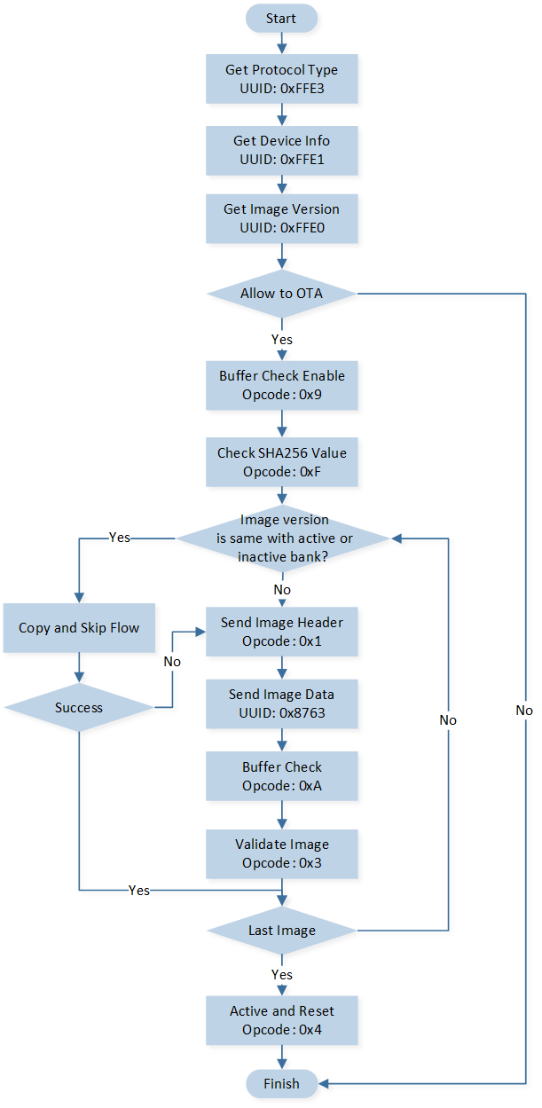
Detailed Flow via GATT
OTA via SPP
An overview of the SPP profile is provided in SPP.
SPP OTA CMD and Event Introduction
The CMD transmits from controller to target and the event transmits from target to controller. All OTA CMD and event are shown in the following table.
CMD Name |
CMD ID |
Event Name |
Event ID |
Description |
|---|---|---|---|---|
|
0x0600 |
|
0x0600 |
Get device info of target. |
|
0x0601 |
|
0x0601 |
Get image version of target. |
|
0x0602 |
|
0x0602 |
Start OTA and transfer header. |
|
0x0603 |
|
0x0603 |
Transfer data packet. |
|
0x0604 |
|
0x0604 |
Valid the received image. |
|
0x0605 |
NONE |
NONE |
Stop OTA flow and reset parameters. |
|
0x0606 |
|
0x060B |
Reset to active new image. |
|
0x0607 |
|
0x0605 |
Enable buffer check. |
|
0x0608 |
|
0x0606 |
Transfer CRC value and start check. |
|
0x0609 |
|
0x0607 |
Get image info of target. |
|
0x060A |
|
0x0608 |
Get layout size of image in active bank. |
|
0x060B |
|
0x0609 |
Get extra info of target. |
|
0x060C |
|
0x060A |
Get protocol type. |
|
0x060D |
|
0x060C |
Get the release version of APP configuration image. |
|
0x060E |
|
0x060D |
Get inactive bank image version. |
|
0x060F |
|
0x060E |
Copy image from active bank to inactive bank. |
|
0x0610 |
|
0x060F |
Check the field of SHA256. |
Detailed OTA via SPP Flow
The detailed flow via SPP is shown in the following chart.
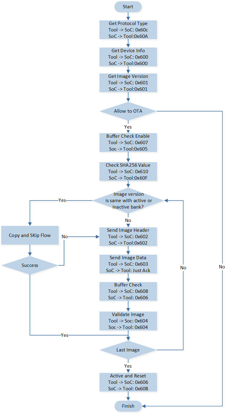
Detailed Flow via SPP
Code Overview
The OTA code overview will be introduced according to the following parts.
The OTA related code directory will be introduced in the chapter Code Directory.
The OTA related code overview will be introduced in the chapter Source Code Overview.
Code Directory
This section describes the OTA directory. The reference files directory is as follows.
└── ble_dtm_4M_bank0
    ├── include                  ROM UUID header files. Users do not need to modify it.
    ├── lib                      Includes all binary symbol files that user application is built on.
        ├── ROM.lib
        ├── upperstack_4M.lib
        ├── hal_utils.lib
        └── gap_utils.lib
    ├── cmsis                    The cmsis source code. Users do not need to modify it.
    ├── service                  LE service.
        └── ota_service.c        OTA service for GATT.
    └── app                      The application source code.
        ├── main.c               Entry of application. Initialize parameters and register application message callback.
        ├── app_task.c           Create message queue and application task.
        └── app_ota.c            OTA process for both GATT and SPP.
Source Code Overview
This section provides a description of certain portions of the source code used in the OTA demo.
OTA via GATT Source Code Overview
Register OTA service in the initialization process and increase the server number of server_init().
void app_ble_service_init(void)
{
    ...
    server_init(...);
    ota_add_service(audio_app_ota_srv_cb);
    ...
}
Generate 128-Bit UUID of OTA service by generator tool, and fill it to GATT_UUID_OTA_SERVICE[16].
Also, update the UUID at iOS/Android controller.
static const uint8_t GATT_UUID_OTA_SERVICE[16] = {...};
Process can be added to the callback function.
static T_APP_RESULT audio_app_ota_srv_cb(T_SERVER_ID service_id, void *p_data)
{
    ...
}
The OTA attribute table defined in ota_service.c is used to declare the two OTA-related services, users can add services and characteristics here.
static const T_ATTRIB_APPL gatt_extended_service_table[] = {...};
If users add a new service or characteristic to the attribute table, users can handle it in the following two functions.
static T_APP_RESULT ota_service_attr_write_cb(uint8_t conn_id, T_SERVER_ID service_id,
                                              uint16_t attr_index, T_WRITE_TYPE write_type, uint16_t length,
                                              uint8_t *p_value, P_FUN_WRITE_IND_POST_PROC *p_write_ind_post_proc)
static T_APP_RESULT ota_service_attr_read_cb(uint8_t conn_id, T_SERVER_ID service_id,
                                             uint16_t attr_index,
                                             uint16_t offset, uint16_t *p_length, uint8_t **pp_value)
New control point handle can be added to this function.
T_APP_RESULT app_ota_ble_handle_cp_req(uint8_t conn_id, uint16_t length, uint8_t *p_value)
{
    ...
}
OTA via SPP Source Code Overview
SPP OTA command and event ID can be added to the ID tables.
typedef enum
{
    ...
    EVENT_OTA_DEV_INFO = 0x0600,
    EVENT_OTA_GET_IMG_VER,
    EVENT_OTA_START,
    EVENT_OTA_PACKET,
    EVENT_OTA_VALID,
    EVENT_OTA_BUFFER_CHECK_ENABLE,
    EVENT_OTA_BUFFER_CHECK,
    EVENT_OTA_IMG_INFO,
    ...
}
typedef enum
{
    ...
    CMD_OTA_DEV_INFO = 0x0600,
    CMD_OTA_GET_IMG_VER,
    CMD_OTA_START,
    CMD_OTA_PACKET,
    CMD_OTA_VALID,
    CMD_OTA_RESET,
    CMD_OTA_ACTIVE_RESET,
    CMD_OTA_BUFFER_CHECK_ENABLE,
    CMD_OTA_BUFFER_CHECK,
    CMD_OTA_IMG_INFO,
    ...
}
SPP command handle function app_ota_cmd_handle() is added to the SPP data entrance.
void app_cmd_handler(uint8_t *cmd_ptr, uint16_t cmd_len, uint8_t cmd_path, uint8_t rx_seqn,
                     uint8_t app_idx)
{
    switch (cmd_id)
    {
        ...
    case CMD_OTA_DEV_INFO :
    case CMD_OTA_ACTIVE_BANK_VER:
    case CMD_OTA_START:
    case CMD_OTA_PACKET:
    case CMD_OTA_VALID:
    case CMD_OTA_RESET:
    case CMD_OTA_ACTIVE_RESET:
    case CMD_OTA_BUFFER_CHECK_ENABLE:
    case CMD_OTA_BUFFER_CHECK:
    case CMD_OTA_IMG_INFO:
        {
            app_ota_cmd_handle(cmd_len, cmd_ptr, app_idx);
        }
        break;
        ...
    }
}
SPP ACK handle function app_ota_cmd_ack_handle() is added to the SPP data entrance.
void app_cmd_handler(uint8_t *cmd_ptr, uint16_t cmd_len, uint8_t cmd_path, uint8_t rx_seqn,
                     uint8_t app_idx)
{
    ...
    switch (cmd_id)
    {
    case CMD_ACK:
        {
            ...
            if (cmd_path == CMD_PATH_UART)
            {
               ...
            }
            else if ((cmd_path == CMD_PATH_LE) || (cmd_path == CMD_PATH_SPP))
            {
                ...
                if (event_id == EVENT_OTA_ACTIVE_ACK)
                {
                   app_ota_cmd_ack_handle(event_id, status);
                }
                ...
            }
        }
        break;
    ...
    }
    ...
}
New SPP command handle can be added to this function.
void app_ota_cmd_handle(uint16_t length, uint8_t *p_value, uint8_t app_idx)
{
    ...
    switch (cmd_id)
    {
       ...
    }
}
Experimental Verification
After programming the application image to the EVB board, testing can be done with a mobile phone.
Prepare the Image to Update
The OTA header generate tool and image pack tool are all integrated into the MPPG Tool.
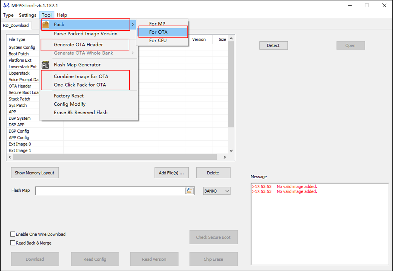
MPPG Tool
Generate OTA Header
Press the button in the image above.
Press Load Flash Laylout… to load
flash_map.ini(e.g.RTL87X3E-SDK-VX.X.X.X\bin\flash_map_config\flash_4M\flash_map.ini).Press Load RSA Key… to load RSA key (e.g.
RTL87x3E-SDK-VX.X.X.X\tool\Gadgets\default_rsa_key.pem).Select Bank0 or Bank1 and fill in the version manually to generate the OTA header file.
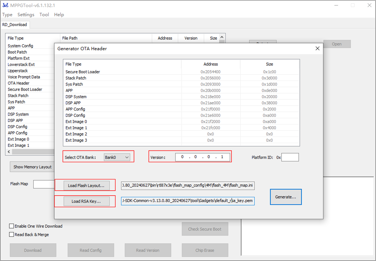
Generate OTA Header Image
Pack Whole Images
Press the button in the image above.
Press Load Flash Laylout… to load
flash_map.ini(e.g.RTL87x3E-SDK-VX.X.X.X\bin\flash_map_config\flash_4M\flash_map.ini).Select Bank0 or Bank1 to add files for packing the whole images in both banks.
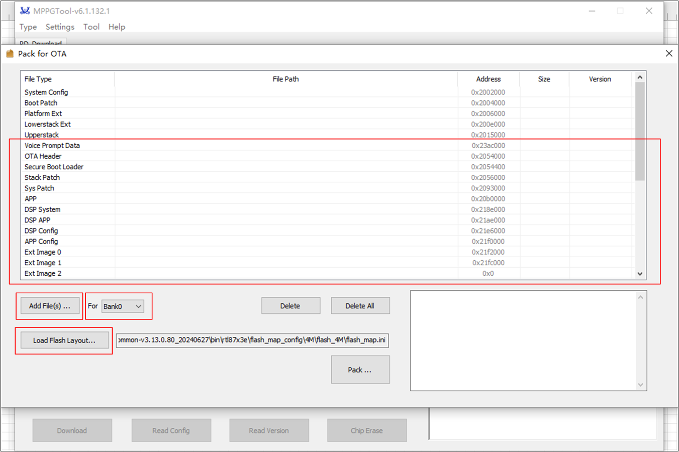
Pack Whole Image
Note
Please refer to MPPG Tool Chain User Guide available on the Realtek official website at RealMCU for details.
OTA with iOS Tool
Both Audio Connect and OTA tool can perform OTA procedures on iOS phones.
OTA with iOS Audio Connect Tool
Enable LE advertising on the LE page in MCUConfig Tool. Audio Connect identifies the SoC based on the UUID content in the LE advertising.
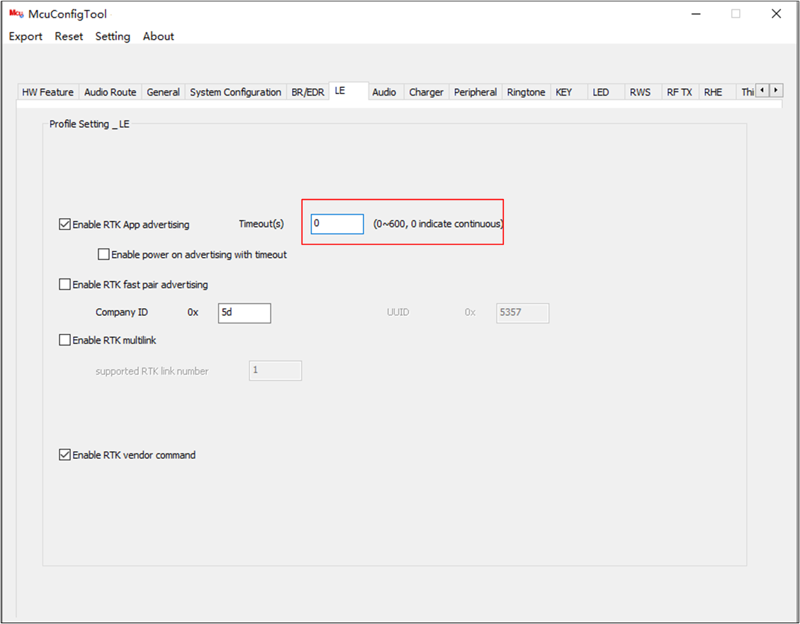
Enable LE Advertising
Connect with the target device. The device information including the image version will be shown in the UI.
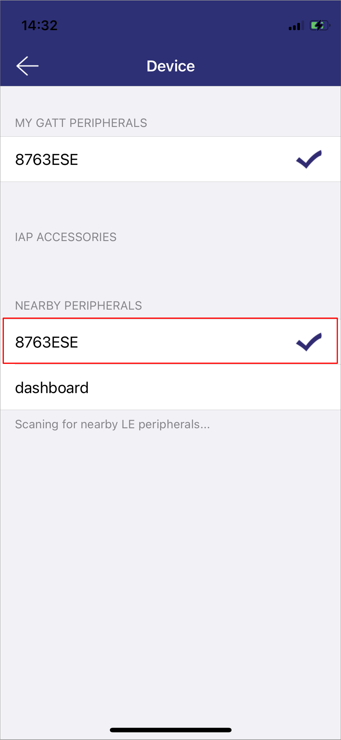
iOS Select Device
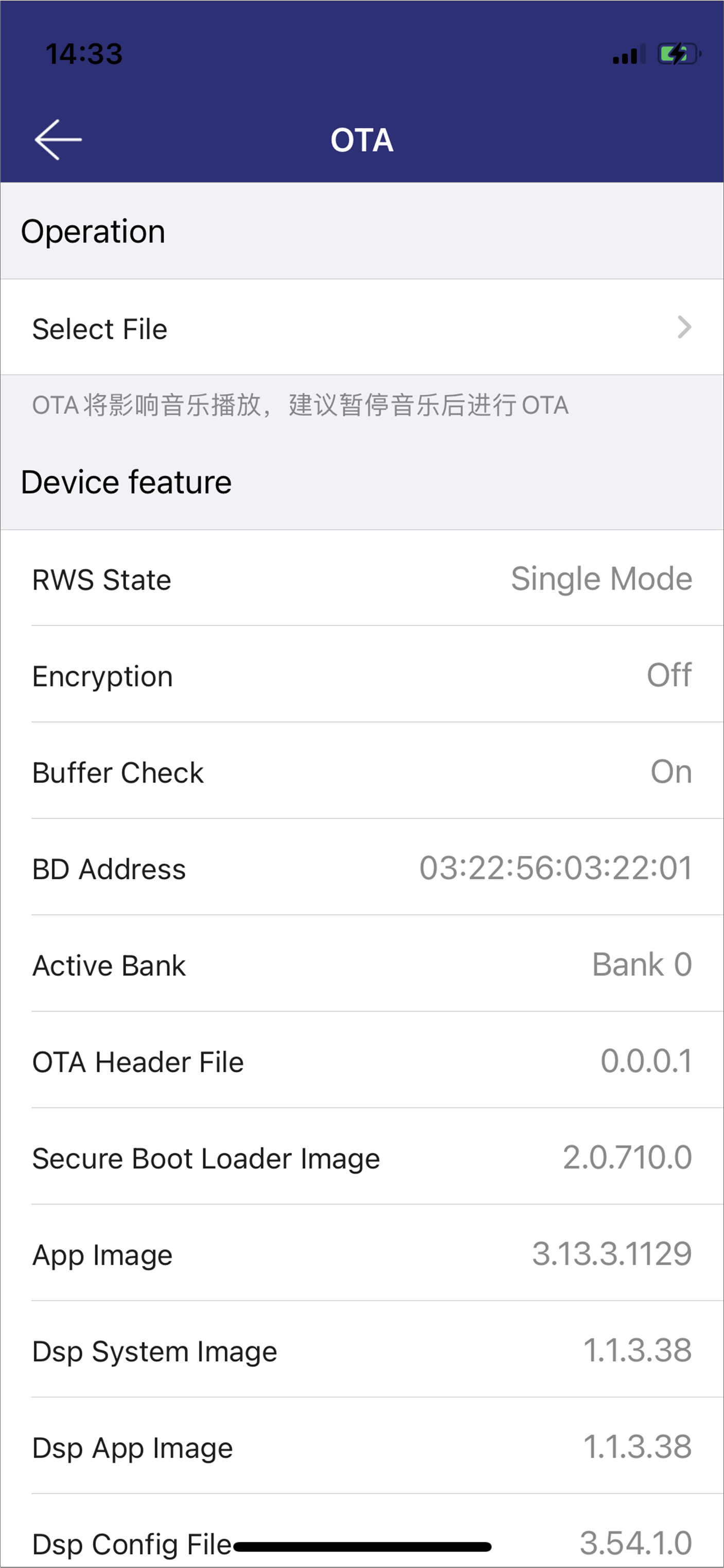
iOS Device Information
Select firmware and the firmware version will be shown below.
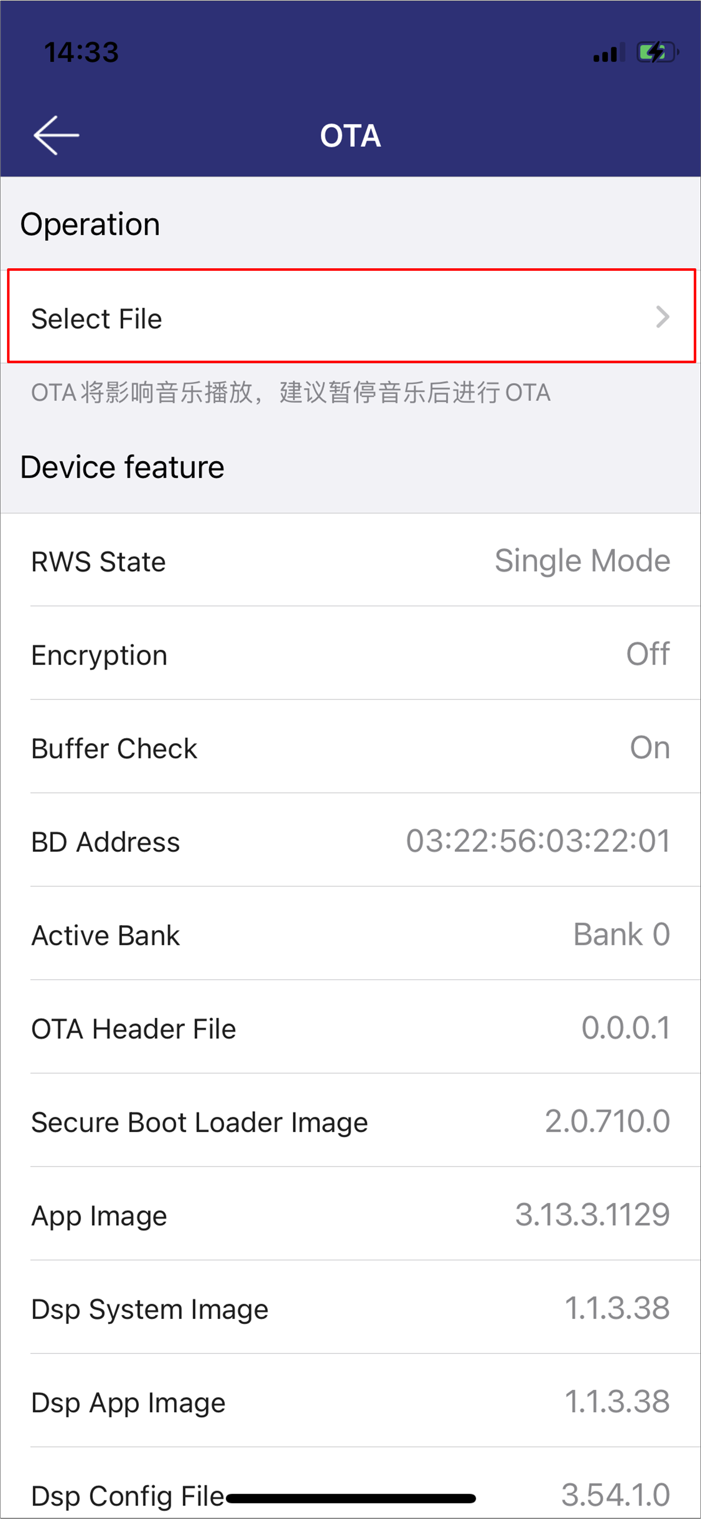
iOS Select Firmware
iOS Firmware Version
Start updating process.
iOS Updating Process
OTA with iOS OTA Tool
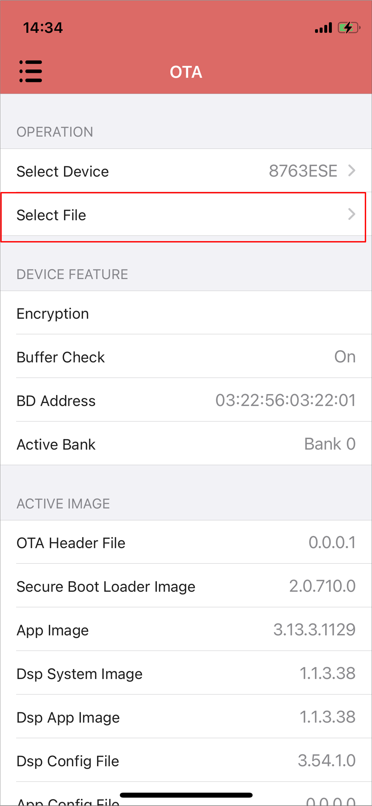
Connect with the target device. The device information including the image version will be shown in the UI.
Enable LE advertising on the LE page in MCUConfig Tool.
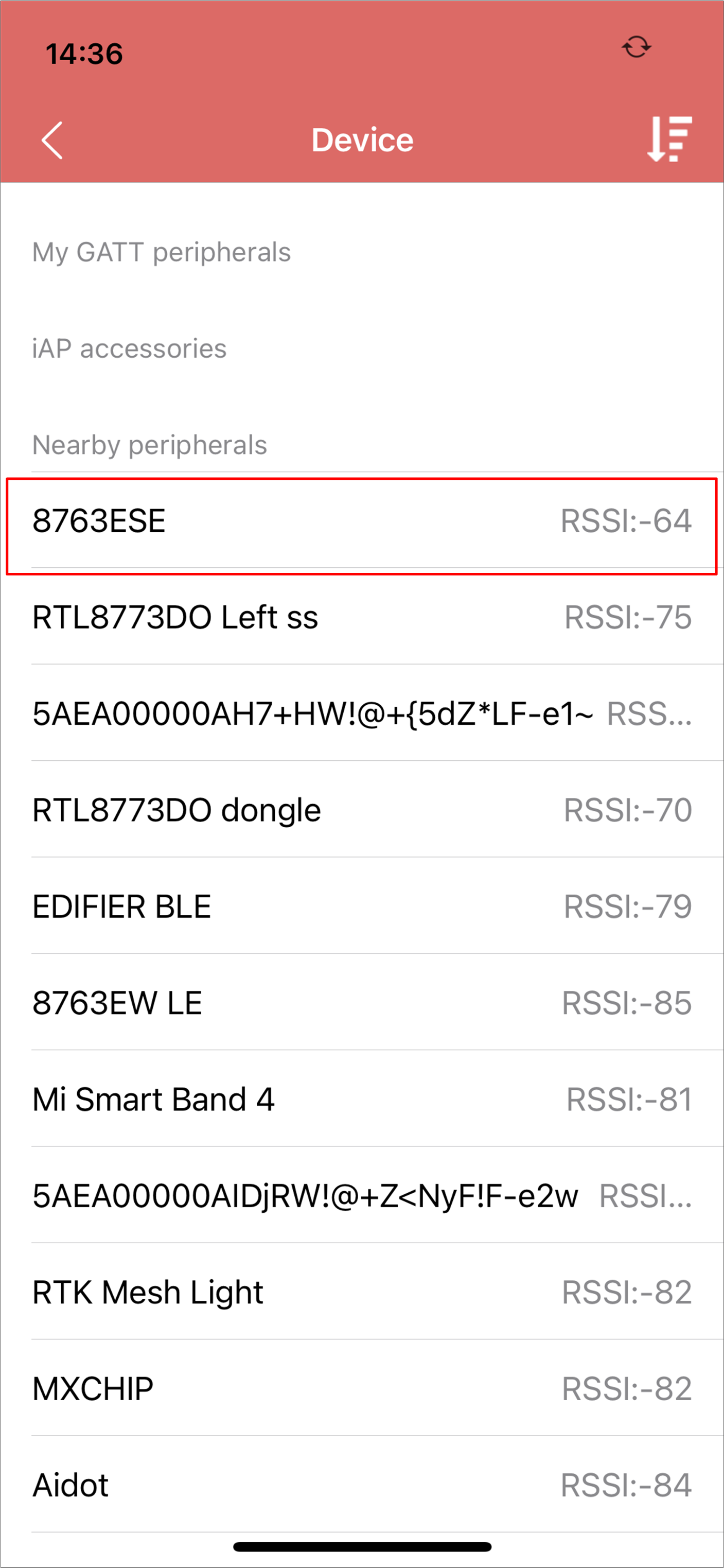
iOS Select Device
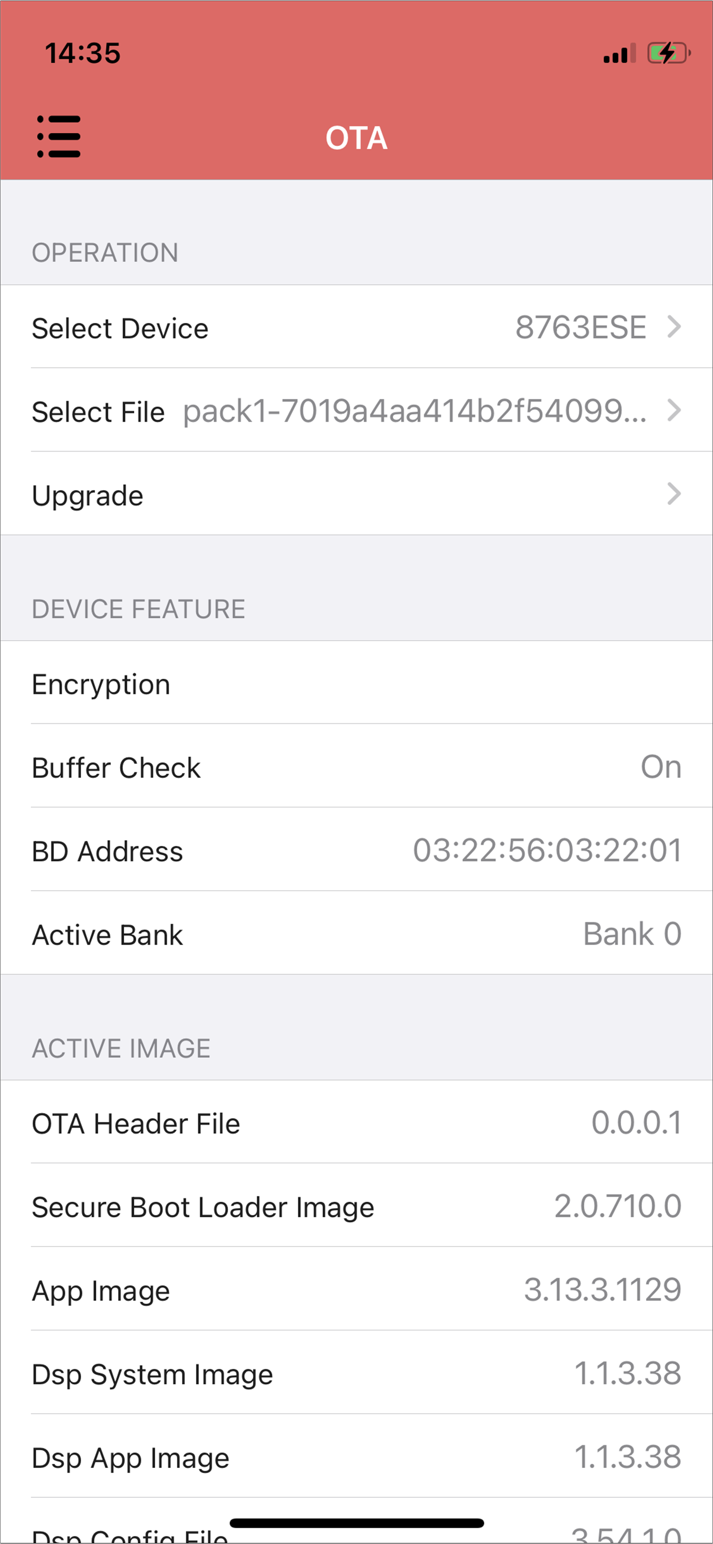
iOS Device Information
Select firmware and the firmware version will be shown below.
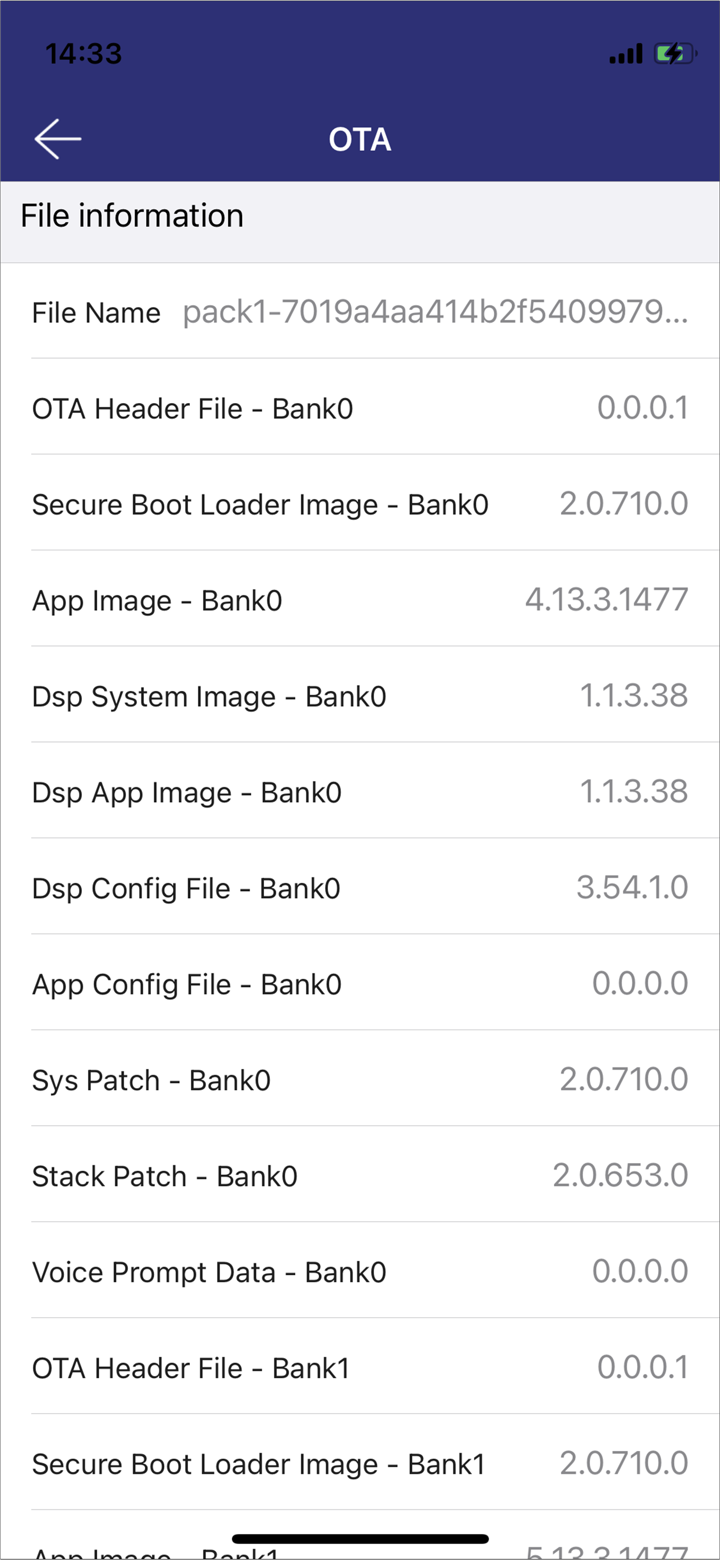
iOS Select Firmware
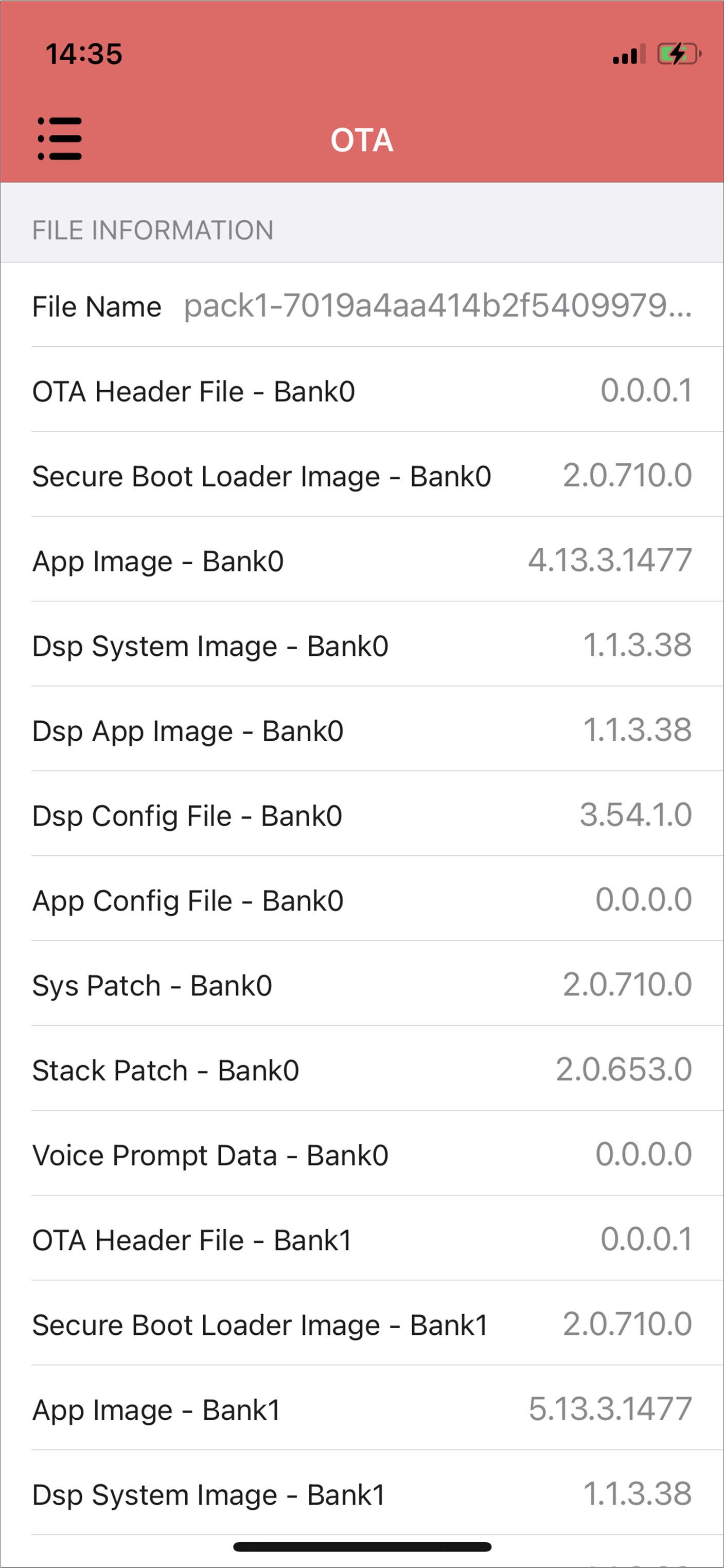
iOS Firmware Version
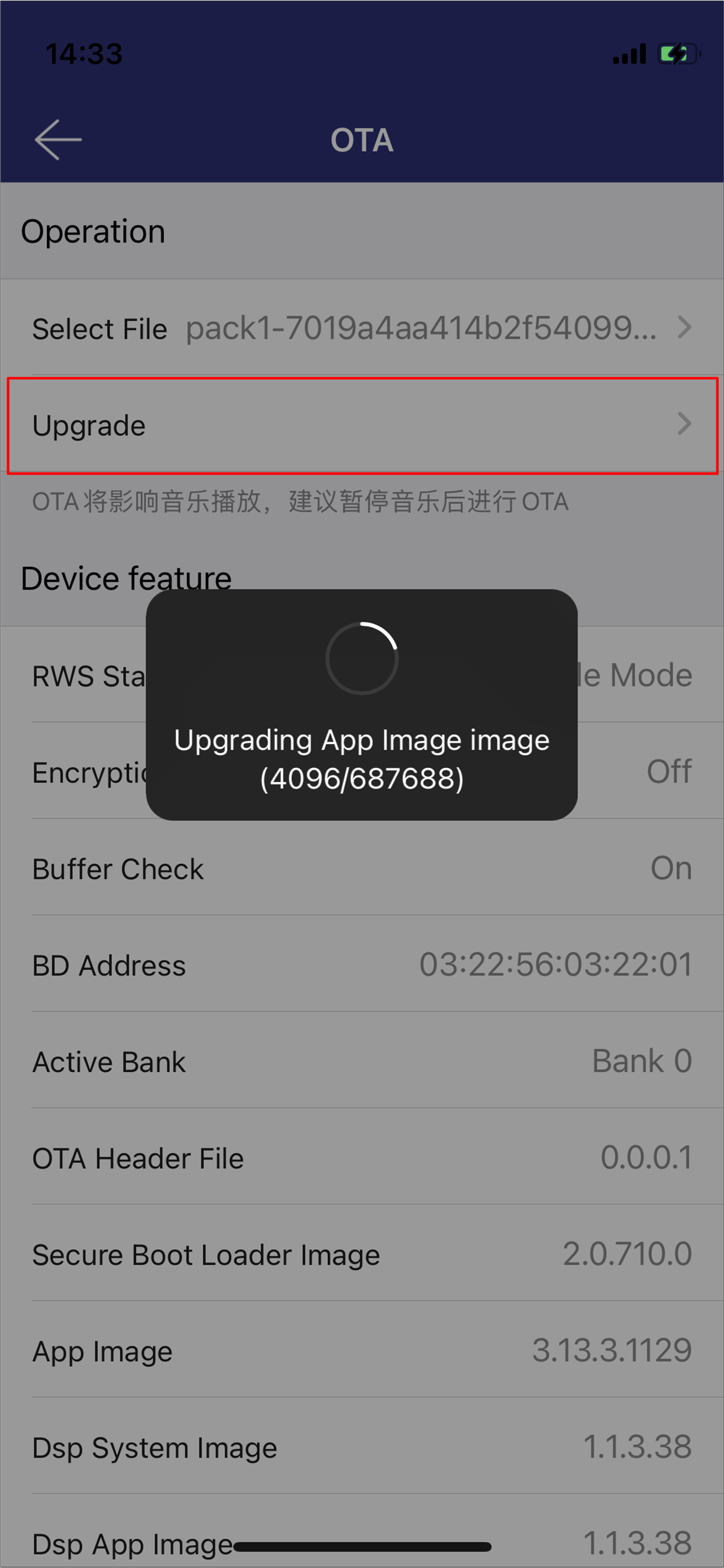
Start updating process.
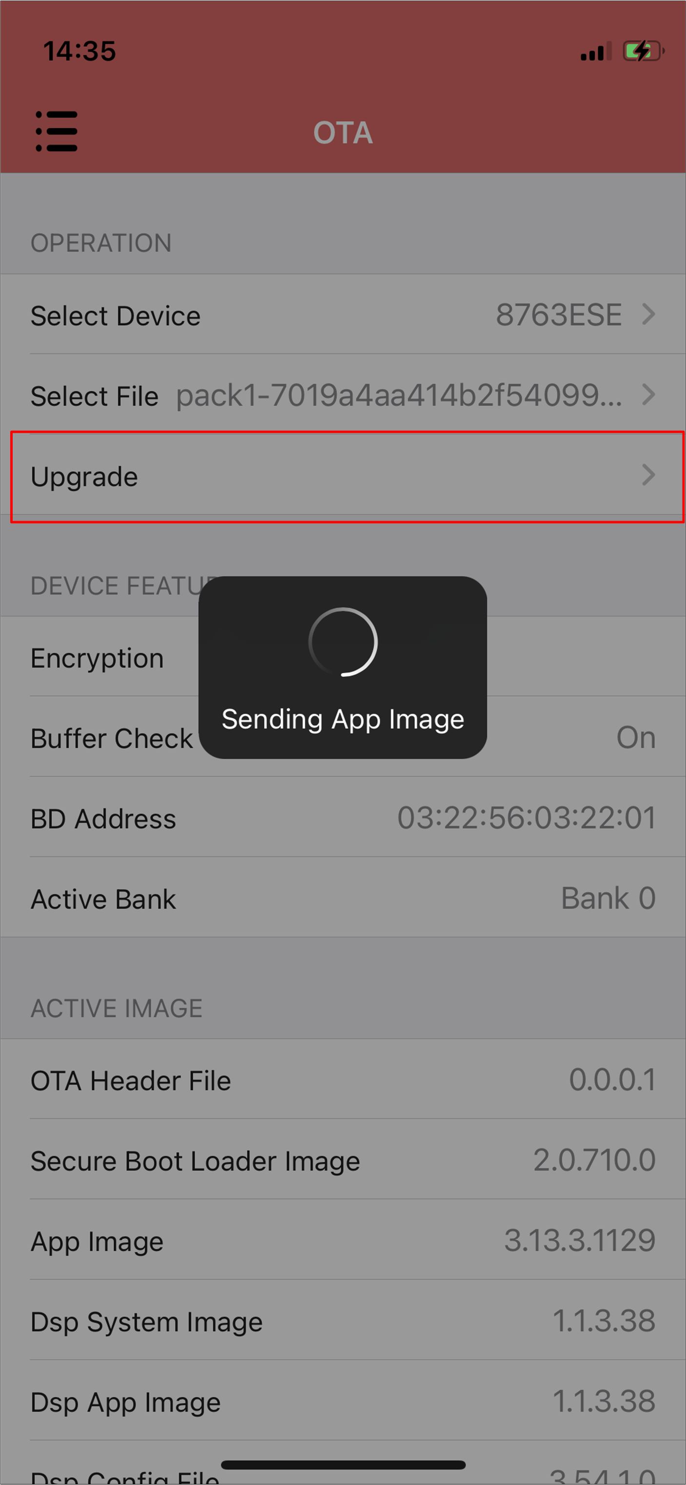
iOS Updating Process
OTA with Android Tool
Both Audio Connect and OTA tool can perform OTA procedures on Android phones.
OTA with Android Audio Connect
Let the device support the SPP profile and enter pairable mode.
Connect with the target device. The device information, including the image version, will be shown in the UI.
Android Select Device
Android Device Information
Select firmware and the firmware version will be shown below.
Android Select Firmware
Android Firmware Version
Start the updating process.
Android Updating Process
OTA with Android OTA Tool
Let the device support the SPP profile and enter pairable mode.
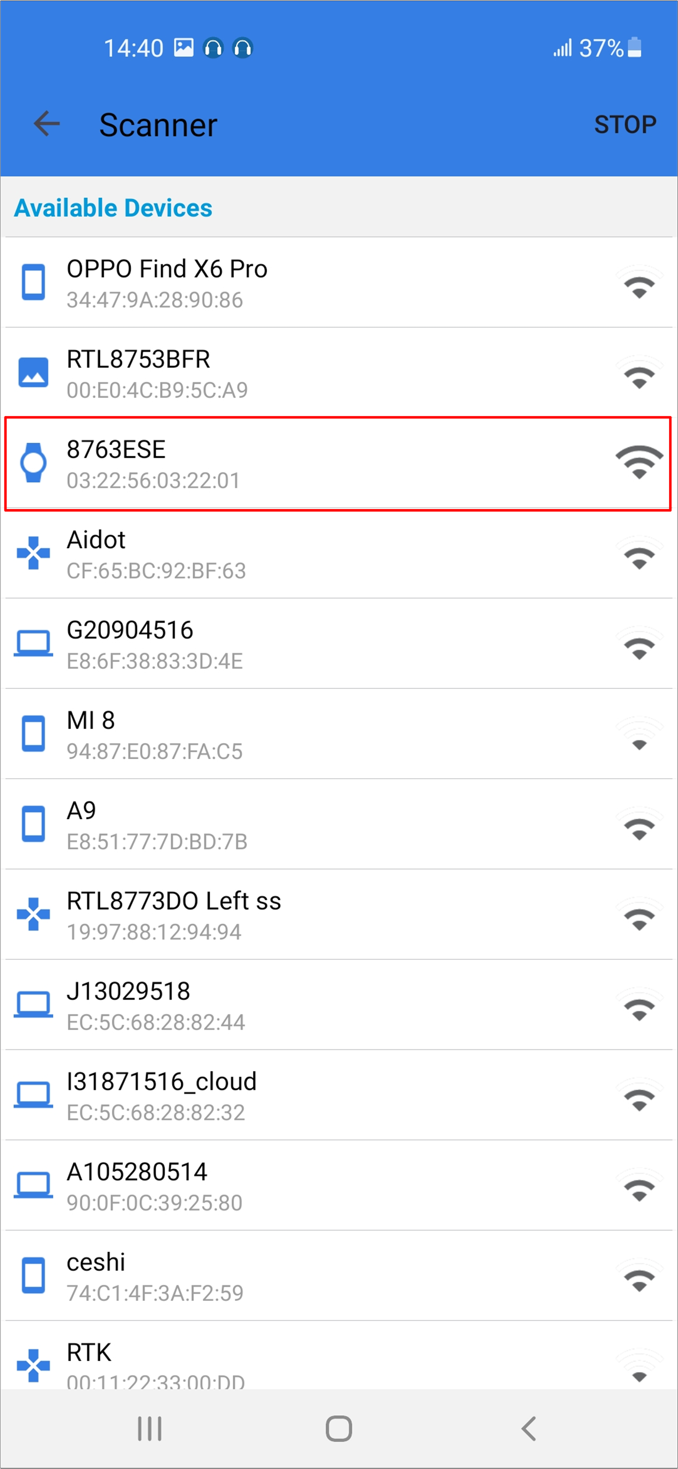
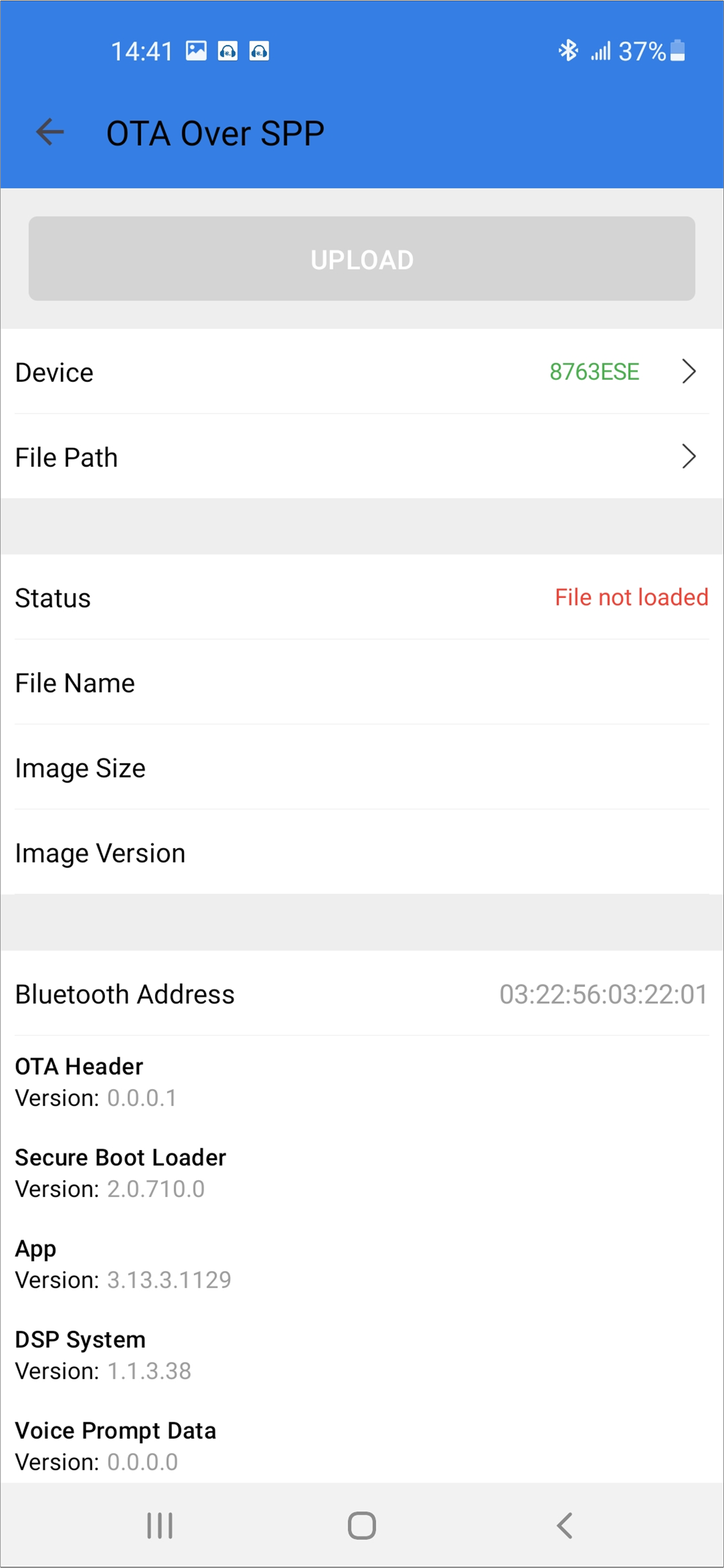
Connect with the target device. The device information, including the image version, will be shown in the UI.
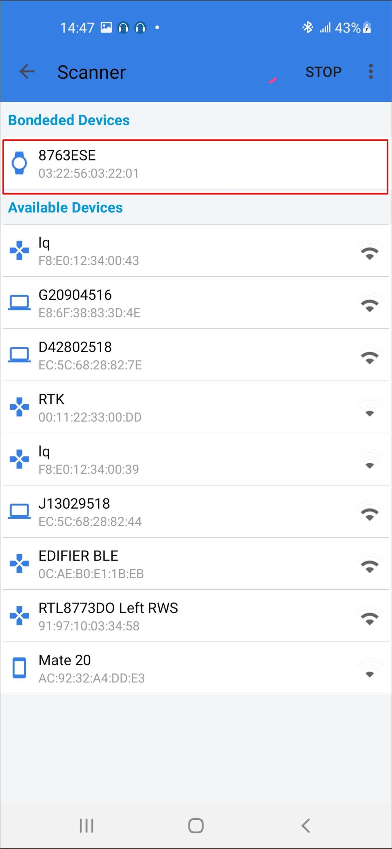
Android Select Device
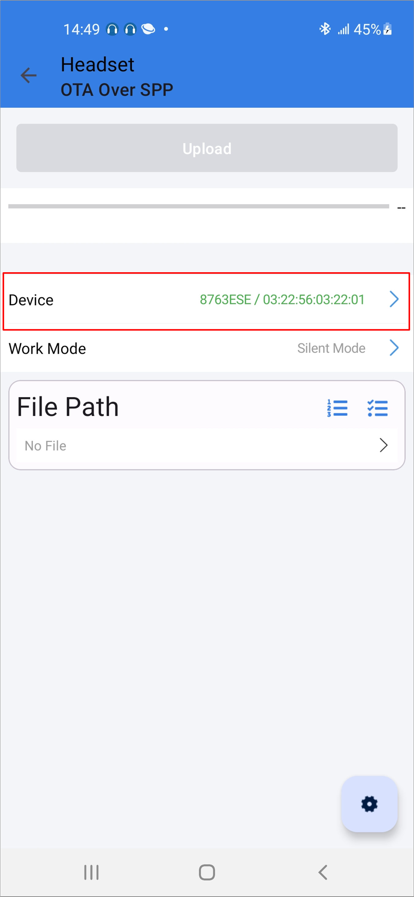
Android Device Information
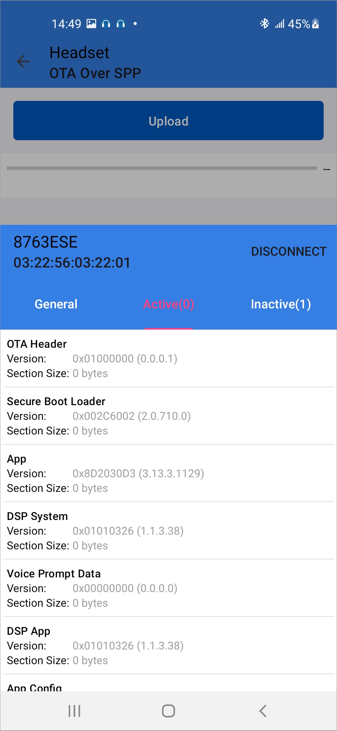
Android Device Information
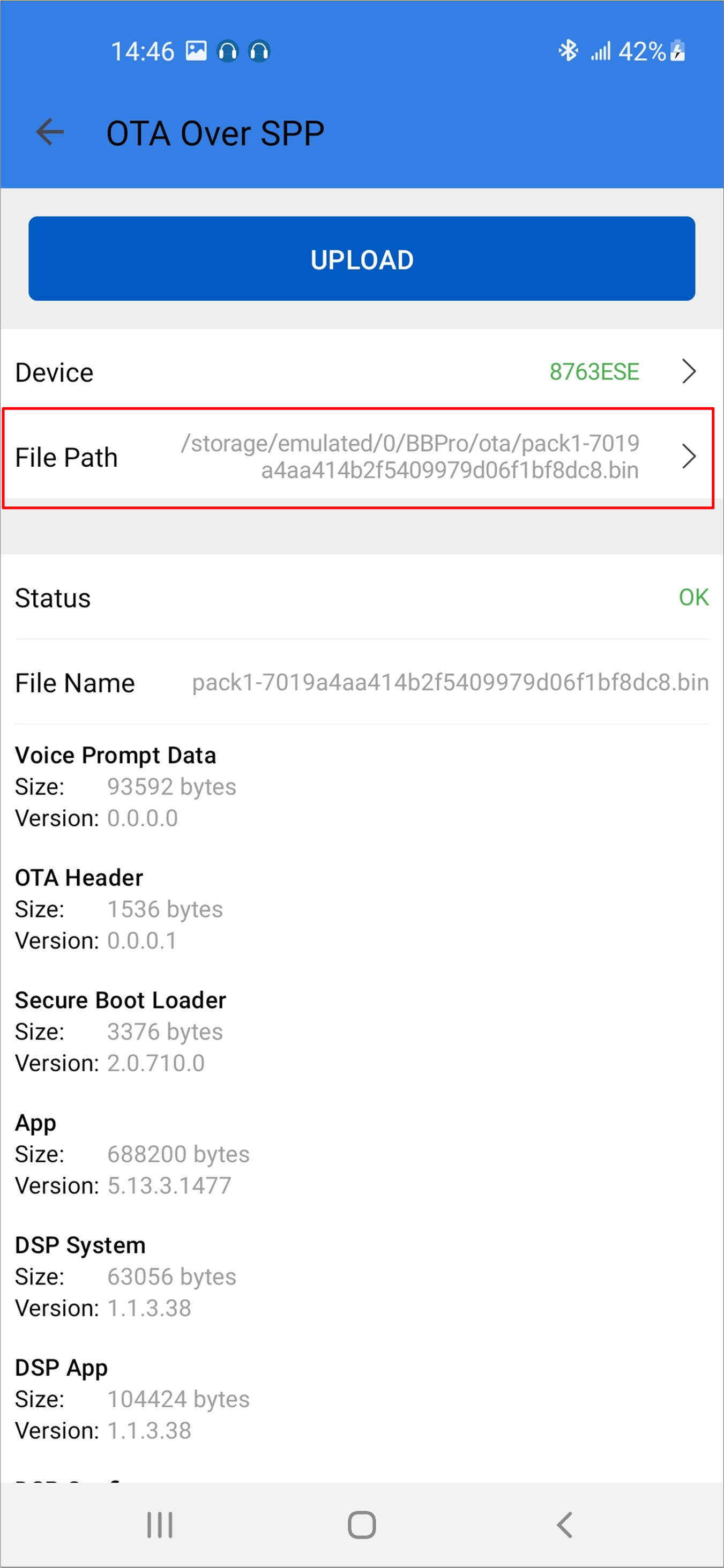
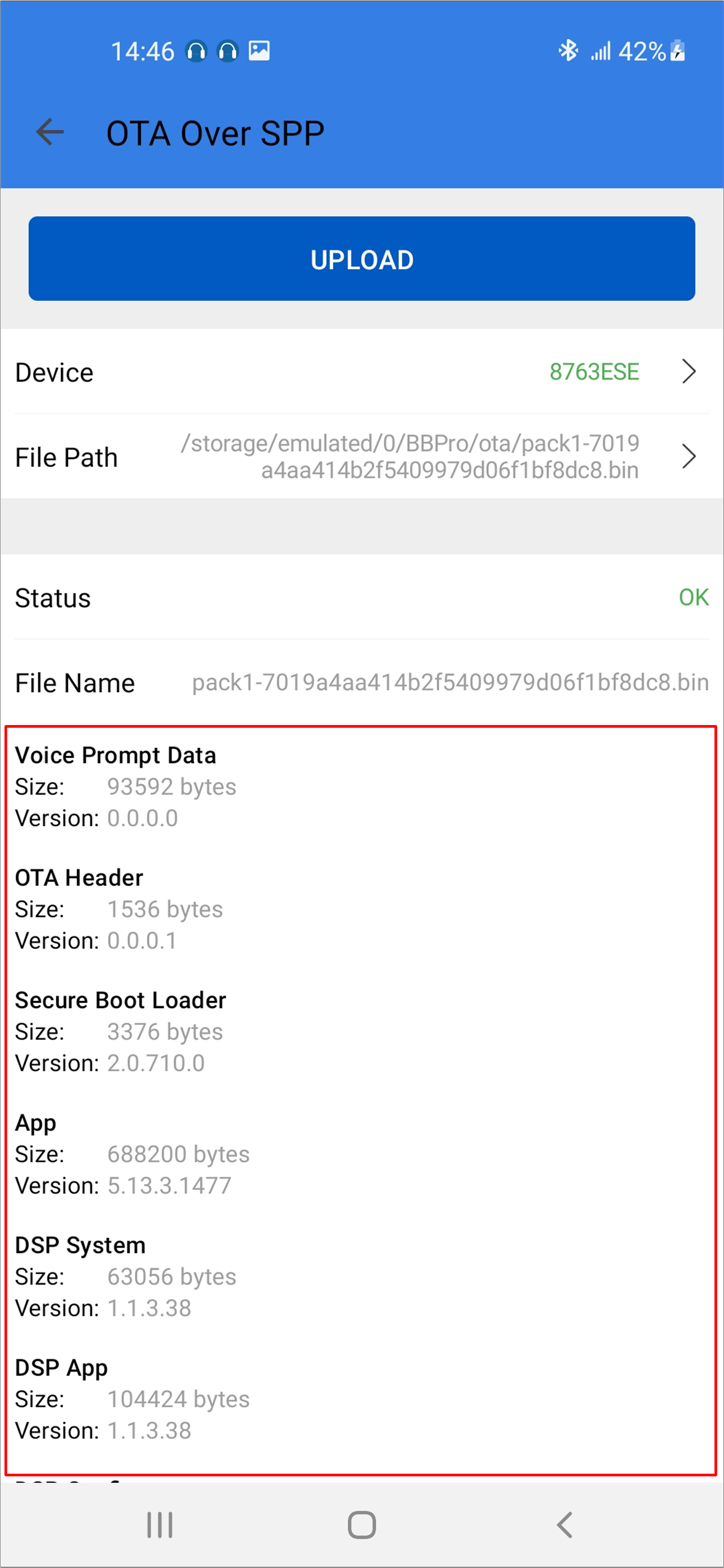
Select firmware and the firmware version will be shown below.
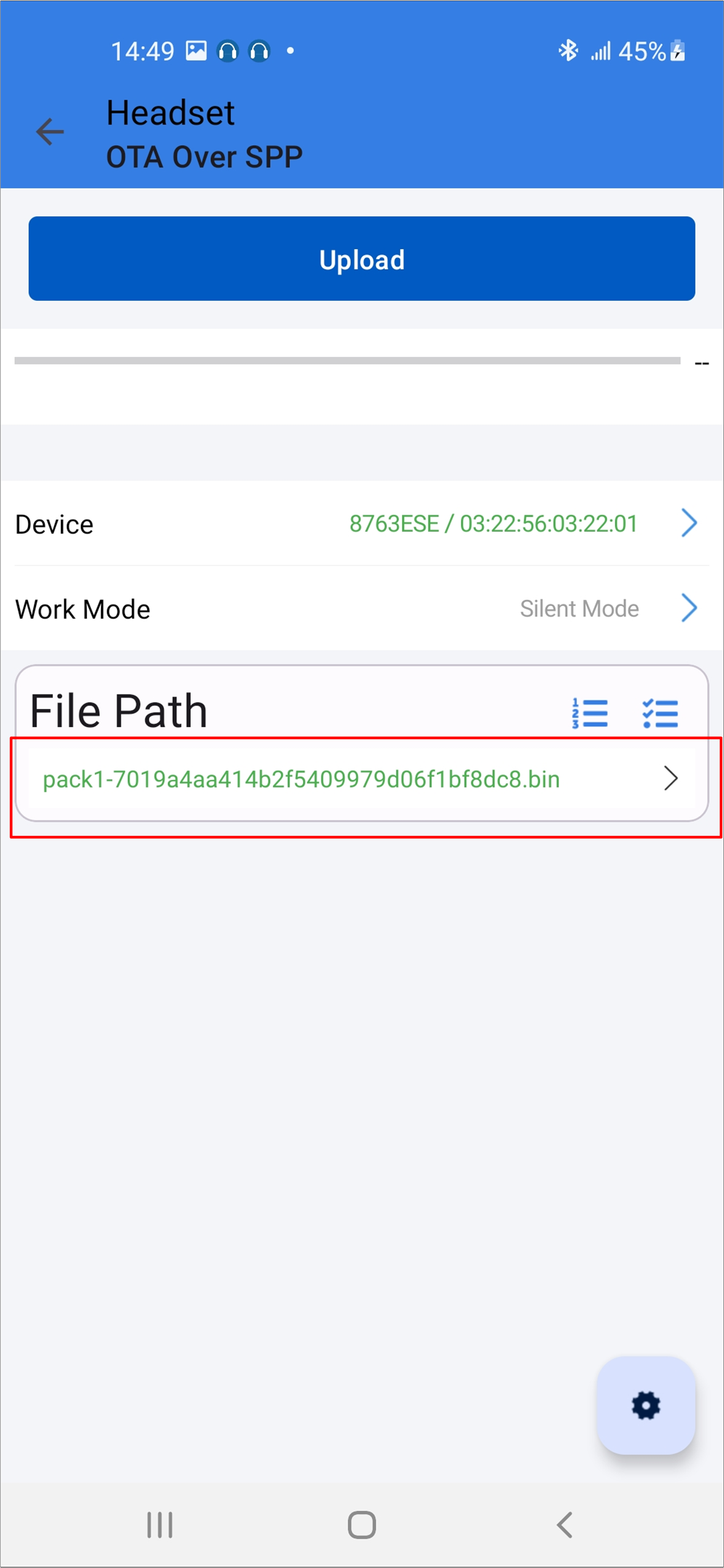
Android Select Firmware
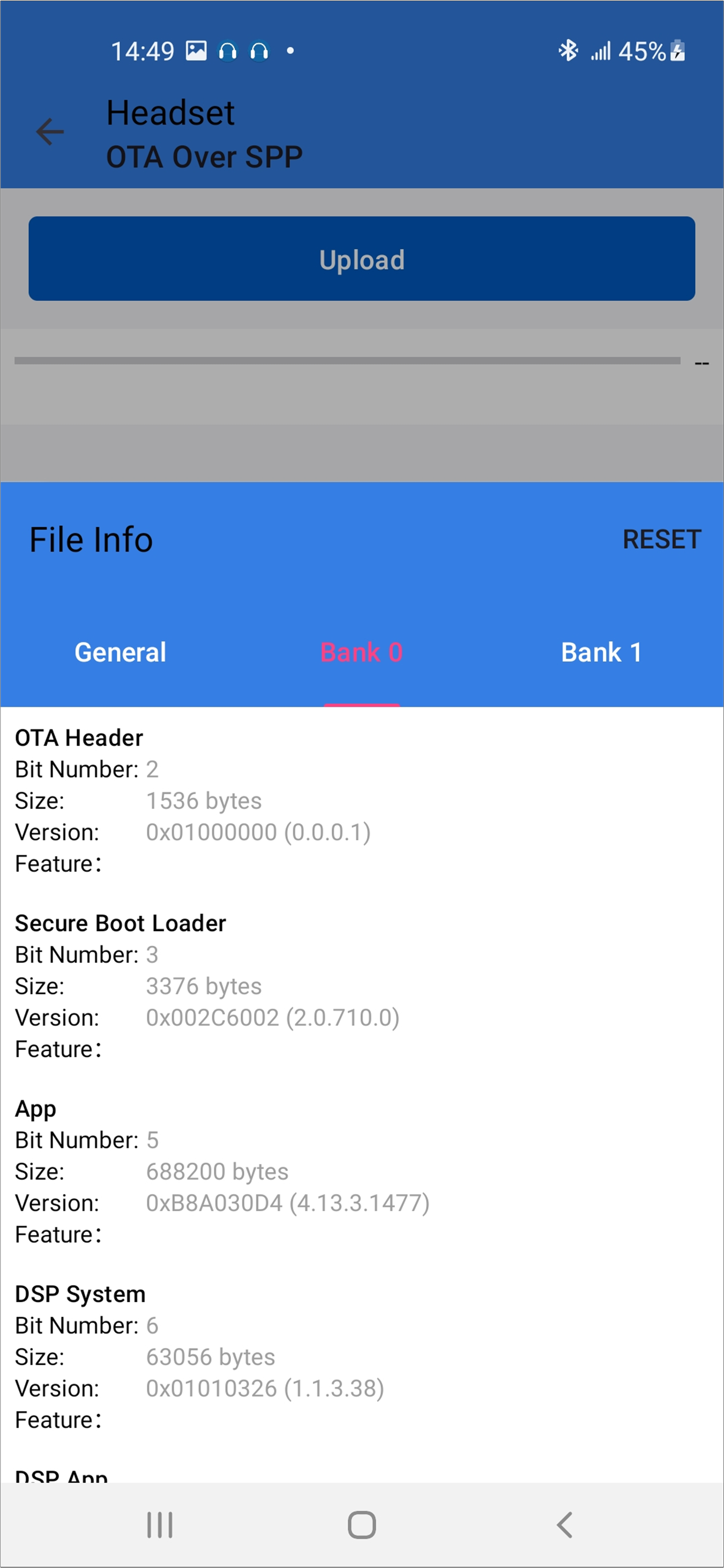
Android Firmware Version
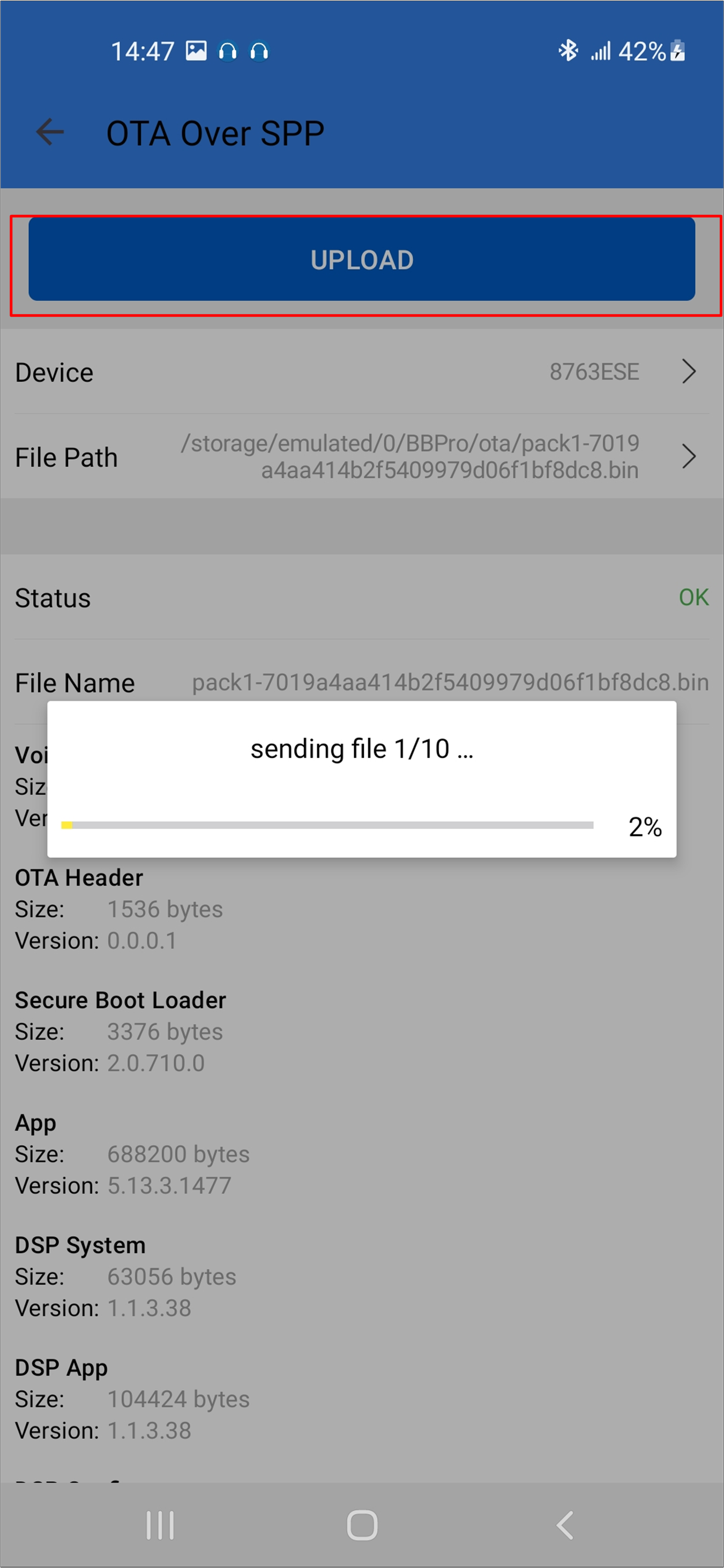
Start the updating process.
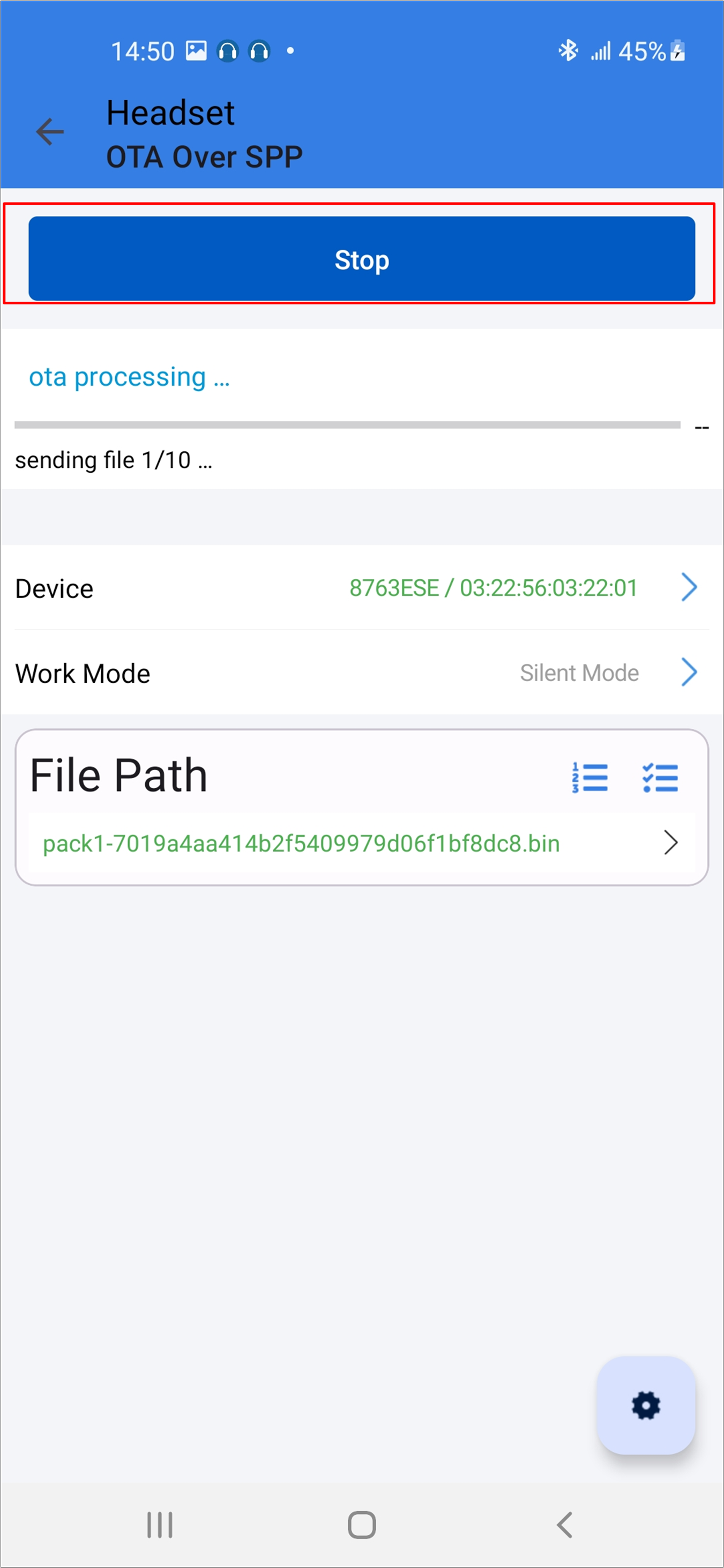
Android Updating Process