Adapter One-Wire Mode
This sample code guide is designed to help users easily and comprehensively understand UART sample. This sample code demonstrates how adapter one-wire works. When the adapter plugs in, it works as UART RX. When the adapter plugs out, it works as GPIO.
Requirements
For hardware requirements, please refer to the Requirements.
In addition, it is necessary to install serial port assistant tools such as PuTTY or UartAssist on the PC terminal.
Wiring
On EVB, TX of FT232 is connected to VADP.
RTL87x3E: On EVB, the capacitance of ADPIN on PCB needs to be replaced by 100pF.
RTL87x3D: The daughter board changes C186 to 100pf. The motherboard removes C164, DP38 and C71, and raises VAUX1 to 3.3V, connecting VIO4 to VAUX1.
The hardware connection of UART sample code is shown in the figure below.
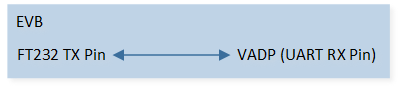
UART Sample Code Hardware Connection Diagram
Configurations
The entry function is as follows, call this function in main() to run this sample code. For more details, please refer to the Initialization.
adp_1wire_uart_demo();
Building and Downloading
For building and downloading, please refer to the Building and Downloading.
Experimental Verification
Preparation Phase
Start a PC terminal program like PuTTY or UartAssist and connect to the used COM port with the following UART settings:
Baud rate: 9600.
8 data bits.
1 stop bit.
No parity.
No hardware flow control.
Testing Phase
Press the Reset button on the EVB.
Connect TX of FT232 and VADP, the following log will be displayed in Debug Analyze, and chip can receive uart data from PC terminal. Use PC terminal program to send data to chip, the chip will print the received data in Debug Analyzer.
adp_io_in_out: adp io in
Disconnect TX of FT232 and VADP, the following log will be displayed in Debug Analyze.
adp_io_in_out: adp io out
Code Overview
This section introduces the code and process description for initialization and corresponding function implementation in the sample.
Source Code Directory
For project directory, please refer to Source Code Directory.
Source code directory:
sdk\src\sample\io_demo\adp_1wire\adp_1wire_uart_demo.c.
Initialization
Call
adp_set_debounce_time()to set ADP IO function debounce time.Call
adp_register_state_change_cb()to register ADP IO callback.
Functional Implementation
ADP IO Callback Handle
If ADP plug in, close ADP function and initialize UART, UART initialization flow is shown in the following figure:
Call
adp_close()to close ADP function.Call
UART_DeInit()to deinitialize the UART peripheral registers to their default reset values.Call
Pad_Config()andPinmux_Config()to initialize the pin.
Pad_Config(ADP_PIN, PAD_PINMUX_MODE, PAD_IS_PWRON, PAD_PULL_NONE, PAD_OUT_DISABLE, PAD_OUT_LOW);
Pinmux_Config(ADP_PIN, UART0_RX);
Call
RCC_PeriphClockCmd()to enable the UART clock and function.Initialize the UART peripheral:
Define the
UART_InitTypeDeftypeuartInitStruct, and callUART_StructInit()to pre-filluartInitStructwith default values.Modify the
uartInitStructparameters as needed. The UART initialization parameter configuration is shown in the table below.Call
UART_Init()to initialize the UART peripheral.
UART Initialization Parameters UART Hardware Parameters
Setting in the
uartInitStructUART
div
271
ovsr
10
ovsr_adj
0x24A
Parity Check
Stop Bit
Data Format
Hardware Flow Control
RX Trigger Level
Call
UART_INTConfig()to enable received data available interruptUART_INT_RD_AVAand RX idle timeout interruptUART_INT_IDLEand receiver line status interruptUART_INT_LINE_STS.Call
NVIC_Init()to enable NVIC of UART.
If ADP plug out, print the following log.
adp_io_in_out: adp io out
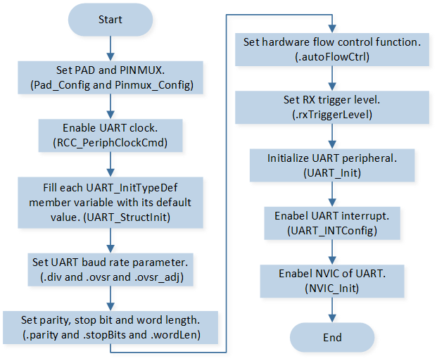
UART Initialization Flow Chart
Interrupt Handle
After the PC terminal sends a string, the chip will trigger UART interrupts. UART interrupt handle flow is shown in the following figure.
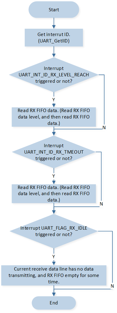
UART Interrupt Handle Flow
Call
UART_GetIID()to get the interrupt ID.If the RX FIFO level reached the RX trigger level set in
UART_InitTypeDef::rxTriggerLevel,UART_INT_ID_RX_LEVEL_REACHinterrupt first is triggered first:Call
UART_GetRxFIFOLen()to get the data length in RX FIFO.Call
UART_ReceiveData()to receive data from RX FIFO.
There’s at least 1 UART data in the RX FIFO but no character has been input to the RX FIFO or read from it for the last time of 4 characters.
UART_INT_ID_RX_TMEOUTinterrupt is triggered:Call
UART_GetRxFIFOLen()to get the data length in RX FIFO.Call
UART_ReceiveData()to receive data from RX FIFO.
If No data is received in RX idle timeout time after the RX FIFO is empty (data is received before), the
UART_FLAG_RX_IDLEinterrupt is triggered:Call
UART_GetFlagState()to checkUART_FLAG_RX_IDLEinterrupt flag state.Call
UART_INTConfig()to disableUART_INT_IDLEinterrupt.Call
UART_INTConfig()to enableUART_INT_IDLEinterrupt.
When parity error or frame error or break error or overrun error occurs,
UART_INT_ID_LINE_STATUSinterrupt is triggered:Call
UART_GetLineStatus()to get line status.If break error occurs:
Call
UART_INTConfig()to disable RX idle timeout interruptUART_INT_IDLE.Call
UART_INTConfig()to disable received data available interruptUART_INT_RD_AVA.Call
UART_INTConfig()to disable receiver line status interruptUART_INT_LINE_STS.Call
adp_open()to open ADP function.