UART RX Data in GDMA Mode
This sample code guide is designed to help users easily and comprehensively understand UART sample. This sample demonstrates how UART receives data in GDMA mode. This sample code demonstrates the communication between chip and PC terminal. PC terminal transmits some data to chip.
Requirements
For hardware requirements, please refer to the Requirements.
In addition, it is necessary to install serial port assistant tools such as PuTTY or UartAssist on the PC terminal.
Wiring
Connect P3_1 (UART TX Pin) to the RX pin of the FT232 and P3_0 (UART RX Pin) to the TX pin of the FT232.
The hardware connection of UART sample code is shown in the figure below.
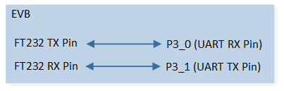
UART Sample Code Hardware Connection Diagram
Configurations
The following macros can be configured to modify pin definitions.
#define UART_TX_PIN P3_1#define UART_RX_PIN P3_0
The entry function is as follows, call this function in
main()to run this sample code. For more details, please refer to the Initialization.uart_rx_dma();
Building and Downloading
For building and downloading, please refer to the Building and Downloading.
Experimental Verification
Preparation Phase
Start a PC terminal program like PuTTY or UartAssist and connect to the used COM port with the following UART settings:
Baud rate: 3000000.
8 data bits.
1 stop bit.
No parity.
No hardware flow control.
Testing Phase
Press the Reset button on the EVB, chip starts with transmitting ### Welcome to use RealTek Bumblebee ###rn. Observe that the string appears on the PC terminal program.
Use PC terminal program to send data to chip. After the chip receives the data, it will print the amount of received data in Debug Analyzer and the data will be stored in array
uart_receive_buf.data_uart_handler: rx_count xx
Code Overview
This section introduces the code and process description for initialization and corresponding function implementation in the sample.
Source Code Directory
For project directory, please refer to Source Code Directory.
Source code directory:
sdk\src\sample\io_demo\gdma\uart_idle_rx\uart_rx_dma.c.
UART Initialization
The initialization flow for peripherals can refer to Initialization Flow.
UART initialization flow is shown in the following figure.
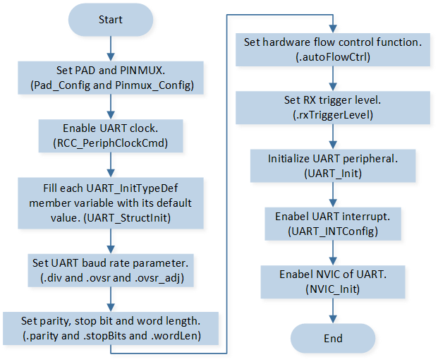
UART Initialization Flow Chart
Call
Pad_Config()andPinmux_Config()to initialize the pin.static void board_dma_uart_init(void) { Pad_Config(UART_TX_PIN, PAD_PINMUX_MODE, PAD_IS_PWRON, PAD_PULL_NONE, PAD_OUT_DISABLE, PAD_OUT_LOW); Pad_Config(UART_RX_PIN, PAD_PINMUX_MODE, PAD_IS_PWRON, PAD_PULL_UP, PAD_OUT_DISABLE, PAD_OUT_LOW); Pinmux_Config(UART_TX_PIN, UART0_TX); Pinmux_Config(UART_RX_PIN, UART0_RX); }
Call
UART_DeInit()to deinitialize the UART.Call
RCC_PeriphClockCmd()to enable the UART clock and function.Initialize the UART peripheral:
Define the
UART_InitTypeDeftypeuartInitStruct, and callUART_StructInit()to pre-filluartInitStructwith default values.Modify the
uartInitStructparameters as needed. The UART initialization parameter configuration is shown in the table below.Call
UART_Init()to initialize the UART peripheral.
UART Initialization Parameters UART Hardware Parameters
Setting in the
uartInitStructUART
div
1
ovsr
8
ovsr_adj
0x492
Parity Check
Stop Bit
Data Format
Hardware Flow Control
RX Trigger Level
29
GDMA Enable
RX Waterlevel
1
RX GDMA Enable
Call
UART_INTConfig()to enable RX idle timeout interruptUART_INT_IDLEand receiver line status interruptUART_INT_LINE_STS.Call
NVIC_Init()to enable NVIC of UART.
GDMA Initialization
GDMA initialization flow is shown in the following figure.
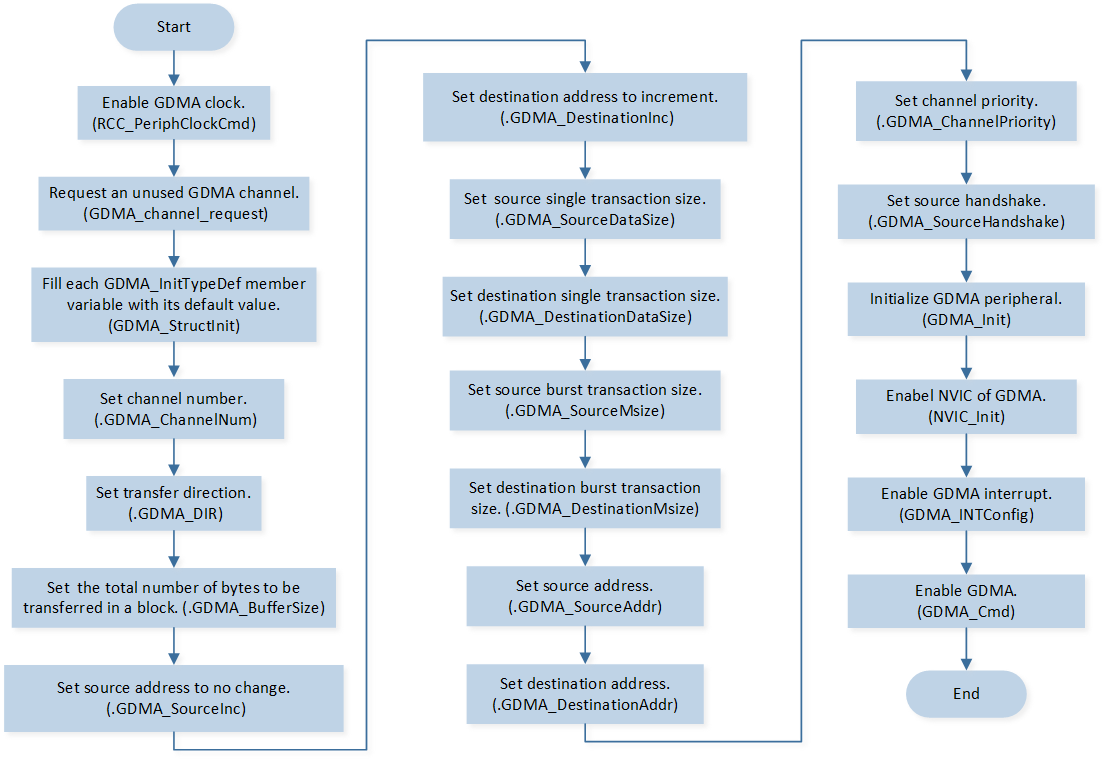
GDMA Initialization Flow Chart
Call
RCC_PeriphClockCmd()to enable the GDMA clock and function.Call
GDMA_channel_requestto request an unused GDMA channel.Initialize the GDMA peripheral:
Define the
GDMA_InitTypeDeftypeGDMA_InitStruct, and callGDMA_StructInit()to pre-fillGDMA_InitStructwith default values.Modify the
GDMA_InitStructparameters as needed. The GDMA initialization parameter configuration is shown in the table below.Call
GDMA_Init()to initialize the GDMA peripheral.
GDMA Initialization Parameters GDMA Hardware Parameters
Setting in the
GDMA_InitStructVariablesGDMA
Channel Num
UART_RX_DMA_CHANNEL_NUMTransfer Direction
Buffer Size
128
Source Address Increment or Fix
Destination Address Increment or Fix
Source Data Size
Destination Data Size
Source Burst Transaction Length
Destination Burst Transaction Length
Source Address
(uint32_t)(&(UART0->RB_THR))Destination Address
(uint32_t)(uart_receive_buf)Source Handshake
Call
NVIC_Init()to enable NVIC of GDMA.Call
GDMA_INTConfig()to enable GDMA transfer complete interruptGDMA_INT_Transfer.Call
GDMA_Cmd()to enable GDMA.
Functional Implementation
Send Data
Transmit ### Welcome to use RealTek Bumblebee ###rn to the PC terminal:
Call
UART_SendData()to continuously write data to the TX FIFO. The number of data continuously written to the TX FIFO must not exceed the size of the TX FIFO.Call
UART_GetFlagState()to checkUART_FLAG_THR_EMPTYflag state and wait for transmitter holding register to be empty.Repeat the above process to send all data to TX FIFO in batches.
UART Interrupt Handle
After the PC terminal sends a string, the chip will trigger UART interrupts.
Call
UART_GetIID()to get the interrupt ID.If No data is received in RX idle timeout time after the RX FIFO is empty (data is received before), the
UART_FLAG_RX_IDLEinterrupt is triggered:Call
UART_GetFlagState()to checkUART_FLAG_RX_IDLEinterrupt flag state.Call
UART_ClearINT()to clearUART_FLAG_RX_IDLEinterrupt.Call
GDMA_GetChannelStatus()to get the status of the GDMA channel used by the UART.If the status of the GDMA channel used by the UART is not free, call
GDMA_SuspendCmd()to suspend GDMA transmission from the source.Call
GDMA_GetFIFOStatus()to check whether GDMA FIFO is empty and wait for GDMA FIFO is empty.Call
GDMA_GetTransferLen()to get GDMA transfer data length.Call
GDMA_Cmd()to disable the GDMA channel used by the UART.Call
GDMA_SetDestinationAddress()to set GDMA transmission destination address.Call
GDMA_SuspendCmd()to suspend GDMA transmission from the source.Call
GDMA_Cmd()to enable the GDMA channel used by the UART.
When parity error or frame error or break error or overrun error occurs,
UART_INT_ID_LINE_STATUSinterrupt is triggered:Call
UART_INTConfig()to disable receiver line status interruptUART_INT_LINE_STS.Call
UART_GetLineStatus()to get line status.Call
UART_INTConfig()to enable receiver line status interruptUART_INT_LINE_STS.
GDMA Interrupt Handle
When GDMA transfer completion to the destination, GDMA_INT_Transfer interrupt is triggered:
Call
GDMA_ClearINTPendingBit()to clearGDMA_INT_Transferinterrupt.