Timer Interrupt
该示例使用 TIM,实现每 1 秒产生一次超时中断。
为了便于观察,在 EVB 板上将 P0_0 引脚连接到 LED0。
当计时时间达到 1 秒时,会触发中断。在中断处理函数中,程序会翻转 P0_0 引脚的电平,改变 GPIO 的输出极性,进而实现 LED0 每秒闪烁一次的效果。
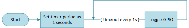
Timer 超时框图
用户可以通过不同的宏配置来修改引脚信息,定时时间等。具体宏配置详见 配置选项。
环境需求
该示例的环境需求,可参考 环境需求。
硬件连线
连接 P0_0 和 LED0 小灯。
LED 驱动电路如下图所示。
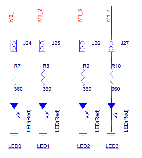
LED 驱动电路图
配置选项
-
可配置如下宏修改引脚定义。
#define OUTPUT_PIN          P0_0
#define GPIO_PIN            GPIO_GetPin(OUTPUT_PIN)
#define GPIO_PORT           GPIO_GetPort(OUTPUT_PIN)
-
可配置如下宏修改定时时间。
#define TIME_UINT            40                            /*< 40M source clock is divided to get unit: 1 us */
#define TIME_TIMING          1000000                       /*< Set this macro to 1000000, with a timer duration of 1 s. the unit for this macro is in microseconds (us). */
#define TIMER_PERIOD         (TIME_TIMING * TIME_UINT - 1)
编译和下载
该示例的编译和下载流程,可参考 编译和下载。
测试验证
-
当 EVB 启动后,在 Debug Analyzer 工具内观察如下 log。
Start timer interrupt test!
使能 TIM 后,每计时时间达到 1s,会触发 TIM 中断,在中断函数内翻转 P0_0 输出电平,可观察到 LED0 每 1 秒闪烁一次。
代码介绍
该章节主要介绍示例中的初始化和相应功能实现的代码和流程说明
源码路径
工程文件和源码路径如下:
工程路径:
sdk\samples\peripheral\timer\timer_interrupt\proj源码路径:
sdk\samples\peripheral\timer\timer_interrupt\src
初始化
外设的初始化流程可参考 General Introduction 中的 初始化流程 部分。
-
调用
Pad_Config()与Pinmux_Config(),配置对应引脚的 PAD 和 PINMUX 。void board_gpio_init(void) { Pad_Config(OUTPUT_PIN, PAD_PINMUX_MODE, PAD_IS_PWRON, PAD_PULL_NONE, PAD_OUT_ENABLE, PAD_OUT_HIGH); Pinmux_Config(OUTPUT_PIN, DWGPIO); }
调用
RCC_PeriphClockCmd(),开启 GPIO 时钟。-
对 GPIO 外设进行初始化:
定义
GPIO_InitTypeDef类型GPIO_InitStruct,调用GPIO_StructInit()将GPIO_InitStruct预填默认值。根据需求修改
GPIO_InitStruct参数,GPIO 的初始化参数配置如下表。调用GPIO_Init(),初始化 GPIO 外设。
GPIO Hardware Parameters |
Setting in the |
GPIO |
|---|---|---|
GPIO pin |
|
|
GPIO direction |
调用
RCC_PeriphClockCmd(),开启 TIM 时钟。-
对 TIM 外设进行初始化:
定义
TIM_TimeBaseInitTypeDef类型TIM_InitStruct,调用TIM_StructInit()将TIM_InitStruct预填默认值。根据需求修改
TIM_InitStruct参数,TIM 的初始化参数配置如下表。调用TIM_TimeBaseInit(),初始化 TIM 外设。调用
NVIC_Init(),配置 NVIC。NVIC 相关配置可参考 中断配置。调用
TIM_ClearINT()和TIM_INTConfig(),清除 TIM 中断,使能 TIM 中断。
TIM Hardware Parameters |
Setting in the |
TIM |
|---|---|---|
Counter mode |
||
PWM mode |
||
Count value |
|
调用
TIM_Cmd()使能 TIM 外设。
功能实现
使能 TIM 外设后,TIM 开始定时。定时时间到后触发中断,进入中断处理函数 Timer2_Handler 。
清除 TIM2 中断,失能 TIM2。
判断当前 LED 状态,调用
GPIO_WriteBit()翻转 P0_0 输出电平。重新使能 TIM2。
void TIMER_Handler(void)
{
    TIM_ClearINT(TIMER_NUM);
    TIM_Cmd(TIMER_NUM, DISABLE);
    if (!LED_Status)
    {
        GPIO_WriteBit(GPIO_PORT, GPIO_PIN, (BitAction)(1));
        LED_Status = 1;
    }
    else
    {
        GPIO_WriteBit(GPIO_PORT, GPIO_PIN, (BitAction)(0));
        LED_Status = 0;
    }
    //Add user code here
    TIM_Cmd(TIMER_NUM, ENABLE);
}
See Also
相关 API Reference 请查看: