BR/EDR Host
The purpose of this document is to give an overview of Bluetooth BR/EDR Host interfaces.
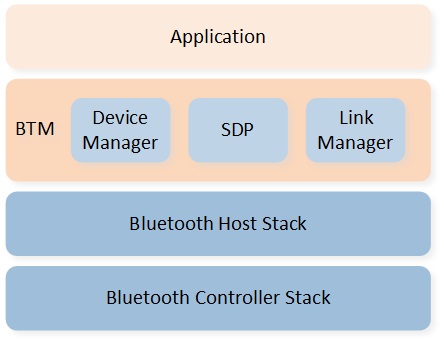
BREDR Host Architecture
As shown above, Bluetooth BR/EDR Host APIs can be divided into several modules:
Device Management APIs: It will be introduced in BR/EDR Device Management.
SDP APIs: It will be introduced in BR/EDR SDP.
BR/EDR Link Management APIs: It will be introduced in BR/EDR Link Management.
The application can interact with the BR/EDR Host through Device Management, SDP, and Link Management APIs, as well as callback messages.
Note
There is an ongoing process of restructuring the BR/EDR Host APIs. Some APIs within the application folder are being moved to more suitable locations or encapsulated.
Feature Set
The supported Bluetooth technology features in different chips are detailed in BR/EDR Host Supported Features in Supported Features. The provided functions are as below:
Device Configuration: Including functions to get/set Bluetooth device address, set local device name, set Class of Device, set/get device mode, and set security parameters.
Discovery: Including functions to add/delete SDP record, profile service discovery, device information discovery, and BR/EDR device discovery.
Link Management: Including functions to establish BR/EDR link, and configure link parameters.
Provided APIs
The BR/EDR Device Management defines the common requirements related to modes and access procedures. The Service Discovery Protocol (SDP) provides means for the application to discover which services are available and to determine the characteristics of those available services. The BR/EDR Link Management provides means for the application to establish BR/EDR link or control BR/EDR link according to different scenarios.
The table below shows a simple description of BR/EDR Host APIs.
Header File |
Description |
API Reference |
|---|---|---|
|
Establish/Control BR/EDR link, service discovery, etc. |
|
|
Set general parameters such as Class of Device, etc. |
|
|
Set BR/EDR general parameters such as supervision timeout, etc. |
Functions
BR/EDR Device Management
The BR/EDR Device Management will be introduced in the following several parts:
Bluetooth Device Address
BR/EDR Device Name
BR/EDR Class of Device
BR/EDR Device Mode
BR/EDR Device Discovery
BR/EDR Security Management
BR/EDR Device Initialization
The application shall call gap_br_set_param() and gap_set_param() to configure
BR/EDR Host parameters before stack initialization, and the application shall call gap_start_bt_stack()
to trigger stack initialization. After stack initialization, the application will receive BT_EVENT_READY event.
Bluetooth Device Address
Each Bluetooth device shall be allocated a unique 48-bit Bluetooth device address. The BD_ADDR uniquely identifies the device to another Bluetooth device. The BD_ADDR shall be a 48-bit extended unique identifier (EUI-48) created in accordance with section 8.2 (Universal addresses) of The IEEE 802-2014 Standard.
Bluetooth Device Address Configuration
The user can configure BR/EDR device address in MCUConfig Tool.
The Bluetooth device address configured in MCUConfig Tool will be set directly to stack layer. After
stack initialization, the application will receive BT_EVENT_READY
event with parameter Bluetooth device address currently used. The application shall call the API
gap_set_bd_addr() to set Bluetooth device address after stack initialization.
BR/EDR Device Name
The BR/EDR device name is the user-friendly name that a Bluetooth device exposes to remote devices.
BR/EDR Device Name Configuration
The user can configure BR/EDR device name in MCUConfig Tool.
The maximum length of BR/EDR device name is 40 bytes. The application shall call gap_br_set_param()
with parameter T_GAP_BR_PARAM_TYPE set to GAP_BR_PARAM_NAME to configure BR/EDR device
name before stack initialization. After stack initialization, the application shall call the API
bt_local_name_set() to set BR/EDR device name at runtime.
BR/EDR Device Name Reading
The application can call bt_remote_name_req() to obtain the
user-friendly name of another BR/EDR device.
As shown below, the application will receive BT_EVENT_REMOTE_NAME_RSP
event after remote name request procedure is finished.
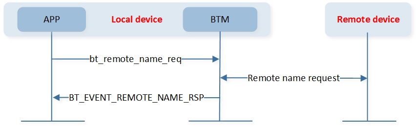
BR/EDR Remote Name Request
Note
The parameter name in BT_EVENT_REMOTE_NAME_RSP event is a null-terminated (0x00) string.
BR/EDR Class of Device
Class of Device is used to indicate the type of device. The Class of Device is composed of four fields: a Major Service Classes bitfield, a Major Device Class enumerated value, the Minor Device Classes, and a fixed value of 0b00 in the two least significant bits. The structure of the Class of Device is shown below:

BR/EDR Class of Device Structure
The format of the Minor Device Class is determined by the Major Device Class value. The Major and Minor Device Class field should not be used to determine whether a device supports any specific service(s). The terms for the defined Major Service Classes, Major Device Classes, and Minor Device Classes are defined in Bluetooth Assigned-Numbers.
The application shall call gap_br_set_param() with parameter T_GAP_BR_PARAM_TYPE
set to GAP_BR_PARAM_COD to configure Class of Device before stack initialization.
BR/EDR Device Mode
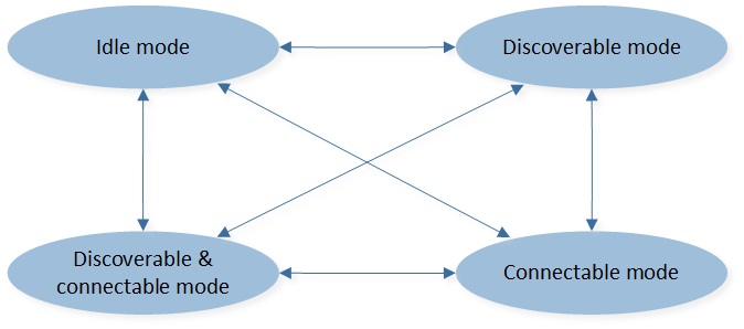
The user can change the connectivity and discoverability of the device by configuring device mode. There are four device modes:
BT_DEVICE_MODE_IDLE: Undiscoverable and Non-connectable ModeBT_DEVICE_MODE_DISCOVERABLE: Discoverable and Non-connectable ModeBT_DEVICE_MODE_CONNECTABLE: Undiscoverable and Connectable ModeBT_DEVICE_MODE_DISCOVERABLE_CONNECTABLE: Discoverable and Connectable Mode
As shown below, the four device modes can be switched unconditionally.
BR/EDR Device Mode State
BR/EDR Device Mode Configuration
The default device mode in stack is undiscoverable and non-connectable mode. The application shall call
gap_br_set_param() with parameter T_GAP_BR_PARAM_TYPE set to GAP_BR_PARAM_RADIO_MODE
to configure default device mode when initializing BR/EDR device parameters.
Note
The device mode should be set to undiscoverable and non-connectable mode before stack initialization.
After stack initialization, the application shall call bt_device_mode_set() to configure BR/EDR
device mode at runtime. And the application will receive the BT_EVENT_DEVICE_MODE_RSP event after
device mode configuration. The device mode configuration procedure is shown below:
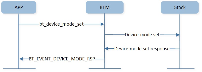
BR/EDR Device Mode Configure
As shown below, the application can trigger the next device mode configuration before receiving
the BT_EVENT_DEVICE_MODE_RSP event, as the API bt_device_mode_set() can pend the latest
device mode configuration command. And the pending device mode will be set automatically after the
last device mode configuration.
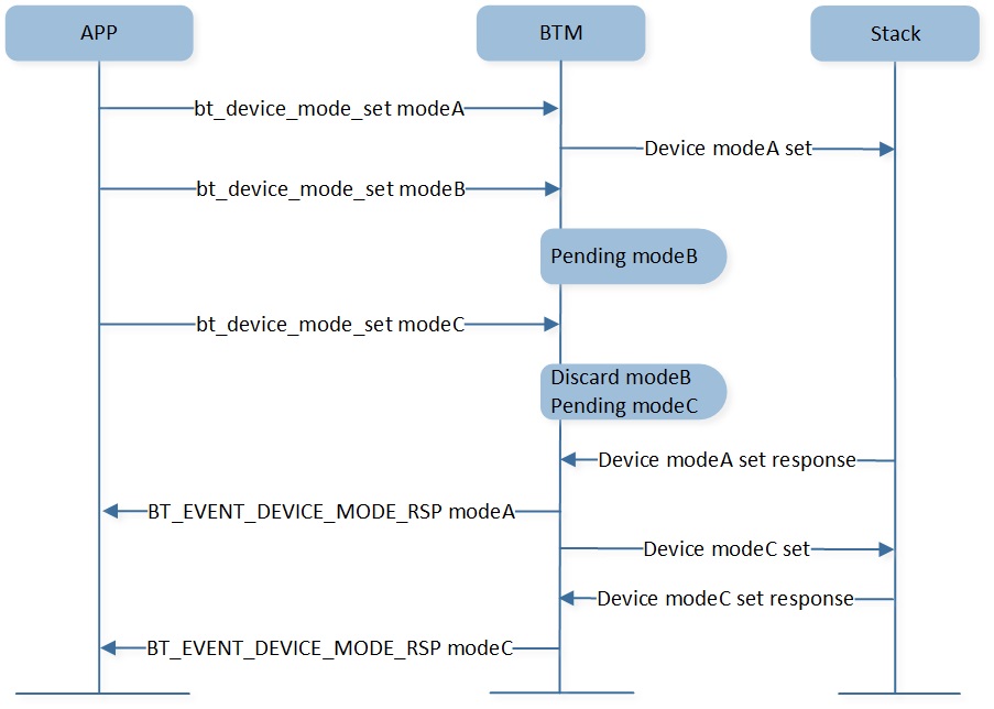
BR/EDR Device Mode Configure Continuously
The application can change the discoverable mode parameters and connectable mode parameters as required. The discoverable mode parameters include Inquiry_Scan_Type, Inquiry_Scan_Interval, and Inquiry_Scan_Window parameters.
-
Inquiry_Scan_Type
The Inquiry_Scan_Type configuration parameter indicates whether inquiry scanning will be done using non-interlaced scan or interlaced scan. If the scan interval is not at least twice the scan window then generalized interlaced scan shall not be used.
The default value is
GAP_INQUIRY_SCAN_TYPE_INTERLACED.The application can call
gap_br_set_param()with the parameterT_GAP_BR_PARAM_TYPEset toGAP_BR_PARAM_INQUIRY_SCAN_TYPEto configure the default Inquiry_Scan_Type when initializing BR/EDR device parameters. The recommended value isGAP_INQUIRY_SCAN_TYPE_INTERLACED.
-
Inquiry_Scan_Interval
The Inquiry_Scan_Interval configuration parameter defines the amount of time between consecutive inquiry scans. This is defined as the time interval from when the BR/EDR Controller started its last inquiry scan until it begins the next inquiry scan.
The Inquiry_Scan_Interval ranges from 0x0012 to 0x1000 in 625 microseconds slot unit, and only even values are valid. The default value is 0x1000.
The application can call
gap_br_set_param()with the parameterT_GAP_BR_PARAM_TYPEset toGAP_BR_PARAM_INQUIRY_SCAN_INTERVALto configure the default Inquiry_Scan_Interval when initializing BR/EDR device parameters. The recommended value is 0x1000.
-
Inquiry_Scan_Window
The Inquiry_Scan_Window configuration parameter defines the amount of time for the duration of the inquiry scan. The Inquiry_Scan_Window can only be less than or equal to the Inquiry_Scan_Interval.
The Inquiry_Scan_Window ranges from 0x0011 to Inquiry_Scan_Interval in 625 microseconds slot unit. The default value is 0x12.
The application can call
gap_br_set_param()with the parameterT_GAP_BR_PARAM_TYPEset toGAP_BR_PARAM_INQUIRY_SCAN_WINDOWto configure the default Inquiry_Scan_Window when initializing BR/EDR device parameters. The recommended value is 0x12.
The connectable mode parameters include Page_Scan_Type, Page_Scan_Interval, and Page_Scan_Window parameters.
-
Page_Scan_Type
The Page_Scan_Type parameter indicates whether page scanning will be done using non-interlaced scan or interlaced scan. If the scan interval is not at least twice the scan window, then generalized interlaced scan shall not be used.
The default value is
GAP_PAGE_SCAN_TYPE_STANDARD.The application can call
gap_br_set_param()with the parameterT_GAP_BR_PARAM_TYPEset toGAP_BR_PARAM_PAGE_SCAN_TYPEto configure the default Page_Scan_Type when initializing BR/EDR device parameters. The recommended value isGAP_PAGE_SCAN_TYPE_INTERLACED.
-
Page_Scan_Interval
The Page_Scan_Interval configuration parameter defines the amount of time between consecutive page scans. This time interval is defined from when the Controller started its last page scan until it begins the next page scan.
The Page_Scan_Interval ranges from 0x0012 to 0x1000 in 625 microseconds slot unit, and only even values are valid. The default value is 0x800.
The application can call
gap_br_set_param()with the parameterT_GAP_BR_PARAM_TYPEset toGAP_BR_PARAM_PAGE_SCAN_INTERVALto configure the default Page_Scan_Interval when initializing BR/EDR device parameters. The recommended value is 0x800.
-
Page_Scan_Window
The Page_Scan_Window configuration parameter defines the amount of time for the duration of the page scan. The Page_Scan_Window can only be less than or equal to the Page_Scan_Interval.
The Page_Scan_Window ranges from 0x0011 to Page_Scan_Interval in 625 microseconds slot unit. The default value is 0x12.
The application can call
gap_br_set_param()with the parameterT_GAP_BR_PARAM_TYPEset toGAP_BR_PARAM_PAGE_SCAN_WINDOWto configure the default Page_Scan_Window when initializing BR/EDR device parameters. The recommended value is 0x12.
-
Page_Scan_Repetition_Mode
The Page_Scan_Repetition_Mode configuration parameter indicates the interval between two consecutive page scan windows. The relationship between scan interval and page scan repetition modes is shown in the table below.
The default value is
GAP_PAGE_SCAN_REPETITION_R2.The application can call
gap_br_set_param()with parameterT_GAP_BR_PARAM_TYPEset toGAP_BR_PARAM_PAGE_SCAN_REPETITION_MODEto configure the default Page_Scan_Repetition_Mode when initializing BR/EDR device parameters. And the recommended value isGAP_PAGE_SCAN_REPETITION_R1.
Page Scan Repetition Modes |
Page Scan Interval |
|---|---|
R0 |
Less than or equal to 1.28 s and equal to page scan window. |
R1 |
Less than or equal to 1.28 s. |
R2 |
Less than or equal to 2.56 s. |
BR/EDR Device Mode Reading
After stack initialization, the application can call bt_device_mode_get() to get current device mode at runtime.
Note
The device mode obtained by bt_device_mode_get() may be meaningless quickly if there is a device mode configuration in process.
BR/EDR Device Discovery
The purpose of the BR/EDR device discovery procedure is to provide the initiator with the BR/EDR device address, Class of Device, RSSI, and extended inquiry response information of devices in discoverable mode.
BR/EDR One-Time Inquiry
As shown below, the application can call bt_inquiry_start() to start an one-time inquiry procedure.
After one-time inquiry started successfully, the application will receive BT_EVENT_INQUIRY_RSP event
with cause 0x0, otherwise, the one-time inquiry start failed. After one-time inquiry started successfully,
the application will receive a BT_EVENT_INQUIRY_RESULT event when a nearby device is found. The application
will receive BT_EVENT_INQUIRY_CMPL event after one-time inquiry command finished.
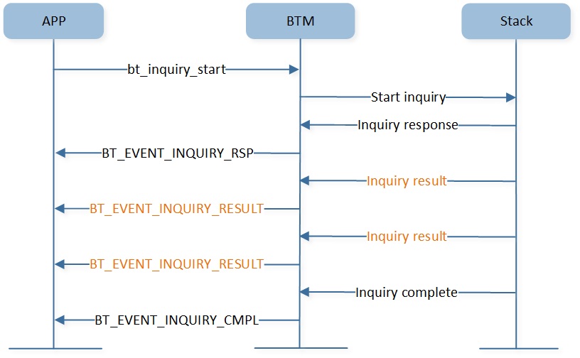
BR/EDR One Time Inquiry
As shown below, the application can stop the one-time inquiry procedure after receiving BT_EVENT_INQUIRY_RSP
event with cause 0x0. And the application will receive BT_EVENT_INQUIRY_CANCEL_RSP event after inquiry is canceled.
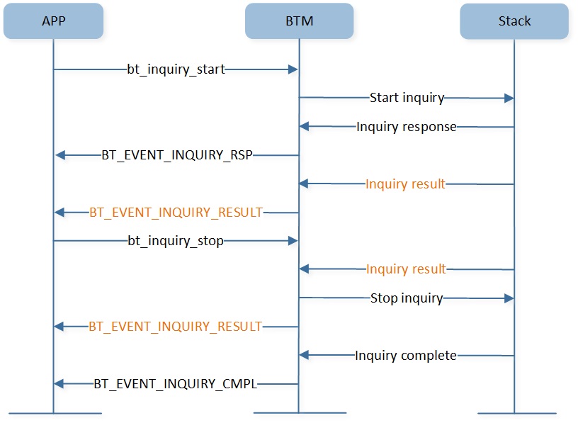
BR/EDR One Time Inquiry Cancel
As stopping one-time inquiry is an asynchronous process, the application may still receive BT_EVENT_INQUIRY_RESULT
event after calling bt_inquiry_stop() successfully.
As shown below, if the application calls bt_inquiry_stop() when one-time inquiry has
been finished and the application has not received BT_EVENT_INQUIRY_CMPL event,
the application will receive BT_EVENT_INQUIRY_CMPL event first, followed by the
BT_EVENT_INQUIRY_CANCEL_RSP event.

BR/EDR One Time Inquiry Cancel When Completed
BR/EDR Periodic Inquiry
Periodic inquiry is used when the inquiry procedure is to be repeated periodically.
As shown below, the application can call bt_periodic_inquiry_start() to start periodic inquiry.
And the application can call bt_periodic_inquiry_stop() to stop periodic inquiry.
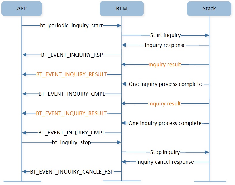
BR/EDR Periodic Inquiry
The parameters Max_Period_Length and Min_Period_Length define the time range between two consecutive
inquiries, from the beginning of an inquiry until the start of the next inquiry. The BR/EDR Controller
will use this range to determine a new random time between two consecutive inquiries for each inquiry.
When each of the inquiry processes is completed, the application will receive a BT_EVENT_INQUIRY_CMPL
event which means the latest inquiry process has finished.
Note
Max_Period_Length shall be greater than Min_Period_Length.
Min_Period_Length shall be greater than Inquiry_Length.
A device which responds during a periodic inquiry process will be reported to the application only once.
BR/EDR Security Management
The BR/EDR security model includes five distinct security features:
Pairing: The process for creating one or more shared secret keys.
Bonding: The act of storing the keys created during pairing for use in subsequent connections in order to form a trusted device pair.
Device Authentication: Verification that the two devices have the same keys.
Encryption: Message confidentiality.
Message Integrity: Protects against message forgeries.
The purpose of this chapter is to give an overview of security setting and bond information management. The application should set appropriate security parameters according to the local features to ensure pairing, authentication, and encryption work properly.
Pairing Mode
The pairing mode parameter is used to configure whether pairing with a new device is allowed.
The application can call gap_set_param() with parameter T_GAP_PARAM_TYPE
set to GAP_PARAM_BOND_PAIRING_MODE to configure pairing mode before stack initialization.
Pairing Mode Authentication Requirements
The authentication requirements are used to configure MITM and bonding flags.
To make sure the authentication procedure works properly, the application must call gap_set_param() with parameter
T_GAP_PARAM_TYPE set to GAP_PARAM_BOND_AUTHEN_REQUIREMENTS_FLAGS
to configure authentication requirements parameters before stack initialization.
IO Capabilities
The IO capabilities are used to set local input and output capabilities for device authentication.
The input capabilities are shown as below:
Capability |
Description |
|---|---|
No Input |
Device does not have the ability to indicate 'yes' or 'no'. |
Yes/No |
Device has at least two buttons that are mapped easily to 'yes' and 'no' or the device has a mechanism whereby the user can indicate either 'yes' or 'no'. |
Keyboard |
Device has a numeric keyboard that can input the numbers '0' through '9' and a confirmation. Device also has two buttons that can be easily mapped to 'yes' and 'no' or the device has a mechanism whereby the user can indicate either 'yes' or 'no'. |
The output capabilities are shown as below:
Capability |
Description |
|---|---|
No Output |
Device does not have the ability to display or communicate a 6 digit decimal number. |
Numeric Output |
Device has the ability to display or communicate a 6 digit decimal number. |
To make sure the authentication procedure works properly, the application shall call gap_set_param()
with parameter T_GAP_PARAM_TYPE set to GAP_PARAM_BOND_IO_CAPABILITIES to configure
IO capabilities parameters. The mapping of input/output capabilities to IO capabilities is shown as below:
Local Output Capability |
|||
|---|---|---|---|
No Output |
Numeric Output |
||
Local Input Capability |
No Input |
NoInputNoOutput |
DisplayOnly |
Yes/No |
NoInputNoOutput |
DisplayYesNo |
|
Keyboard |
KeyboardOnly |
DisplayYesNo |
|
As shown below, the authentication method used is deterministic based on the IO capabilities of the two devices.
Initiator |
|||||
|---|---|---|---|---|---|
DisplayOnly |
DisplayYesNo |
KeyboardOnly |
NoInputNoOutput |
||
Responder |
DisplayOnly |
Numeric Comparison |
Numeric Comparison |
Passkey Entry |
Numeric Comparison |
DisplayYesNo |
Numeric Comparison |
Numeric Comparison |
Passkey Entry |
Numeric Comparison |
|
KeyboardOnly |
Passkey Entry |
Passkey Entry |
Passkey Entry |
Numeric Comparison |
|
NoInputNoOutput |
Numeric Comparison |
Numeric Comparison |
Numeric Comparison |
Numeric Comparison |
|
The application will receive the corresponding authentication method message in the callback function
registered with bt_mgr_cback_register().
If the application receives
BT_EVENT_LINK_USER_CONFIRMATION_REQevent, it shall respond by callinggap_br_user_cfm_req_cfm(). The application can choose whether to require user confirmation based on the just_work parameter and local IO capabilities.If the application receives
BT_EVENT_LINK_USER_PASSKEY_REQevent, it shall wait for user to enter the key and callgap_br_input_passkey()to reply.If the application receives
BT_EVENT_LINK_USER_PASSKEY_NOTIFevent, it shall display the key in its UI terminal.
OOB Data
The OOB association model is primarily designed for scenarios where an Out of Band mechanism is used to both discover the devices as well as to exchange or transfer cryptographic numbers used in the pairing process.
As shown below, the contents of the OOB data block are:
-
Mandatory Contents:
Length (2 bytes)
BD_ADDR (6 bytes)
-
Optional Contents:
Class of Device (3 bytes)
Simple Pairing Hash C (16 bytes)
Simple Pairing Randomizer R (16 bytes)
Local Name (variable length)
Other Information
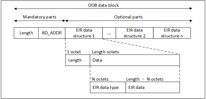
BR/EDR OOB Data Block Format
Note
The length field includes all bytes in the OOB data block including the length field itself.
The BD_ADDR will be a fixed field at the beginning of the OOB data block.
Following the BD_ADDR will be zero or more EIR tag fields containing optional contents.
The EIR tag format will be used for the optional contents.
The OOB mechanism may be implemented as either read only or read/write. If one side is read only, a one-way authentication is performed. If both sides are read/write, a two-way authentication is performed.
Each OOB transfer will have unique C and R values. After each OOB transfer, the application shall obtain
a new set of values for the next OOB transfer. The application should call gap_set_param() with the parameter T_GAP_PARAM_TYPE set to GAP_PARAM_BOND_OOB_ENABLED to configure whether OOB is supported.
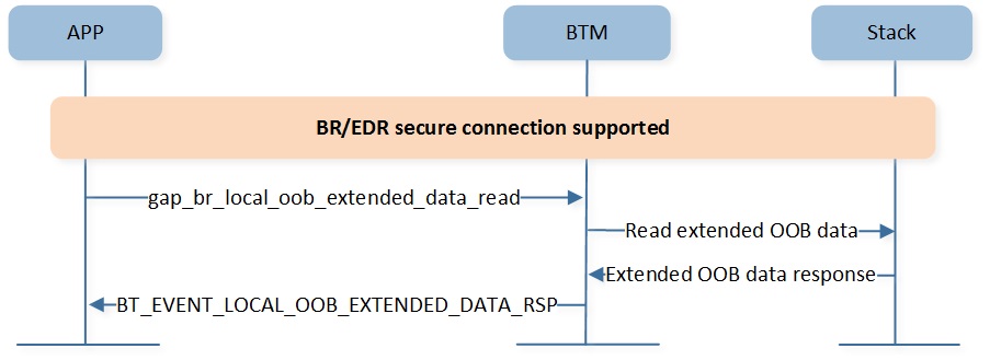
BR/EDR Read Extended OOB Data
As shown above, if OOB is supported and GAP_AUTHEN_BIT_SC_BR_FLAG has been set in authentication requirements,
the application shall call gap_br_local_oob_extended_data_read() to collect OOB data, and BT_EVENT_LOCAL_OOB_EXTENDED_DATA_RSP will be received.
As shown below, if OOB is supported and GAP_AUTHEN_BIT_SC_BR_FLAG has not been set in authentication requirements,
the application shall call gap_br_local_oob_read() to collect OOB data, and BT_EVENT_LOCAL_OOB_DATA_RSP will be received.
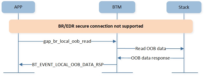
BR/EDR Read OOB Data
BR/EDR Bond Information Management
If GAP_AUTHEN_BIT_BONDING_FLAG has been set in authentication requirements, the application should manage the bond informations of paired devices. The application can manage bond informations using the implementation in the BR/EDR Host, or using functions registered with bt_bond_register_hal().
The contents of bond informations in BR/EDR Host for each bonded device are:
Maximum Bond Device Number (1 byte)
Bond Information Index (1 byte)
Bond Information Priority (1 byte)
Remote Bluetooth Device Address (6 bytes)
Link Key Type (1 byte)
Link Key (16 bytes)
Bond Flag (4 bytes)
The application can configure the stack layer maximum bond device number in MCUConfig Tool.
And the application can call bt_max_bond_num_get() to get maximum bond device number in stack layer.
The bond information index is the unique index for each bonded device's bond information. When the application
saving a new Bluetooth device's bond information, the bond information index is allocated automatically in
stack layer and cannot be changed.
The bond information priority indicates the priority of bonded device, ranging from 1 to maximum bond device number. The larger the priority value, the higher the priority.
BR/EDR Device Initialization
The purpose of this chapter is to give an overview of device initialization and startup flow which includes how to configure BR/EDR device parameters and BR/EDR device startup flow.
BR/EDR Device Parameters Initialization
Parameter initialize is performed in app_main.c by modifying the code as shown below:
static void app_bt_gap_init(void)
{
    uint32_t class_of_device = (uint32_t)((app_cfg_const.class_of_device[0]) |
                                          (app_cfg_const.class_of_device[1] << 8) |
                                          (app_cfg_const.class_of_device[2] << 16));

    uint16_t supervision_timeout = DEFAULT_SUPVISIONTIMEOUT;
    uint16_t link_policy = GAP_LINK_POLICY_ROLE_SWITCH | GAP_LINK_POLICY_SNIFF_MODE;
    uint8_t radio_mode = GAP_RADIO_MODE_NONE_DISCOVERABLE;
    bool limited_discoverable = false;
    bool auto_accept_acl = false;

    uint8_t  pagescan_type = GAP_PAGE_SCAN_TYPE_INTERLACED;
    uint16_t pagescan_interval = DEFAULT_PAGESCAN_INTERVAL;
    uint16_t pagescan_window = DEFAULT_PAGESCAN_WINDOW;
    uint16_t page_timeout = DEFAULT_PAGE_TIMEOUT;
    uint8_t  page_scan_repetition_mode = GAP_PAGE_SCAN_REPETITION_R1;

    uint8_t inquiryscan_type = GAP_INQUIRY_SCAN_TYPE_INTERLACED;
    uint16_t inquiryscan_window = DEFAULT_INQUIRYSCAN_WINDOW;
    uint16_t inquiryscan_interval = DEFAULT_INQUIRYSCAN_INTERVAL;
    uint8_t inquiry_mode = GAP_INQUIRY_MODE_EXTENDED_RESULT;

    uint8_t pair_mode = GAP_PAIRING_MODE_PAIRABLE;
    uint16_t auth_flags = GAP_AUTHEN_BIT_BONDING_FLAG | GAP_AUTHEN_BIT_SC_FLAG;
    uint8_t io_cap = GAP_IO_CAP_NO_INPUT_NO_OUTPUT;
    uint8_t oob_enable = false;
    uint8_t bt_mode = GAP_BT_MODE_21ENABLED;

    bt_bond_init();

    gap_lib_init();

    //0: to be master
    gap_br_cfg_accept_role(1);

    gap_br_set_param(GAP_BR_PARAM_NAME, GAP_DEVICE_NAME_LEN, app_cfg_nv.device_name_legacy);

    gap_set_param(GAP_PARAM_BOND_PAIRING_MODE, sizeof(uint8_t), &pair_mode);
    gap_set_param(GAP_PARAM_BOND_AUTHEN_REQUIREMENTS_FLAGS, sizeof(uint16_t), &auth_flags);
    gap_set_param(GAP_PARAM_BOND_IO_CAPABILITIES, sizeof(uint8_t), &io_cap);
    gap_set_param(GAP_PARAM_BOND_OOB_ENABLED, sizeof(uint8_t), &oob_enable);

    gap_br_set_param(GAP_BR_PARAM_BT_MODE, sizeof(uint8_t), &bt_mode);
    gap_br_set_param(GAP_BR_PARAM_COD, sizeof(uint32_t), &class_of_device);
    gap_br_set_param(GAP_BR_PARAM_LINK_POLICY, sizeof(uint16_t), &link_policy);
    gap_br_set_param(GAP_BR_PARAM_SUPV_TOUT, sizeof(uint16_t), &supervision_timeout);
    gap_br_set_param(GAP_BR_PARAM_AUTO_ACCEPT_ACL, sizeof(bool), &auto_accept_acl);

    gap_br_set_param(GAP_BR_PARAM_RADIO_MODE, sizeof(uint8_t), &radio_mode);
    gap_br_set_param(GAP_BR_PARAM_LIMIT_DISCOV, sizeof(bool), &limited_discoverable);

    gap_br_set_param(GAP_BR_PARAM_PAGE_SCAN_TYPE, sizeof(uint8_t), &pagescan_type);
    gap_br_set_param(GAP_BR_PARAM_PAGE_SCAN_INTERVAL, sizeof(uint16_t), &pagescan_interval);
    gap_br_set_param(GAP_BR_PARAM_PAGE_SCAN_WINDOW, sizeof(uint16_t), &pagescan_window);
    gap_br_set_param(GAP_BR_PARAM_PAGE_TIMEOUT, sizeof(uint16_t), &page_timeout);
    gap_br_set_param(GAP_BR_PARAM_PAGE_SCAN_REPETITION_MODE, sizeof(uint8_t), &page_scan_repetition_mode);

    gap_br_set_param(GAP_BR_PARAM_INQUIRY_SCAN_TYPE, sizeof(uint8_t), &inquiryscan_type);
    gap_br_set_param(GAP_BR_PARAM_INQUIRY_SCAN_INTERVAL, sizeof(uint16_t), &inquiryscan_interval);
    gap_br_set_param(GAP_BR_PARAM_INQUIRY_SCAN_WINDOW, sizeof(uint16_t), &inquiryscan_window);
    gap_br_set_param(GAP_BR_PARAM_INQUIRY_MODE, sizeof(uint8_t), &inquiry_mode);
}
BR/EDR Device Startup Flow
The application should configure BR/EDR device parameters firstly, and call gap_start_bt_stack() in application task.
The application can call bt_mgr_cback_register() to receive callback messages. And the application will receive BT_EVENT_READY after BR/EDR device initialization.
static void app_device_bt_cback(T_BT_EVENT event_type, void *event_buf, uint16_t buf_len)
{
    T_BT_EVENT_PARAM *param = event_buf;
    bool handle = true;

    switch (event_type)
    {
    case BT_EVENT_READY:
        {
            //do something after stack initializing completely
        }
        break;

    default:
        break;
    }
}

int main(void)
{
    ......
    app_bt_gap_init();
    ......
    bt_mgr_init();
    ......
    bt_mgr_cback_register(app_bt_cback);
}

void app_main_task(void *p_param)
{
    ......
    gap_start_bt_stack(evt_queue_handle, io_queue_handle, MAX_NUMBER_OF_GAP_MESSAGE);
    ......
}
BR/EDR SDP
The SDP layer will be introduced according to the following several parts:
BR/EDR SDP Capacity
BR/EDR SDP Data Representation
BR/EDR SDP Initialization
BR/EDR SDP Capacity
The service discovery mechanism provides the means for client applications to discover the existence of services provided by server applications as well as the attributes of those services. The attributes of a service include the type or class of service offered and the mechanism or protocol information needed to utilize the service.
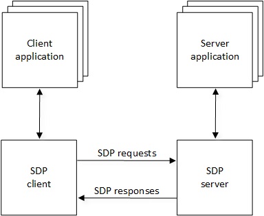
BR/EDR SDP Client Server Interaction
As shown above, SDP involves communication between a SDP server and a SDP client.
The server maintains a SDP database which consists of a list of service records that describe the characteristics of services associated with the server. Each service record contains information about a single service.
A client can retrieve information from a service record maintained by the SDP server by issuing a SDP request.
BR/EDR Device Identification Discovery
Device ID information for the device is exported in terms of an explicit SDP record on that device. The Device ID Service Record attributes are listed below:
Attribute |
Attribute ID |
Attribute Value Type |
|---|---|---|
SpecificationID |
0x0200 |
2 byte unsigned integer. |
VendorID |
0x0201 |
2 byte unsigned integer. |
ProductID |
0x0202 |
2 byte unsigned integer. |
Version |
0x0203 |
2 byte unsigned integer. |
PrimaryRecord |
0x0204 |
Boolean. |
VendorIDSource |
0x0205 |
2 byte unsigned integer. |
-
SpecificationID
The SpecificationID is intended to reflect the version number of the Bluetooth Device ID Profile specification supported by the device.
The two most significant hexadecimal digits will indicate the major number of the Bluetooth Device ID Profile specification, and the two least significant hexadecimal digits will reflect the minor number of the specification. For example, version 1.3 will be 0x0103.
-
VendorID
The VendorID is intended to uniquely identify the vendor of the device, which determines which organization assigned the VendorID value. The VendorID 0xFFFF is reserved as the default VendorID when no Device ID Service Record is present in the device.
-
ProductID
The ProductID is intended to distinguish between different products made by the vendor above. These IDs are managed by the vendors themselves.
-
Version
This is a vendor-assigned field, which defines the version of the product identified by the VendorID and ProductID attributes. This attribute is intended to differentiate between versions of products with identical VendorIDs and ProductIDs.
The value of the field is 0xJJMN for version JJ.M.N (JJ - major version number, M - minor version number, N - sub-minor version number).
-
PrimaryRecord
This is intended to designate one particular Device ID Service Record (in case multiple Device ID Service Records exist on a device) as the primary Device ID Service Record for the device, the PrimaryRecord attribute is set to 'true' for that record and 'false' for all other records.
The client device can use the primary Device ID Service Record from the source device for UI purposes.
-
VendorIDSource
This attribute designates which organization assigned the VendorID attribute. The defined values are shown in the table below:
Values |
Description |
|---|---|
0x0001 |
Bluetooth SIG assigned Device ID Vendor ID value from the Assigned Numbers document. |
0x0002 |
USB Implementer's Forum assigned Vendor ID value. |
0x0000, 0x0003 - 0xFFFF |
Reserved for future use. |
As shown below, the application can call bt_did_discov_start() to start a DID discover procedure.
The application will receive the BT_EVENT_DID_ATTR_INFO event with DID attributes information.
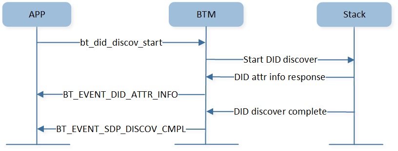
BR/EDR DID Discover
After the DID procedure is complete, the application will receive the BT_EVENT_SDP_DISCOV_CMPL event.
As shown below, the application can call bt_sdp_discov_stop() to stop a DID discover procedure.
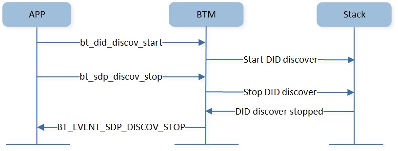
BR/EDR DID Discovery Terminate
The application will receive the BT_EVENT_SDP_DISCOV_STOP event after the DID discover procedure stopped.
BR/EDR Profile Service Discovery
For the SDP record contents of BR/EDR profiles, please refer to each profile user manual.
As shown below, the application can call bt_sdp_discov_start() to start a profile service discovery procedure. The application will receive BT_EVENT_SDP_ATTR_INFO event with profile service attributes information, after the discovery procedure is complete, the application will receive BT_EVENT_SDP_DISCOV_CMPL event.
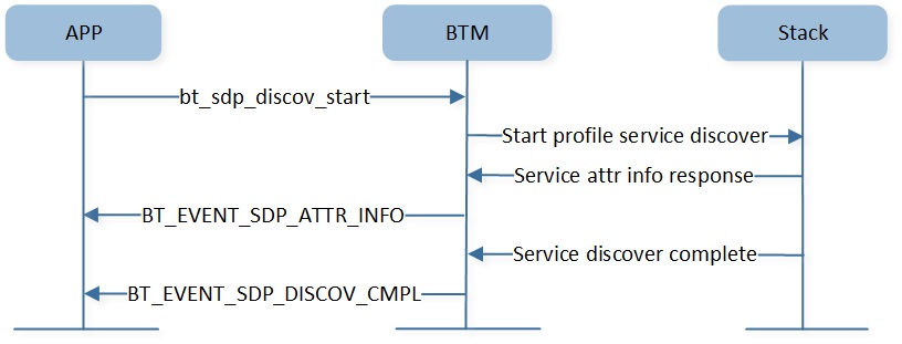
BR/EDR Profile Service Discover
As shown below, the application can call bt_sdp_discov_stop() to stop a profile service
discovery procedure. And the application will receive BT_EVENT_SDP_DISCOV_STOP event after the profile
service discovery procedure is stopped.

BR/EDR Profile Service Discover Terminate
BR/EDR SDP Data Representation
All of the information about a service that is maintained by a SDP server is contained within a single service record.
As shown below, the service record shall only be a list of service attributes.
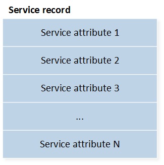
BR/EDR Service Record
The service attribute consists of two components: an attribute ID and an attribute value.
Attribute ID
An attribute ID is a 16-bit unsigned integer that distinguishes each service attribute from other service attributes within a service record. An attribute ID is represented as a data element.
Attribute Value
The attribute value is a variable length field whose meaning is determined by the attribute ID associated with it and by the service class of the service record in which the attribute is contained. An attribute value is represented as a data element.
Data Element
A data element is a typed data representation. It consists of two fields: a header field and a data field.
The header field, in turn, is composed of two parts: a type descriptor and a size descriptor.
The data is a sequence of bytes whose length is specified in the size descriptor and whose meaning is (partially) specified by the type descriptor.
Type Descriptor Value |
Valid Size Descriptor Values |
Type Description |
|---|---|---|
0 |
0 |
Nil, the null type. |
1 |
0,1,2,3,4 |
Unsigned integer. |
2 |
0,1,2,3,4 |
Signed twos-complement integer. |
3 |
1,2,4 |
UUID, a universally unique identifier. |
4 |
5,6,7 |
Text string. |
5 |
0 |
Boolean. |
6 |
5,6,7 |
Data element sequence, a data element whose data field is a sequence of data elements. |
7 |
5,6,7 |
Data element alternative, data element whose data field is a sequence of data elements from which one data element is to be selected. |
8 |
5,6,7 |
URL, a uniform resource locator. |
Other |
Reserved for future use. |
A data element type is represented as a 5-bit type descriptor. The type descriptor is contained in the most significant (high-order) 5 bits of the first byte of the data element header. As shown above, describes the definitions of data element type descriptors.
The data element size descriptor is represented as a 3-bit size index followed by 0, 8, 16, or 32 bits. The size index is contained in the least significant (low-order) 3 bits of the first byte of the data element header. As shown below, the size index is encoded as follows.
Size Index |
Additional Bits |
Data Size |
|---|---|---|
0 |
0 |
1 byte. Exception: if the data element type is nil, the data size is 0 bytes. |
1 |
0 |
2 bytes. |
2 |
0 |
4 bytes. |
3 |
0 |
8 bytes. |
4 |
0 |
16 bytes. |
5 |
8 |
The data size is contained in the additional 8 bits, which are interpreted as an unsigned integer. |
6 |
16 |
The data size is contained in the additional 16 bits, which are interpreted as an unsigned integer. |
7 |
32 |
The data size is contained in the additional 32 bits, which are interpreted as an unsigned integer. |
static const uint8_t a2dp_sdp_record[] =
{
    SDP_DATA_ELEM_SEQ_HDR,
    0x39,//0x55,
    //attribute SDP_ATTR_SRV_CLASS_ID_LIST
    SDP_UNSIGNED_TWO_BYTE,
    (uint8_t)(SDP_ATTR_SRV_CLASS_ID_LIST >> 8),
    (uint8_t)SDP_ATTR_SRV_CLASS_ID_LIST,
    SDP_DATA_ELEM_SEQ_HDR,
    0x03,
    SDP_UUID16_HDR,
    (uint8_t)(UUID_AUDIO_SINK >> 8),
    (uint8_t)(UUID_AUDIO_SINK),

    //attribute SDP_ATTR_PROTO_DESC_LIST
    SDP_UNSIGNED_TWO_BYTE,
    (uint8_t)(SDP_ATTR_PROTO_DESC_LIST >> 8),
    (uint8_t)SDP_ATTR_PROTO_DESC_LIST,
    SDP_DATA_ELEM_SEQ_HDR,
    0x10,
    SDP_DATA_ELEM_SEQ_HDR,
    0x06,
    SDP_UUID16_HDR,
    (uint8_t)(UUID_L2CAP >> 8),
    (uint8_t)(UUID_L2CAP),
    SDP_UNSIGNED_TWO_BYTE,
    (uint8_t)(PSM_AVDTP >> 8),
    (uint8_t)(PSM_AVDTP),
    SDP_DATA_ELEM_SEQ_HDR,
    0x06,
    SDP_UUID16_HDR,
    (uint8_t)(UUID_AVDTP >> 8),
    (uint8_t)(UUID_AVDTP),
    SDP_UNSIGNED_TWO_BYTE,
    0x01,
    0x03,

    //attribute SDP_ATTR_BROWSE_GROUP_LIST
    SDP_UNSIGNED_TWO_BYTE,
    (uint8_t)(SDP_ATTR_BROWSE_GROUP_LIST >> 8),
    (uint8_t)SDP_ATTR_BROWSE_GROUP_LIST,
    SDP_DATA_ELEM_SEQ_HDR,
    0x03,
    SDP_UUID16_HDR,
    (uint8_t)(UUID_PUBLIC_BROWSE_GROUP >> 8),
    (uint8_t)(UUID_PUBLIC_BROWSE_GROUP),

    //attribute SDP_ATTR_PROFILE_DESC_LIST
    SDP_UNSIGNED_TWO_BYTE,
    (uint8_t)(SDP_ATTR_PROFILE_DESC_LIST >> 8),
    (uint8_t)SDP_ATTR_PROFILE_DESC_LIST,
    SDP_DATA_ELEM_SEQ_HDR,
    0x08,
    SDP_DATA_ELEM_SEQ_HDR,
    0x06,
    SDP_UUID16_HDR,
    (uint8_t)(UUID_ADVANCED_AUDIO_DISTRIBUTION >> 8),
    (uint8_t)(UUID_ADVANCED_AUDIO_DISTRIBUTION),
    SDP_UNSIGNED_TWO_BYTE,
    0x01,//version 1.4
    0x04,

    //attribute SDP_ATTR_SUPPORTED_FEATURES
    SDP_UNSIGNED_TWO_BYTE,
    (uint8_t)(SDP_ATTR_SUPPORTED_FEATURES >> 8),
    (uint8_t)SDP_ATTR_SUPPORTED_FEATURES,
    SDP_UNSIGNED_TWO_BYTE,
    0x00,
    0x03
};
BR/EDR SDP Initialization
The SDP table will be initialized after the application calls bt_mgr_init(), and the application should add or delete SDP record after this step.
int main(void)
{
    ......
    bt_mgr_init();
    ......
    bt_sdp_record_add((void *)sdp_record);
}
As shown below, the application can call bt_sdp_record_add() to add SDP record so that the
remote device can find this service through the SDP search process.
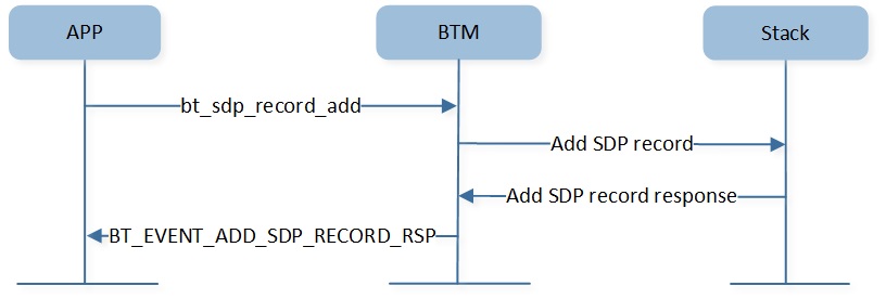
BR/EDR Add Service Record
As shown below, the application can call bt_sdp_record_delete() to delete the SDP record.
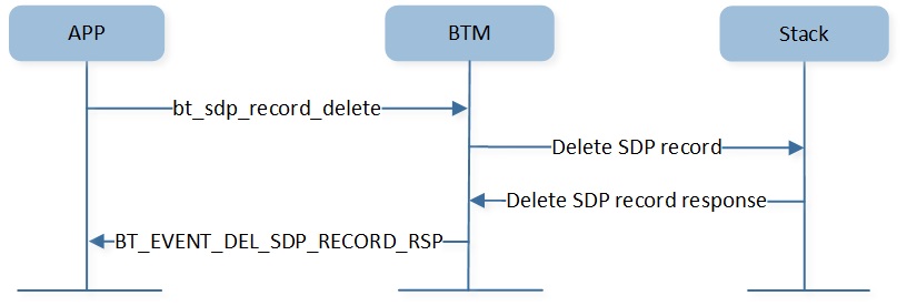
BR/EDR Delete Service Record
BR/EDR Link Management
The BR/EDR Link Management will be introduced according to the following several parts:
BR/EDR Link Establishment
BR/EDR Link Control
BR/EDR Link Establishment
The purpose of the link establishment procedure is to establish a logical transport (of ACL type) between two Bluetooth devices.
Link Creation
As shown below, the application can create an ACL link by initiating a SDP discovery process. And stack layer will check whether ACL link existed, if not, link creation process initiated automatically.
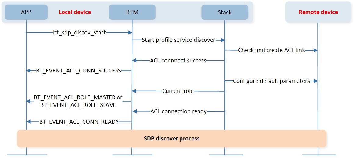
BR/EDR Link Creation
After the ACL is established, the application will receive BT_EVENT_ACL_CONN_SUCCESS event. And then after the stack layer sets default link parameters, the application receives the BT_EVENT_ACL_CONN_READY event, which means link ready.
If ACL link created failed, the application will receive BT_EVENT_ACL_CONN_FAIL event and BT_EVENT_SDP_DISCOV_CMPL event.
The default link role for link initiator is master, and the application will receive BT_EVENT_ACL_ROLE_MASTER event before link ready.
If remote device changes link role, the application will receive BT_EVENT_ACL_ROLE_SLAVE event instead of BT_EVENT_ACL_ROLE_MASTER event before link ready.
If no service channel is available for 4 seconds, the BR/EDR link will be disconnected automatically, so the application should initiate profile connection in 4 seconds after SDP discovery process completed.
Link Authentication and Encryption
The application can initiate a BR/EDR profile connection process after link ready. The stack layer will check profile security and trigger authentication and encryption process automatically. As shown below, the pairing process will be triggered if the application has no link key.
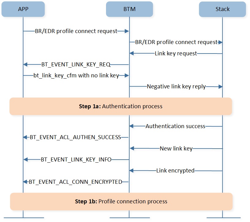
BR/EDR Link Pairing
The authentication and encryption process when the application has link key is shown as below:
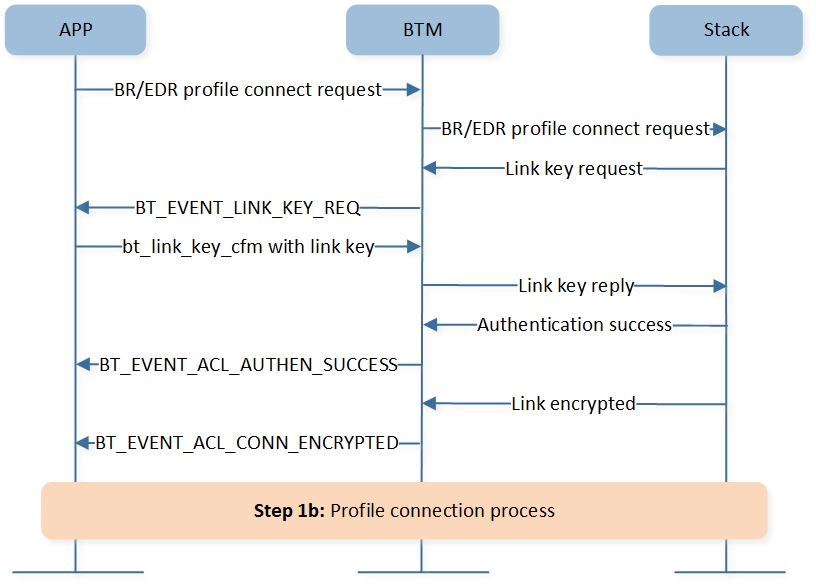
BR/EDR Link Authentication Encryption
BR/EDR Link Control
The application can change link parameters for different scenarios.
Role Switch
As shown below, the application can trigger role switch process after link ready.
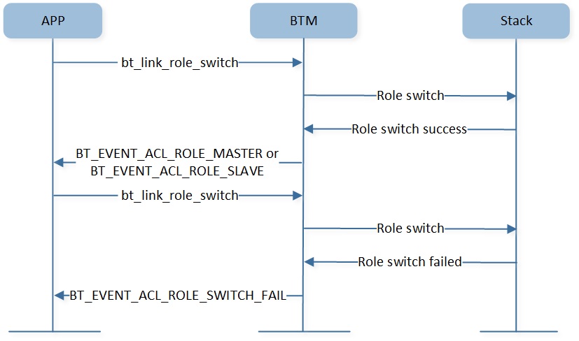
BR/EDR Link Role Switch
If the role switch process succeeds, the application will receive
BT_EVENT_ACL_ROLE_MASTERorBT_EVENT_ACL_ROLE_SLAVEevent.If the role switch process failed, the application will receive
BT_EVENT_ACL_ROLE_SWITCH_FAILevent.
As the role switch process conflicted with authentication and encryption, the application shouldn't trigger role switch when authentication or encryption is in process.
QoS Configuration
As shown below, the application can call bt_link_qos_set() to configure link QoS.
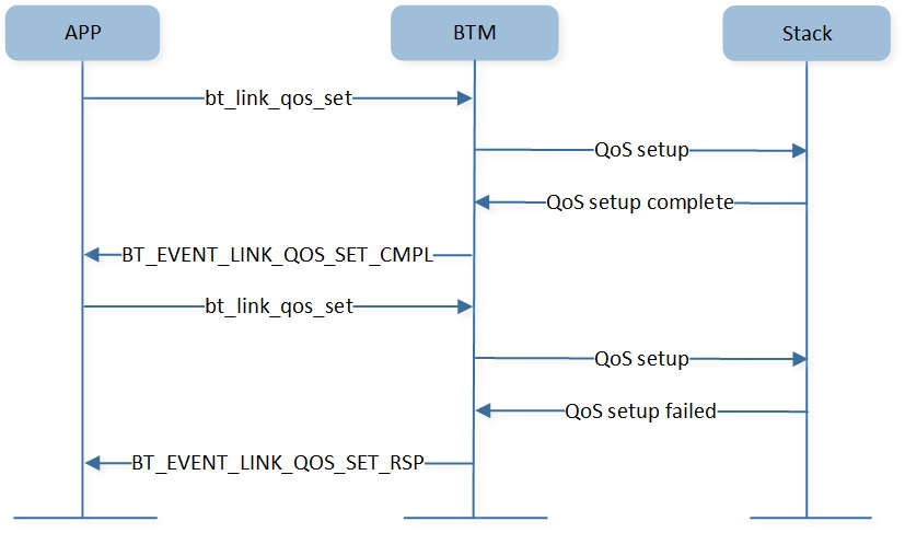
BR/EDR Link Configure QoS
If the QoS configuration process succeeds, the application will receive BT_EVENT_LINK_QOS_SET_CMPL event,
otherwise, the application will receive BT_EVENT_LINK_QOS_SET_RSP event.
Packet Type Configuration
As shown below, the application can configure using specific packet types for link communication.
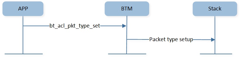
BR/EDR Link Configure Packet Type
BR/EDR Link Sniff Mode Configuration
If sniff mode is enabled, the Bluetooth manager module can automatically enter or exit sniff mode in different scenarios.
As shown below, the application can call bt_sniff_mode_enable() to enable BR/EDR link sniff
mode or change sniff mode parameters.
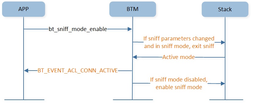
BR/EDR Link Enable Sniff Mode
As shown below, the application can call bt_sniff_mode_disable() to disable BR/EDR link sniff mode.

BR/EDR Link Disable Sniff Mode