Quick Start
This document aims to guide users in quickly setting up their development environment, which includes building the APP, downloading/updating firmware, and capturing logs. Users can download the prebuilt images included in the SDK to confirm the compatibility and functionality of the EVB and the development environment.
Overview
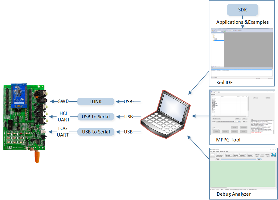
Users can build the projects in the SDK using Keil/GCC, and then use MPPG Tool to download the files onto the EVB. Once the downloading is complete, users can use Debug Analyzer to capture logs from the SoC end, as shown in the following figure.
Environment Setup
Required EVB
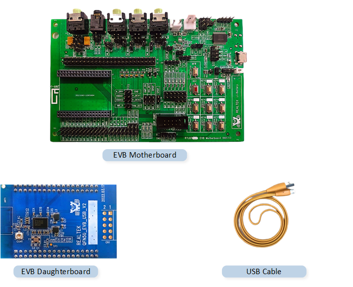
The EVB provides a hardware environment for user development and application debugging. It consists of a motherboard and a daughterboard. Please see the EVB Interfaces and Modules section for details on peripheral interface wiring.
For more information, please refer to the respective Evaluation Board User Guide available on the Realtek official website:
For RTL87x3E series, please visit https://www.realmcu.com/en/Resources/sdk/RTL8763E-Series.
For RTL87x3D series, please visit https://www.realmcu.com/en/Resources/sdk/RTL8773D-Series.
For RTL87x3EP series, please visit https://www.realmcu.com/en/Resources/sdk/RTL8773E-Series.
Note
To purchase EVB, please visit https://www.realmcu.com/en/Home/Shop.
Hardware Environment Setup
Required Files
For each RTL87x3 project, users typically need to download multiple images, including the base images and the application image. The base images contain the necessary firmware and configuration settings for the RTL87x3 chipsets, while the application image contains the specific code and functionality for the target application.
The default files for RTL87x3 are as shown in the following table. For more information about these files, please refer to Building and Downloading.
Files |
Provided by Realtek |
File Type |
Note |
|---|---|---|---|
OTA Header Image |
(MPPG Tool Generation) |
Base Image |
|
Boot Patch Image |
√ |
Base Image |
|
DSP APP Image |
√ |
Base Image |
|
DSP SYS Image |
√ |
Base Image |
|
DSP Configuration Image |
(DSPConfig Tool Generation) |
Base Image |
|
FSBL Image |
√ |
Base Image |
|
Bluetooth Controller EXT Image |
√ |
Base Image |
RTL87x3E/RTL87x3EP Only |
Platform EXT Image |
√ |
Base Image |
RTL87x3E/RTL87x3EP Only |
Stack Patch Image |
√ |
Base Image |
|
SYS Patch Image |
√ |
Base Image |
RTL87x3E/RTL87x3EP Only |
Bluetooth Host Image |
√ |
Base Image |
RTL87x3E/RTL87x3EP Only |
Patch Image |
√ |
Base Image |
RTL87x3D Only |
APP Configuration Image |
(MCUConfig Tool Generation) |
Base Image |
|
System Configuration Image |
(MCUConfig Tool Generation) |
Base Image |
|
VPData Configuration Image |
(MCUConfig Tool Generation) |
Base Image |
RTL87x3E/RTL87x3EP Only |
User Data Image |
(GUI Package Tool Generation) |
Base Image |
16M Flash Only |
APP Demo Image |
(Project Building Generation) |
Application Image |
Tools
During the development based on RTL87x3 SDK, users need to utilize Realtek's Development Toolkit and ARM/GCC Development Suite.
Tools |
Tool Version |
OS |
|
|---|---|---|---|
ARM Keil MDK |
μVision: V5.36 ARMCC: V5.06 update 6 (build 750) |
Win10 |
|
GNU Toolchain |
13.2.Rel1 or Later |
Windows/Linux |
|
MinGW |
V3.82.90 or Later |
Windows |
|
Git Bash |
Win10 |
||
J-Link Software |
V6.32 or Later |
Win10 |
|
MPPG Tool (RTK Tool) |
|
Win10 |
|
Debug Analyzer (RTK Tool) |
|
Win10 |
|
|
Win10 |
Note
All installation packages under the path are in
.zipformat and need to be manually extracted by the user.The tools are compatible for use in Windows systems.
ACI Host CLI Tool is only available in Realtek Bluetooth Common SDK.
ARM Keil MDK
Users can build all the applications in the SDK using the Keil MDK. For more detailed information, please refer to Keil MDK in the documentation.
GNU Toolchain
Users can compile applications in the SDK using the GNU Toolchain. Before development, please install gcc-arm-none-eabi. For more information, please refer to GCC section.
MinGW
Users can use MinGW to parse the Makefile.
Git Bash
As bash.exe will be used in the Before Build or After Build command line, please install Git from https://git-scm.com/downloads.
After Git is installed, take the installation in C:\Program Files as an example, and confirm that the Windows OS environment variable PATH is added with C:\Program Files\Git\bin
and C:\Program Files\Git\cmd.
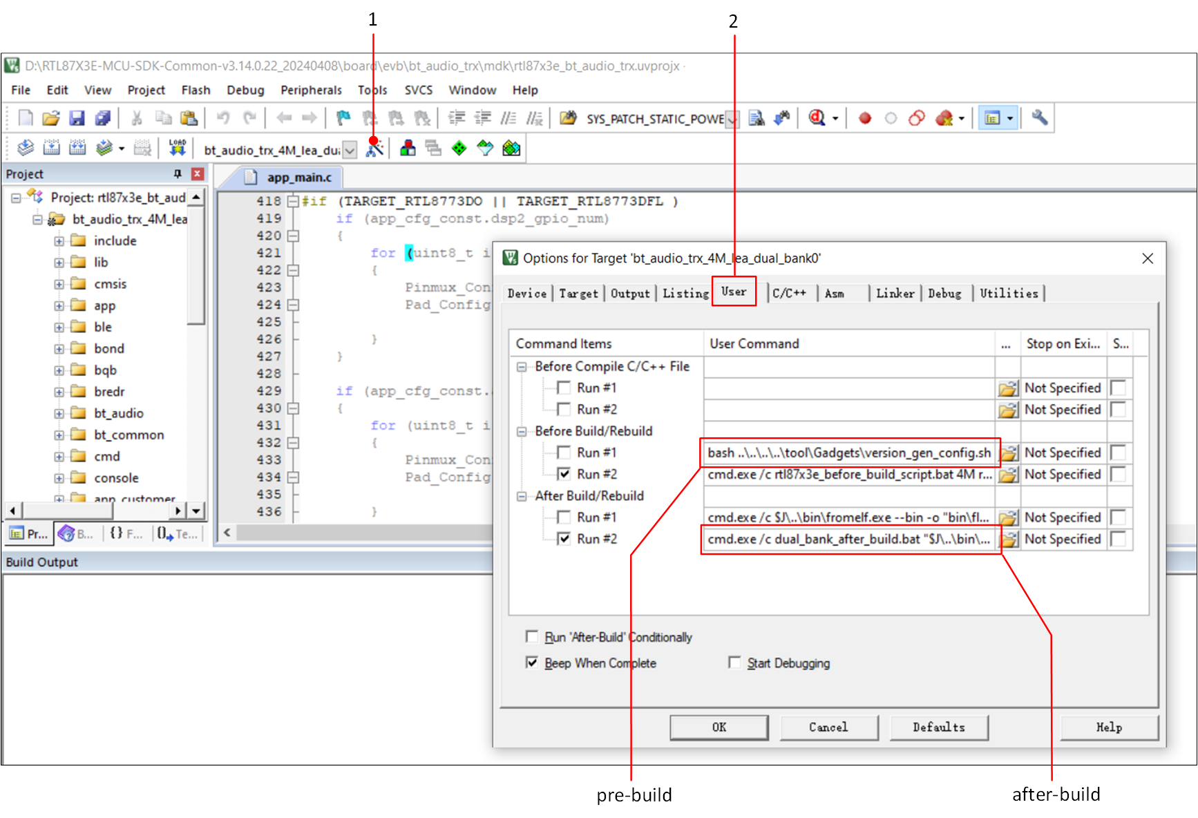
Before Build
After Build
J-Link
J-Link is another prerequisite if a more comprehensive debugging method is desired besides the logging mechanism. To install the SEGGER J-Link software, visit https://www.segger.com/ to download related software and documentation. The driver should be correctly installed for the device to use the J-Link debugger with Keil MDK.
MPPG Tool
Users can download files using MPPG Tool, which has two downloading modes: MP mode and Debug mode. MP mode is suitable for mass production. This document primarily focuses on the Debug mode, which is intended for developers in the early stages of software development. For more information, please refer to MPPG Tool.
Debug Analyzer
Users can use Debug Analyzer to capture and parse SoC logs. For more information, please refer to Debug Analyzer.
ACI Host CLI Tool
ACI Host CLI is a test tool running on PC, which is used to demo ACI usage. It can perform CMD/event communication test with ACI Device through USB serial port. For more information, please refer to ACI Host CLI Tool.
Bring Up EVB
To ensure that the EVB can work properly, users can follow the steps below:
Prepare an EVB and ensure that the EVB interface is wired correctly (refer to EVB Interfaces and Modules). Set the EVB to Download Mode (refer to Download Mode) and then power on the EVB (refer to Power Supply).
-
Double-click to run
MPPGTool.exe, as shown in the following figure. For specific operation steps and file paths, refer to MPPG Tool Download.Click Chip Erase to erase the chip before downloading.
In Flash Map, click the open folder icon to load the
flash_map.inifile.Click Add File(s) to load all the files, refer to Required Files.
Click Detect to identify the COM port of the EVB.
Click Open to open the COM port.
Click Download to start the downloading process.
-
The progress bar shows the current downloading progress and displays Success when the files are successfully downloaded.
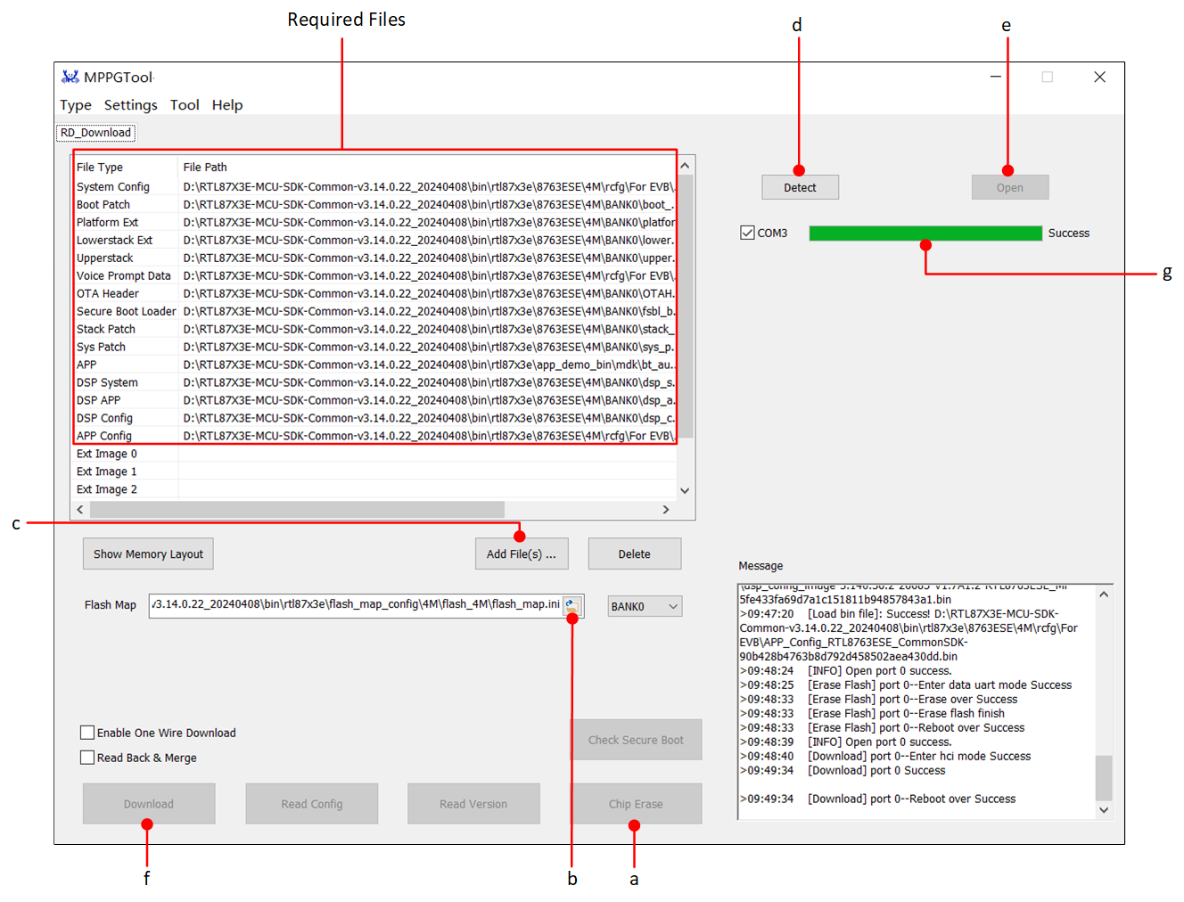
MPPG Tool Interface
After the files are downloaded completely, refer to Steps 12-13 in MPPG Tool to perform a Factory Reset.
Put the EVB into Normal Mode (refer to Normal Mode).
Observe the behavior of the EVB (LED blinking/phone searching for Bluetooth Low Energy advertising, etc., based on the actual functionality of the user's APP Image), or check whether the SoC-side log meets the expectations (refer to Example Verification).
Hardware Development Environment
The EVB provides a hardware environment for user development and application debugging. It consists of a motherboard and a daughterboard. It has Download Mode and Normal Mode, and users need to use different wiring methods to set the EVB to enter the required mode.
EVB Interfaces and Modules
Taking RTL87x3E EVB as an example, the EVB interfaces and modules are shown in the following figures.
Note
There may be some differences in the EVB wire map for different RTL87x3 ICs. For detailed information, please refer to the respective Evaluation Board User Guide.
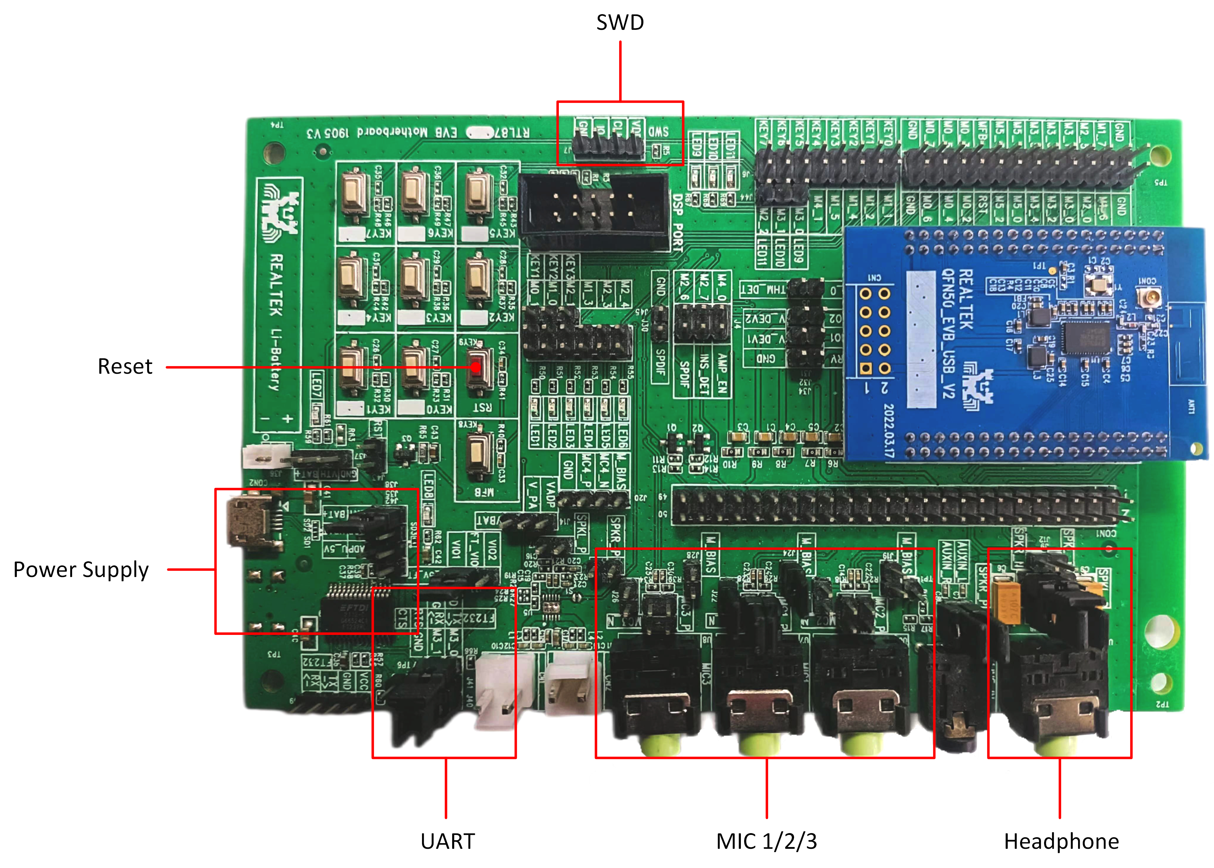
EVB Modules Distribution
Power Supply
There are two power supply modes for the EVB: USB connector and Li-ion battery.
If the EVB is powered by the USB connector, please follow the steps below:
Connect VBAT of jumper J38 to U_5V_FT (TP25).
Connect the AC adaptor to the micro-USB connector CON3, located on the opposite side of the board.
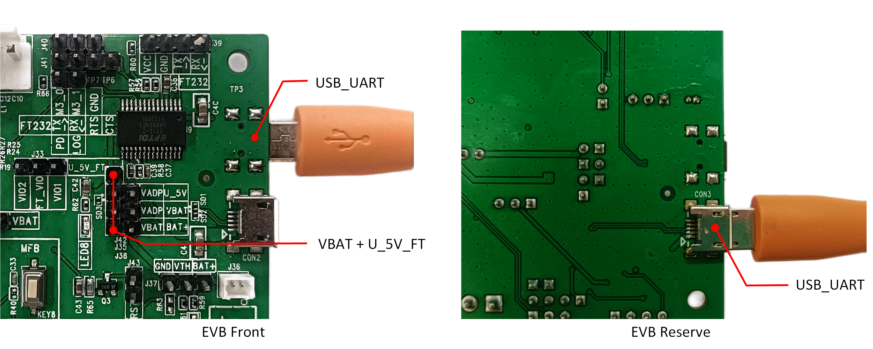
USB Power
Note
FT_5V power supply to VBAT is only for ease of operation during development and debugging with the EVB. During mass production, VBAT should not be supplied with more than 4.35V, as there is a risk of backflow voltage to the ADPIN.
If the EVB is powered by the Li-ion battery, please follow the steps below:
Short jumper J38 (VBAT and BAT+).
Connect the Li-ion battery to the BAT socket J36.
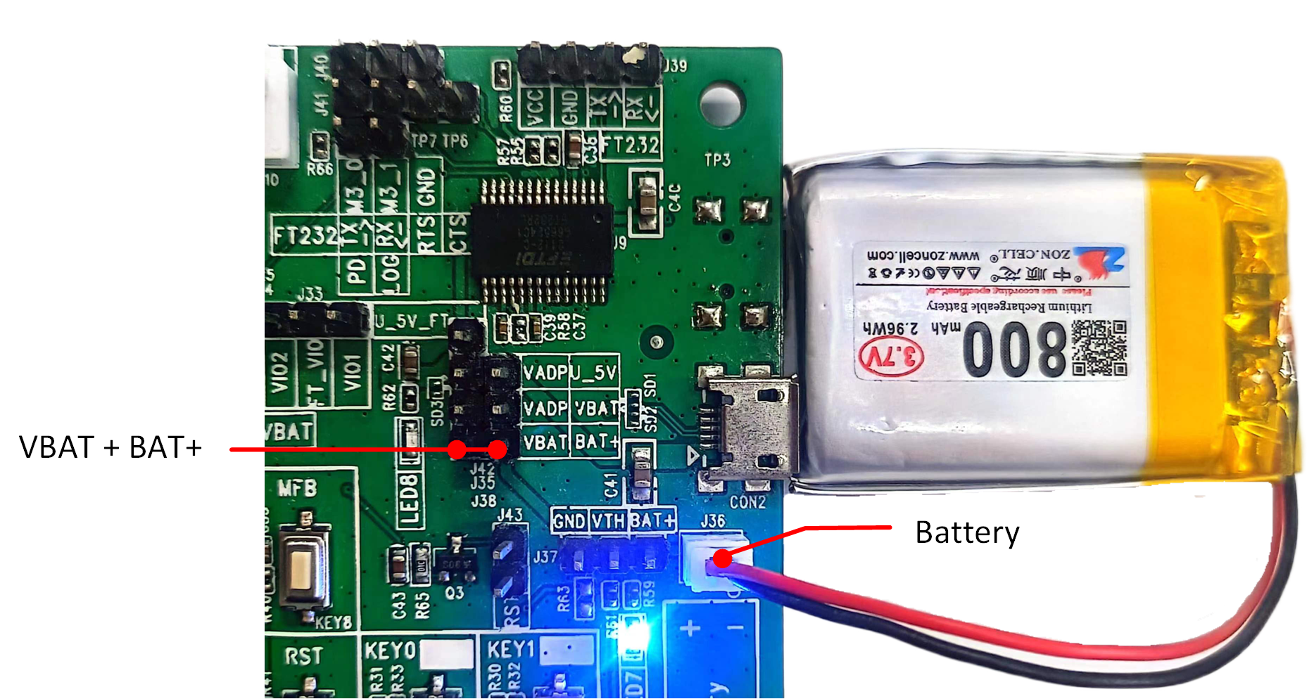
Battery Power
SWD
The introduction of SWD related content is as follows.
RTL87x3 |
SWD |
|---|---|
GND |
GND |
IO |
SWIO |
CLK |
SWCK |
VDD |
Vterf/3.3V |
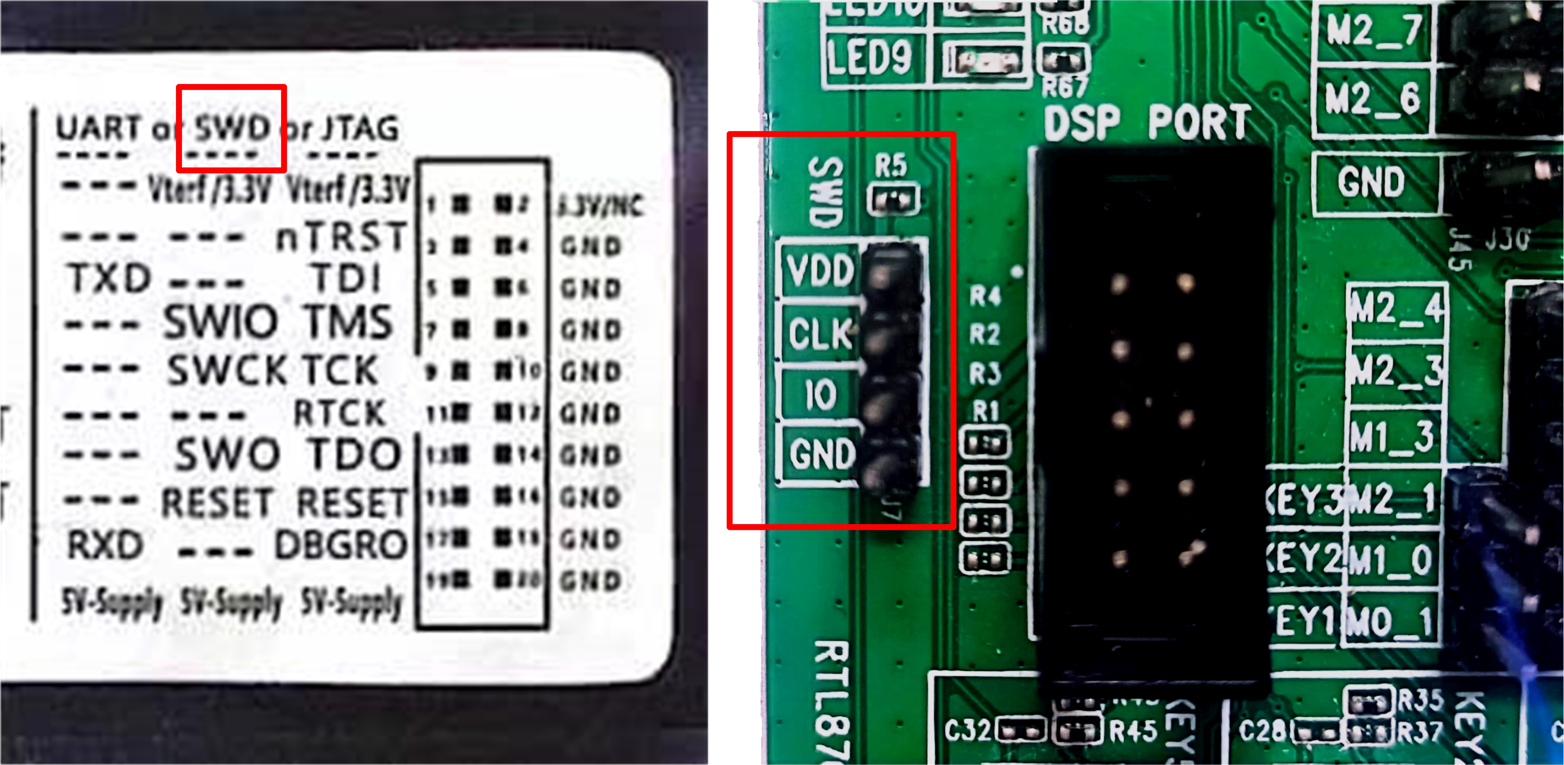
SWD
UART
UART pin layout is shown in the following figure.
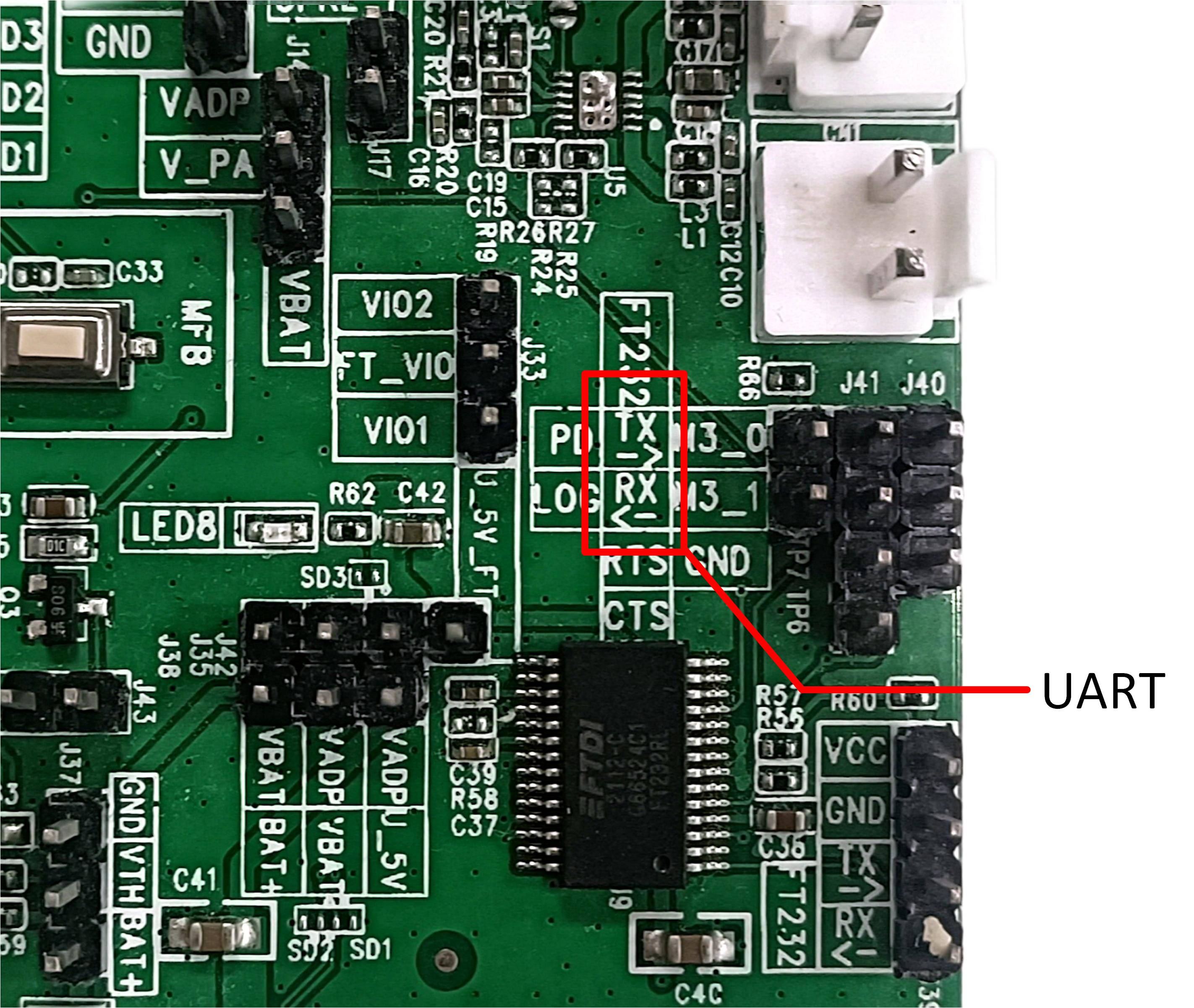
UART
Reset
Reset button is shown in the following figure.
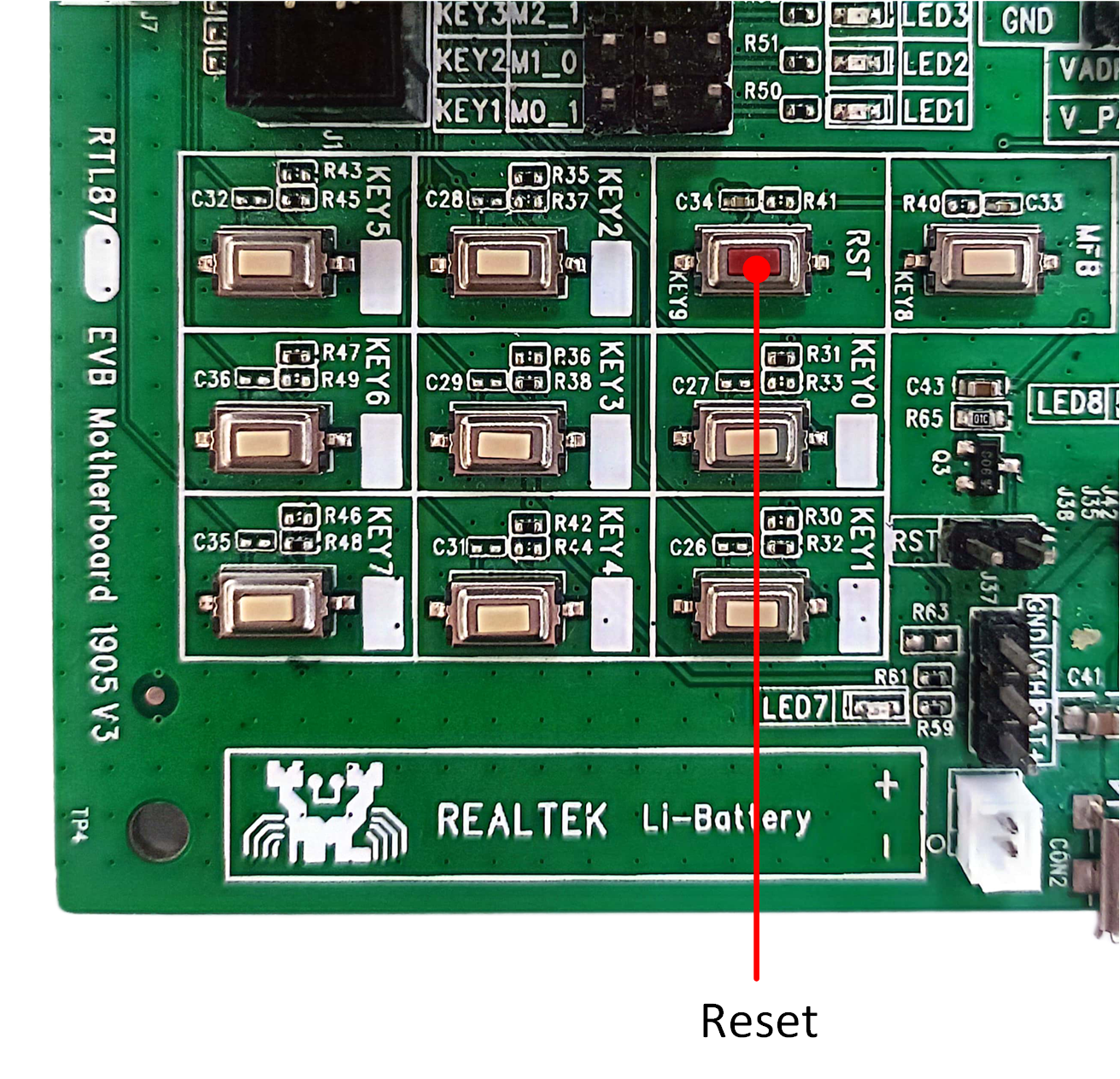
Reset
Microphones
When using the MIC1 jack for electret condenser microphone input, please follow the steps below:
Short the pins of J22 and J24 respectively.
Connect J25.1 to terminal 1(+) of the microphone.
Connect J23.1 to terminal 2(-) of the microphone.
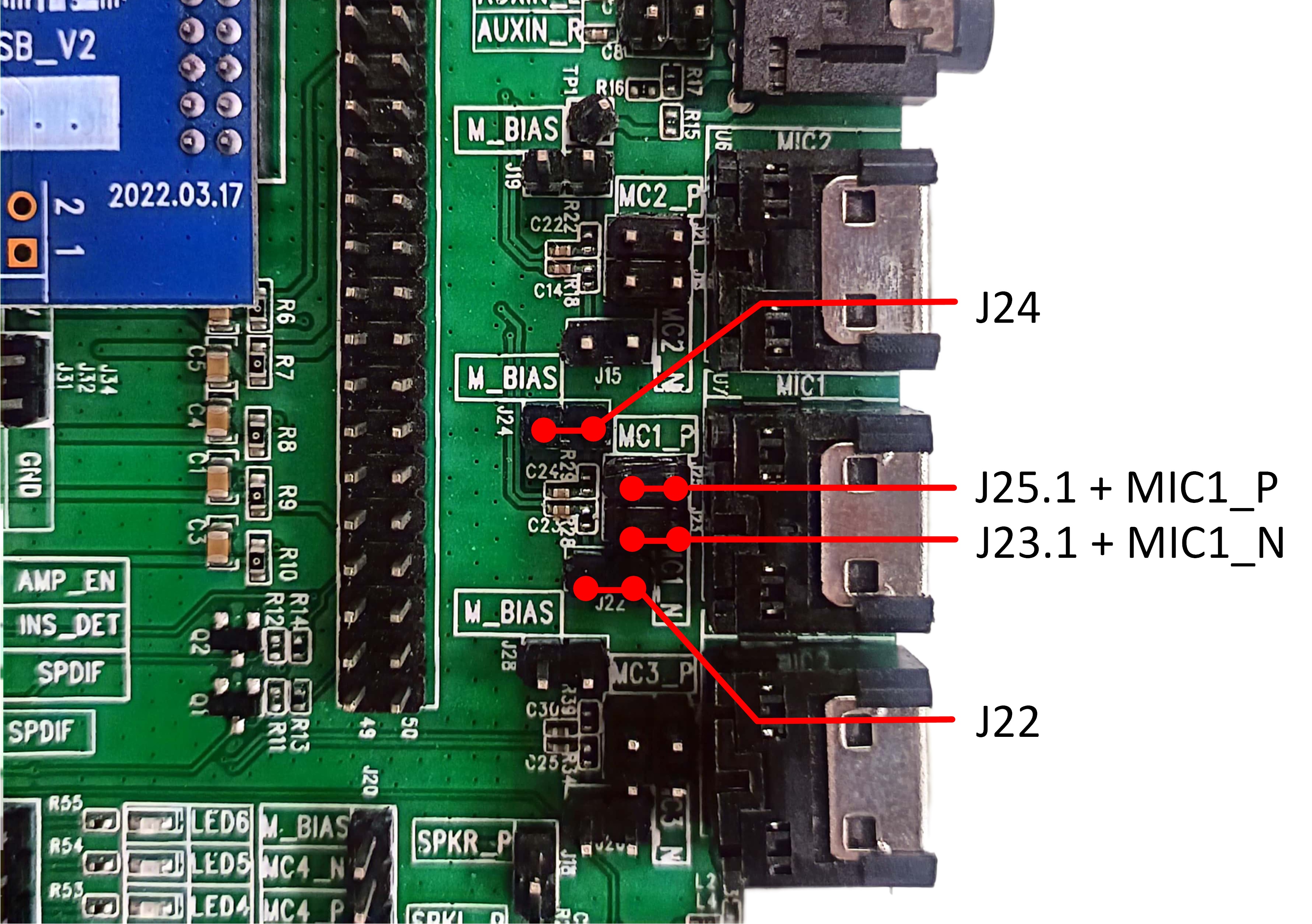
MIC1
The wire map for the MIC2/MIC3 jack is similar to that of the MIC1 jack.
Headphone
When using the headphone jack for headphone output, please follow the steps below:
Connect J9.3 to J9.2.
Short J8 and J13.
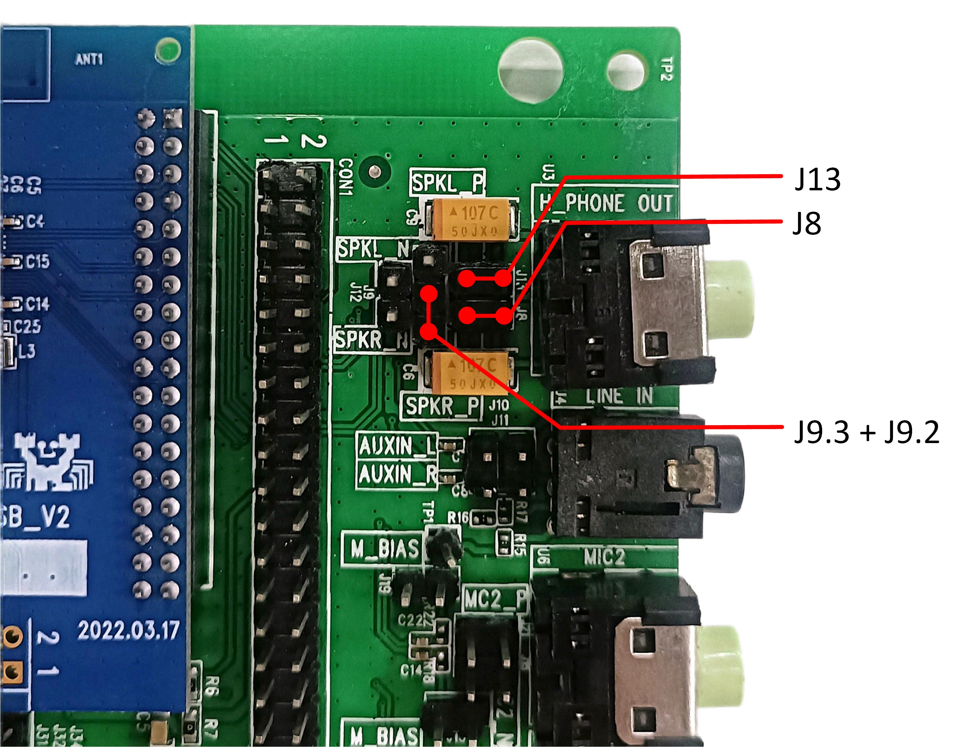
Headphone
Log Pin Wiring
When using FT232 on EVB for log, please follow the steps below:
Connect TP6 LOG (equivalent to the default log pin M2_0) and J41.3 RX.
Connect the USB connector CON3 on the bottom side to PC as USB to UART input.
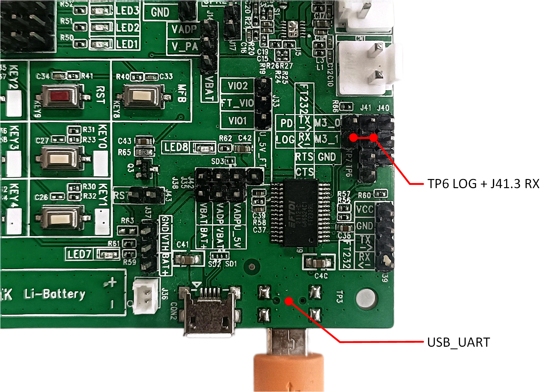
Log Pin
Download Mode
Connect USB connector CON3 on the bottom side to PC as USB to UART input and supply power for the EVB, as introduced in Power Supply.
Make sure J33.2 FT_VIO is connected to J33.1 VIO1 (3.3V fixed, VDDIO0/LDO_HV33 in spec) to guarantee the voltage consistency.
Use jumpers to connect J40.1 M3_0 to J41.4 TX and connect J40.2 M3_1 to J41.3 RX (M3_0 and M3_1 are fixed and cannot be changed).
-
Connect TP6 LOG to TP7 PD and then push RST key to reset SoC.
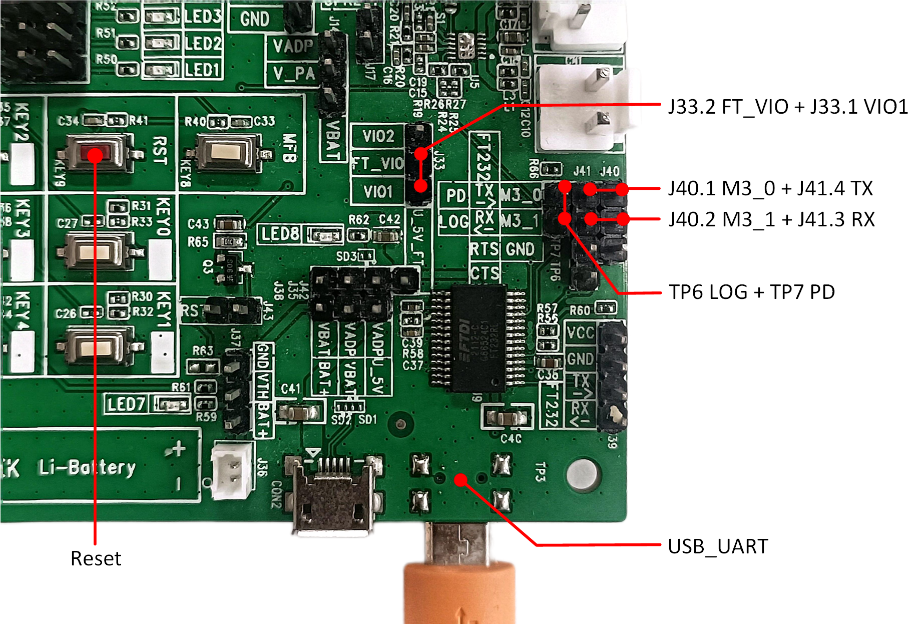
Download Mode
After entering the download mode, please refer to MPPG Tool Download for instructions on how to download the program.
Normal Mode
Supply power for the EVB, as introduced in Power Supply.
-
Connect J33.2 FT_VIO to J33.3 VIO2/J33.1 VIO1 (1.8V/3.3V selectable according to the LDOAUX setting in MCUConfig Tool) to guarantee the voltage consistency.

LDOAUX Setting
Disconnect TP6 LOG and TP7 PD (see Download Mode).
-
Pull off all the jumpers between J40 and J41.
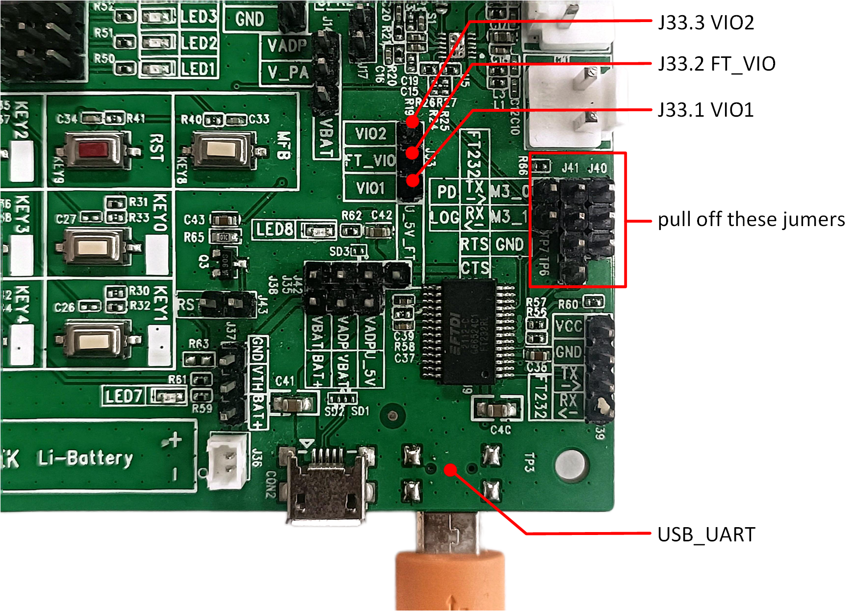
Normal Mode
If printing logs is required, please refer to Log Pin Wiring.
Building and Downloading
The default files for RTL87x3 are as introduced in Required Files.
The Boot Patch Image, DSP APP Image, DSP SYS Image, FSBL Image, Bluetooth Controller EXT Image, Platform EXT Image, Stack Patch Image, SYS Patch Image, Bluetooth Host Image, and Patch Image are provided by Realtek. Users can download the above information through Anchor which is a release system from Realtek. If there is no Anchor account, please apply for registration from the agent/PM/FAE. Alternatively, users can also download these files directly from the Realtek official website:
For RTL87x3E series, please visit https://www.realmcu.com/en/Resources/sdk/RTL8763E-Series.
For RTL87x3D series, please visit https://www.realmcu.com/en/Resources/sdk/RTL8773D-Series.
For RTL87x3EP series, please visit https://www.realmcu.com/en/Resources/sdk/RTL8773E-Series.
Below is a brief introduction of the default files:
-
OTA Header Image
The OTA Header Image is a file that defines the layout of the Flash Bank. It is generated by the MPPG Tool.
-
Boot Patch Image
The Boot Patch Image is provided by Realtek. The ROM code reserves the Patch function entry point, which can be used to optimize the boot flow, modify the behavior of the secure ROM code, and expand the functionality of the ROM code.
-
DSP APP Image
Default DSP application code for project. It could be replaced by the same file generated via DSP SDK.
-
DSP SYS Image
Default DSP system code for sample project. It is reserved by Realtek.
-
DSP Configuration Image
Default DSP UI parameter file for sample project. It could be replaced by the same file generated via DSPConfig Tool.
-
FSBL Image
The binary file is an experimental bootloader which is only needed for the development phase.
-
Bluetooth Controller EXT Image
Extended for Bluetooth Controller stack code.
-
Platform EXT Image
Extended for platform code.
-
Stack Patch Image
The Stack Patch Image is a file provided by Realtek that supports features related to the Bluetooth Controller stack.
-
SYS Patch Image
The SYS Patch Image is a file provided by Realtek. The ROM code reserves the Patch function entry point, which allows modifications to the behavior of the non-secure ROM code and the expansion of ROM code functionality.
-
Bluetooth Host Image
Default Bluetooth Host code for sample project.
-
Patch Image
Realtek's internal code for stack bug fixing or feature extension. It is necessary for any project.
-
APP Configuration Image
Default application UI parameter file for sample project. It could be replaced by the same file generated via MCUConfig Tool.
-
System Configuration Image
Default system configuration UI parameter file for sample project. It could be replaced by the same file generated via MCUConfig Tool.
-
VPData Configuration Image
Default voice prompt file for sample project. It could be replaced by the same file generated via MCUConfig Tool.
-
User Data Image
The User Data Image contains the GUI resources that users need to index and use in the MCU, mainly including images and fonts. This bin file is closely tied to the screen display effect.
-
APP Demo Image
The APP Demo Image is an application developed by the developer. It is built from Keil/GCC project and processed using tools like fromelf.
Note
Please store the SDK, tools, and other related materials in a path that does not contain any spaces or Chinese characters.
-
Before downloading the files, users need to load the
flash_map.inifile, which represents the allocation of addresses for each file in the flash. Users can generate theflash_map.inifile by clicking on Flash Map Generator on the MPPG Tool interface, as shown in the following figure.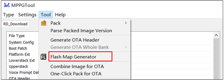
Flash Map Generator
-
If Chip Erase is clicked, the flash memory will be completely erased before writing. If this button is not clicked, only the area of files that are being downloaded will be erased from the flash, as shown below.
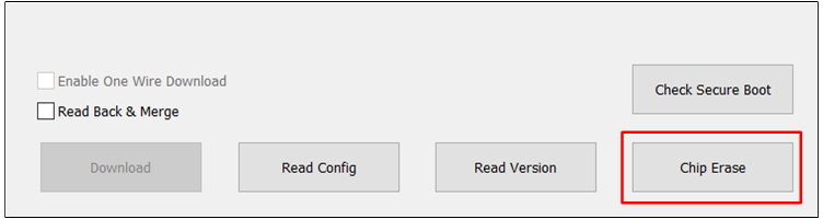
Chip Erase
Generating Flash Map
The flash map.ini file can be generated in the ways introduced in Configure Flash Layout.
If there are no parameters to modify, users can skip this section and directly load the default file from the SDK.
Taking RTL8763ESE as an example, the flash map is located at: \bin\rtl87x3e\flash_map_config\4M\flash_4M\flash_map.ini.
Note
Different flash sizes (1M/4M/16M, etc.) correspond to different flash maps.
Generating OTA Header
The OTA Header File can be generated in the ways introduced in Generate OTA Header.
If there are no parameters to modify, users can skip this section and directly load the default file from the SDK.
Taking RTL8763ESE as an example, the OTA Header File is located at: \bin\rtl87x3e\8763ESE\4M\BANK0\OTAHeader_Bank0_xxx.bin.
Generating MCU Configuration File
The APP configuration file, system configuration file, and VPData configuration file can be generated in the ways introduced in MCUConfig Tool.
If there are no parameters to modify, users can skip this section and directly load the default file from the SDK.
Taking RTL8763ESE as an example, the MCU configuration file is located at: \bin\rtl87x3e\8763ESE\4M\rcfg\For EVB.
Generating APP Image
The basic settings for all applications in the SDK have been configured, so users can directly open them and build through Keil MDK/GCC. Before starting software development, it is necessary to install the Keil/GCC compilation environment. It is generally not recommended to create a new project, but to directly open an existing example project and add functional code on top of it.
Keil MDK
Keil MDK is the complete software development environment for a range of ARM Cortex-M based microcontroller devices. MDK includes the µVision IDE and debugger, ARM C/C++ compiler, and essential middleware components.
All applications in the SDK can be built and developed using the Keil MDK. Therefore, before starting software development, users need to obtain and install Keil. For more information about Keil, please visit https://www.keil.com/.
The toolchain version information used by Realtek is shown in the following figure. To avoid compatibility issues between ROM executables and applications, it is recommended to use μVision V5.36 or a later version.
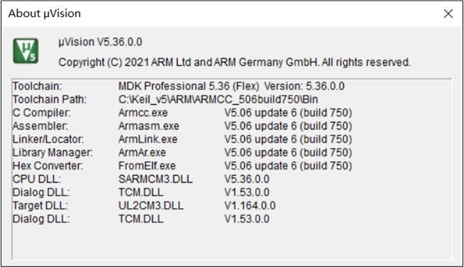
Tool Chain
Configure the default compiler to ARMCC_506build750, as shown below.
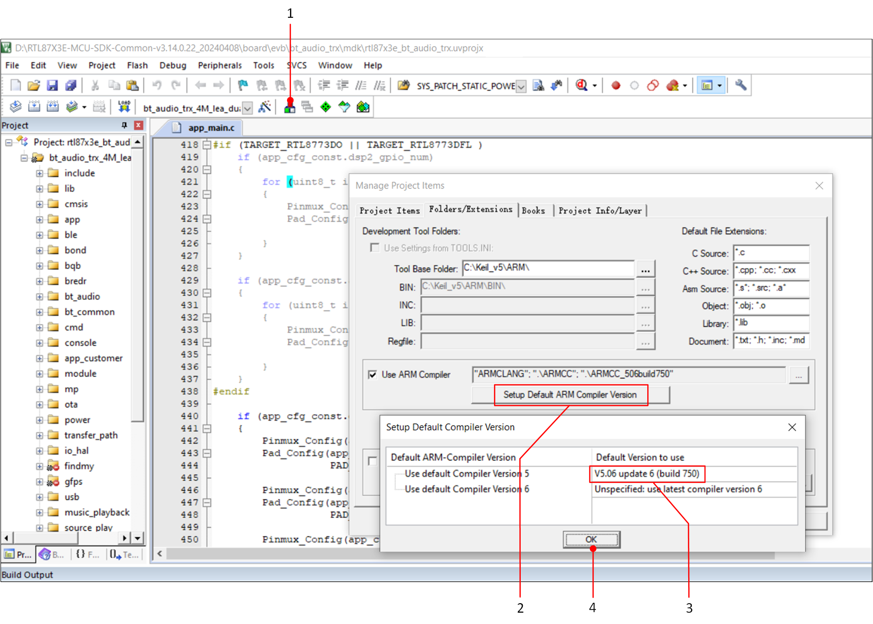
Default Compiler
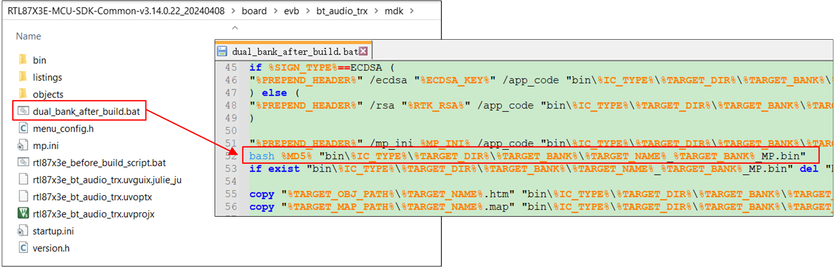
In each project, there could be multiple targets that require selection before building. Taking bt_audio_trx project as an example, after successful building, a bin file with MD5 verification will be generated in the bin folder of the project, as shown in the following figures.
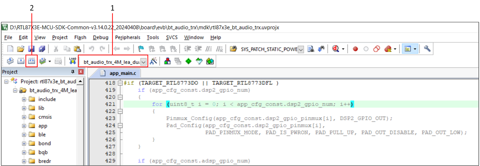
bt_audio_trx Compile
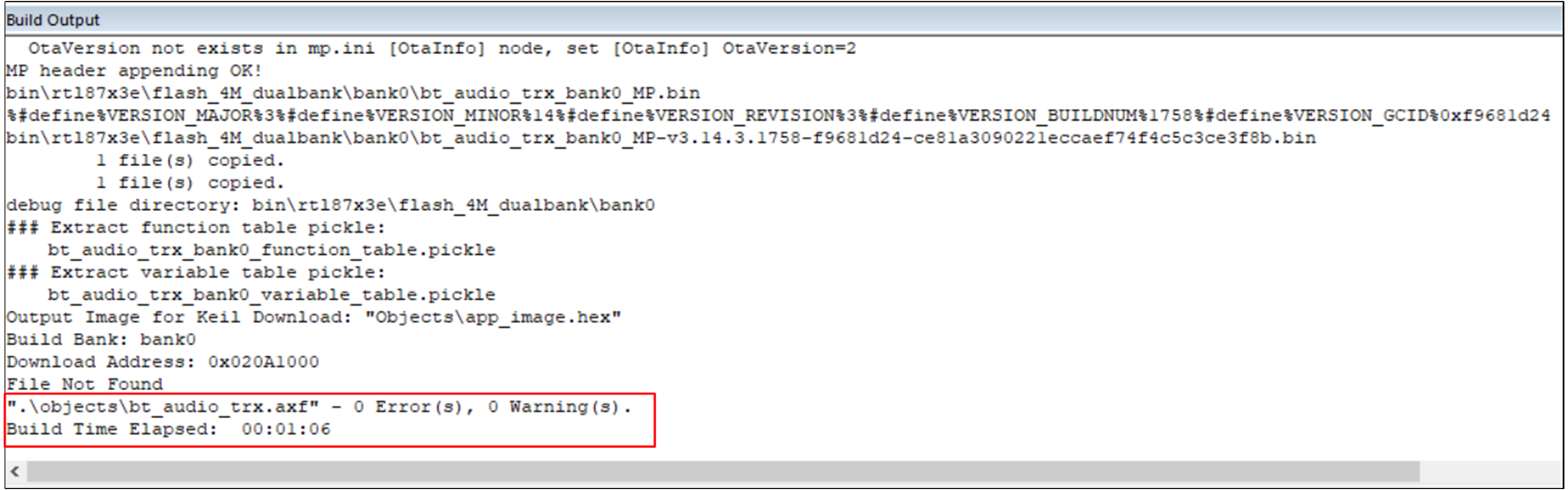
Build Output
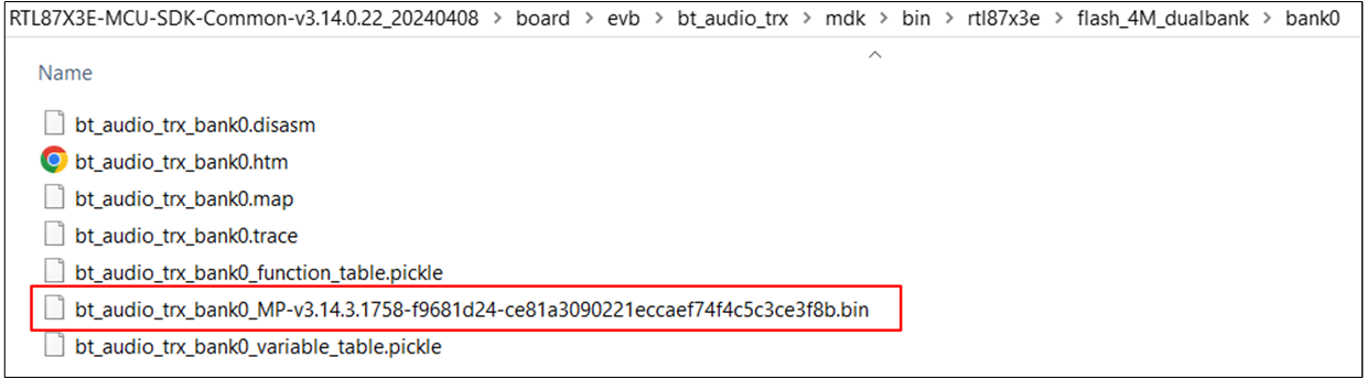
bt_audio_trx Bin
Note
MPPG Tool uses MD5 as the checksum value for the files and requires adding the MD5 value to the suffix of the file name to be downloaded.
Therefore, the downloading file is an APP Image with the prefix MP.
GCC
Please refer to Environment Setup to configure the environment and compile the GCC project.
Images Download
This chapter describes two methods for downloading images.
MPPG Tool Download
Please refer to MPPG Tool to use MPPG Tool to download the files onto the device.
J-Link Download
J-Link is a debugger/simulator developed by SEGGER. It is a specialized tool for ARM processors and is used for the development, debugging, and testing of firmware on embedded devices. It offers high-speed and reliable simulation performance, supporting real-time debugging and fast firmware downloading. J-Link can help developers accelerate the debugging and validation process of embedded systems, improving efficiency and quality in development.
J-Link supports various connection interfaces such as JTAG, SWD, etc. Due to SWD requiring fewer connections, the RTL87x3 utilizes this interface. Additionally, J-Link is compatible with multiple development environments and IDEs such as Keil MDK, IAR Embedded Workbench, etc. The setup instructions for the Keil environment can refer to Keil MDK.
J-Link Software v6.44 (or later) is recommended, for more information, please refer to Debug.
For SWD connection, please refer to SWD. After the SWD connection is completed, users can download APP image through J-Link, please make sure that the rest of the images have been downloaded through MPPG Tool, which can be referred to MPPG Tool Download. Then users can refer to Download with Keil to use J-Link downloading.
Note
SWD is more suitable for debugging IO peripheral drivers and platform-related issues, but it is not recommended for debugging Bluetooth-related applications. This may disrupt the normal state of Bluetooth and result in lower debugging efficiency. Therefore, it is recommended to use Debug Analyzer instead.
Example Verification
Taking the bt_audio_receiver project in \bin\rtl87x3e\app_demo_bin\mdk\bt_audio_trx\4M\bt_audio_receiver\BANK0 as an example.
Mobile APP Verification
For the hardware peripheral wiring of the EVB, users can refer to EVB Interfaces and Modules and Download Mode. To download files, please refer to MPPG Tool Download. After completing the above steps, please press the Reset button on the EVB or power-cycle the EVB. Users can use the ACI Host CLI Tool that comes with bt_audio_trx and enter the command mode all_enable. For detailed instructions, please refer to Connect to Phone.
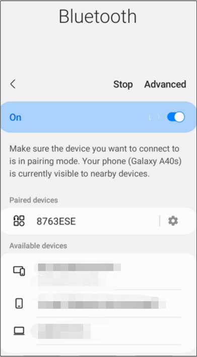
Then users can search for Bluetooth devices through the Bluetooth settings interface on their smartphones. The default device name is 8763ESE, as shown in the following figure. Click on the desired device to establish a connection. Once both the phone and the device confirm the connection, the smartphone will display a successful connection message.
Connect Device
Log Verification
Users can use Debug Analyzer to capture the SoC Log to check whether the program is running correctly.
For details about Log connection, please refer to Log Pin Wiring.
Debug Analyzer is located at: \tool\DebugAnalyzer-vx.x.x.x, as shown in the following figure.
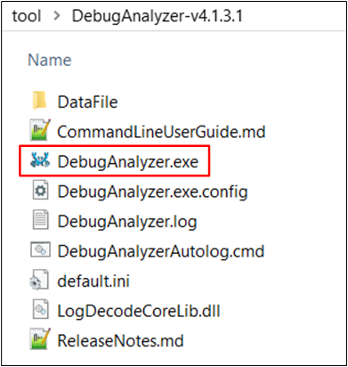
Debug Analyzer
Double-click to run DebugAnalyzer.exe, click Setting, Baud rate is set to 2M by default, and load the corresponding .trace file in the App Trace File.
Then click Confirm to confirm the settings, as shown in the following figure.
The trace file is located at: \trace\app_demo_bin\mdk\bt_audio_trx\4M\bt_audio_receiver\BANK0\bt_audio_trx_bank0.trace.
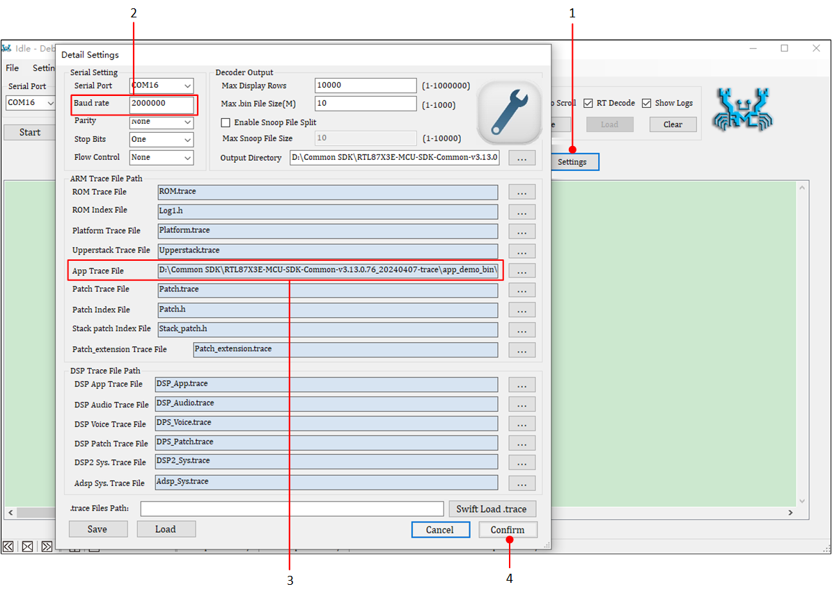
Debug Analyzer Settings
Select the correct Serial Port, click on Start, and Debug Analyzer will start working.
It will save the captured raw data in a .bin file, and based on the user's settings for the .trace file, it will parse the raw data into plain text logs and save them in a .log file.
Taking the bt_audio_receiver project as an example, after powering on the EVB board and successfully connecting the Bluetooth device, the following log message app_bond_get_pair_idx_mapping success will be displayed.
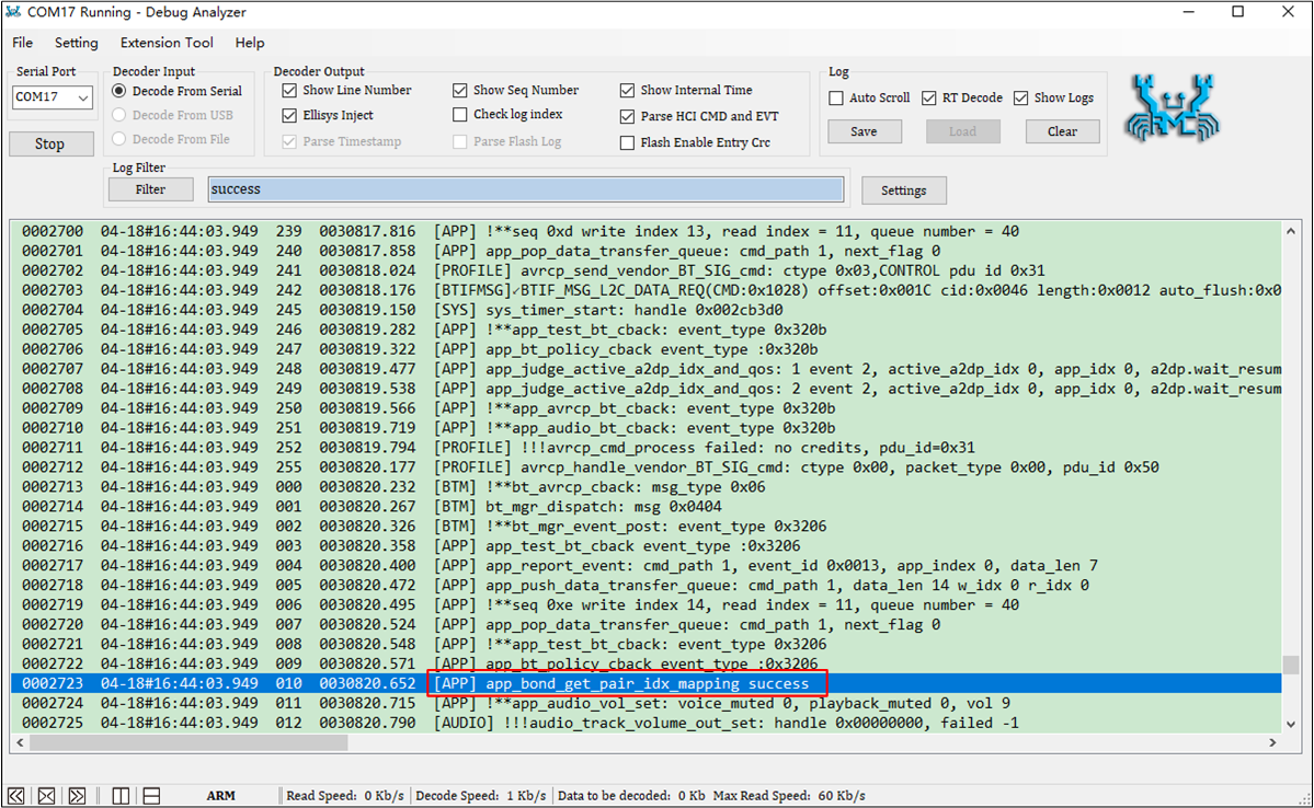
Connect Success
While using a mobile phone to play music, the device's speaker will output the audio. Additionally, the Debug Analyzer will display the following log messages media_buffer_write and audio_track_path_cback: handle as verification.
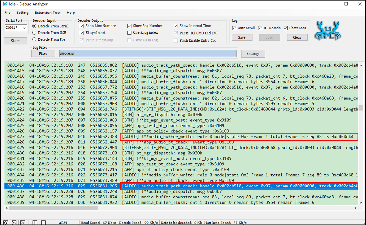
A2DP Music Play
Note
-
Default save path: the DataFile folder in the same directory as
DebugAnalyzer.exe, as shown below.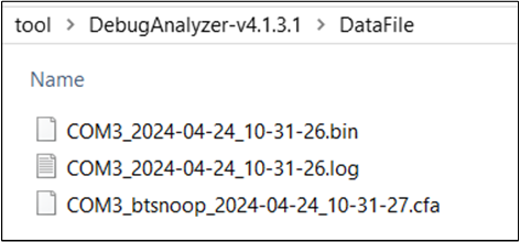
Log Location
Make sure the
.tracefile matches the current SoC running image.If users encounter any issues during the development process, please provide the
.log,.binand.cfafiles located inDebugAnalyzer\DataFiledirectory, as well as the corresponding.tracefile. This will help Realtek analyze and locate the issue more effectively.