Image Layout
This document provides an introduction to image layout, covering the following two aspects:
-
Flash Layout
Overview of the image layout in Flash, aiming to prevent misuse.
Steps on how to adjust the Flash layout.
-
Image Data Layout
Introduce parts in images.
Flash Layout
In order to use the Flash more conveniently and prevent misuse, Flash layout is introduced.
RTL87x3E Flash Layout
Images can be divided into two categories: High Level Images and Bank Images.
RTL87x3E Flash layout indicates the start address and max size of images in Flash:
The configurations of the System Config Image and Boot Patch Image are fixed in the ROM and can't be changed.
The configurations of Platform EXT Image, Bluetooth Controller EXT Image, and Bluetooth Host Image are recorded in Boot Patch Image and can't be changed.
The System Config Image records the layout of high level images.
The OTA Header defines the layout of images in the same bank.
High Level Images
The high level images of Flash layout are shown in the following figure:
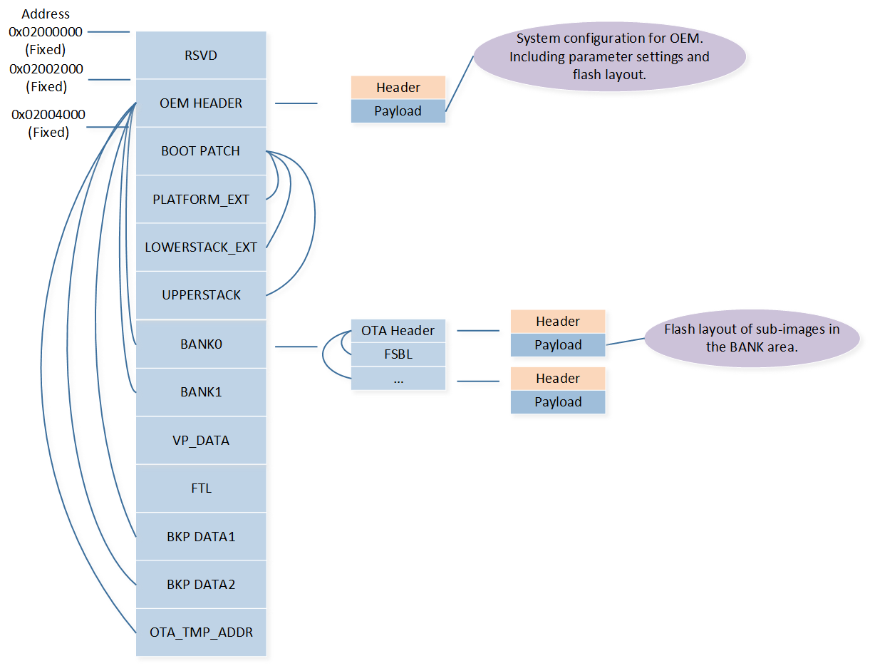
High Level Images of RTL87x3E
Note
After the Flash map is modified, please make sure to regenerate the related images.
The Flash layout of all images should not overlap. The Flash layout size of the image should be larger than the image size. It is also suggested to be aligned by Flash sector size (0x1000 bytes). If two images share one Flash sector, they should download together, as the minimum Flash erase size is the Flash sector size.
Let's take the 4M Flash map as an example to show the description of the Flash layout in the following map:
Memory Segment |
Starting Address |
Size (Bytes) |
Functions |
|---|---|---|---|
Reserved |
0x02000000 |
0x00002000 |
Reserved. |
System Config Image |
0x02002000 |
0x00002000 |
Stores configuration information, which includes Bluetooth Address and user defined Flash layout. |
Boot Patch Image |
0x02004000 |
0x00002000 |
Flash boot loader. |
Platform EXT Image |
0x02006000 |
0x00008000 |
Stores Platform extension information. |
Bluetooth Controller EXT Image |
0x0200E000 |
0x00007000 |
Stores Bluetooth Controller extension information. |
Bluetooth Host Image |
0x02015000 |
0x0003F000 |
Stores Bluetooth Host information. |
Bank0 Images |
0x02054000 |
0x001AC000 |
Stores data and code running area, further subdivided into OTA Header, FSBL, Stack Patch, System Patch, APP, DSP System, DSP APP, DSP Config, APP Config, and EXT images. |
Bank1 Images |
0x02200000 |
0x001AC000 |
The same as Bank0 Images, and the size of Bank1 Images must also be the same as Bank0 Images. |
VPData |
0x023AC000 |
0x00032000 |
Stores VP data. |
FTL |
0x023DE000 |
0x00015000 |
Supports accessing Flash with a logical address. Users can read/write Flash with a unit size of at least 4 bytes. |
Backup Data1 |
0x00000000 |
0x00000000 |
Optional to use. Stores any data. |
Backup Data2 |
0x023FE000 |
0x00002000 |
Optional to use. Stores any data. |
OTA Temp |
0x00000000 |
0x00000000 |
Optional to use. For OTA. |
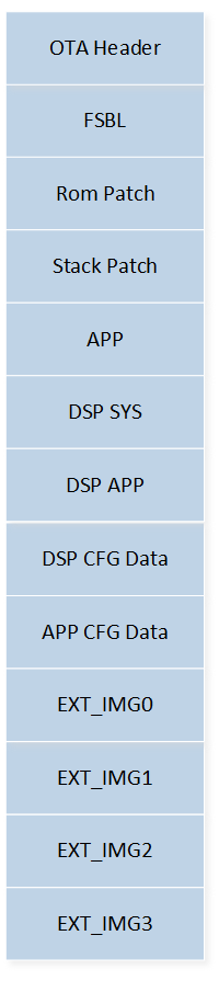
Bank Images
For RTL87x3E, Bank0 Images can be subdivided into the following images:
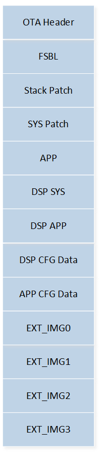
Bank0 Layout for RTL87x3E
Memory Segment |
Starting Address |
Size (Bytes) |
Functions |
|---|---|---|---|
OTA Header |
0x02054000 |
0x00000400 |
OTA version, start address, and size of each bank. |
FSBL |
0x02054400 |
0x00001C00 |
Flash secure boot loader. |
Stack Patch |
0x02056000 |
0x0003D000 |
Stack optimization and extension code. |
System Patch |
0x02093000 |
0x0001D000 |
Optimized and expanded code for systems in non-secure ROM. |
APP |
0x020B0000 |
0x000DE000 |
Running code for development solutions. |
DSP System |
0x0218E000 |
0x00020000 |
DSP system information. |
DSP APP |
0x021AE000 |
0x00038000 |
DSP running code. |
DSP Config |
0x021E6000 |
0x0000A000 |
DSP configuration information. |
APP Config |
0x021F0000 |
0x00002000 |
APP configuration information. |
EXT Image0 |
0x021F2000 |
0x0000A000 |
Optional to use. Stores any data. |
EXT Image1 |
0x021FC000 |
0x00004000 |
Optional to use. Stores any data. |
EXT Image2 |
0x00000000 |
0x00000000 |
Optional to use. Stores any data. |
EXT Image3 |
0x00000000 |
0x00000000 |
Optional to use. Stores any data. |
RTL87x3EP Flash Layout
Images can be divided into two categories: High Level Images and Bank Images.
RTL87x3EP Flash layout indicates the start address and max size of images in Flash:
The configurations of the System Config Image and Boot Patch Image are fixed in the ROM and can't be changed.
The configurations of Platform EXT Image, Bluetooth Controller EXT Image, and Bluetooth Host Image are recorded in Boot Patch0 Image and Boot Patch1 Image and can't be changed.
The System Config Image records the layout of high level images.
The OTA Header defines the layout of images in the same bank.
High Level Images
The high level images of the Flash layout are shown in the following figure:
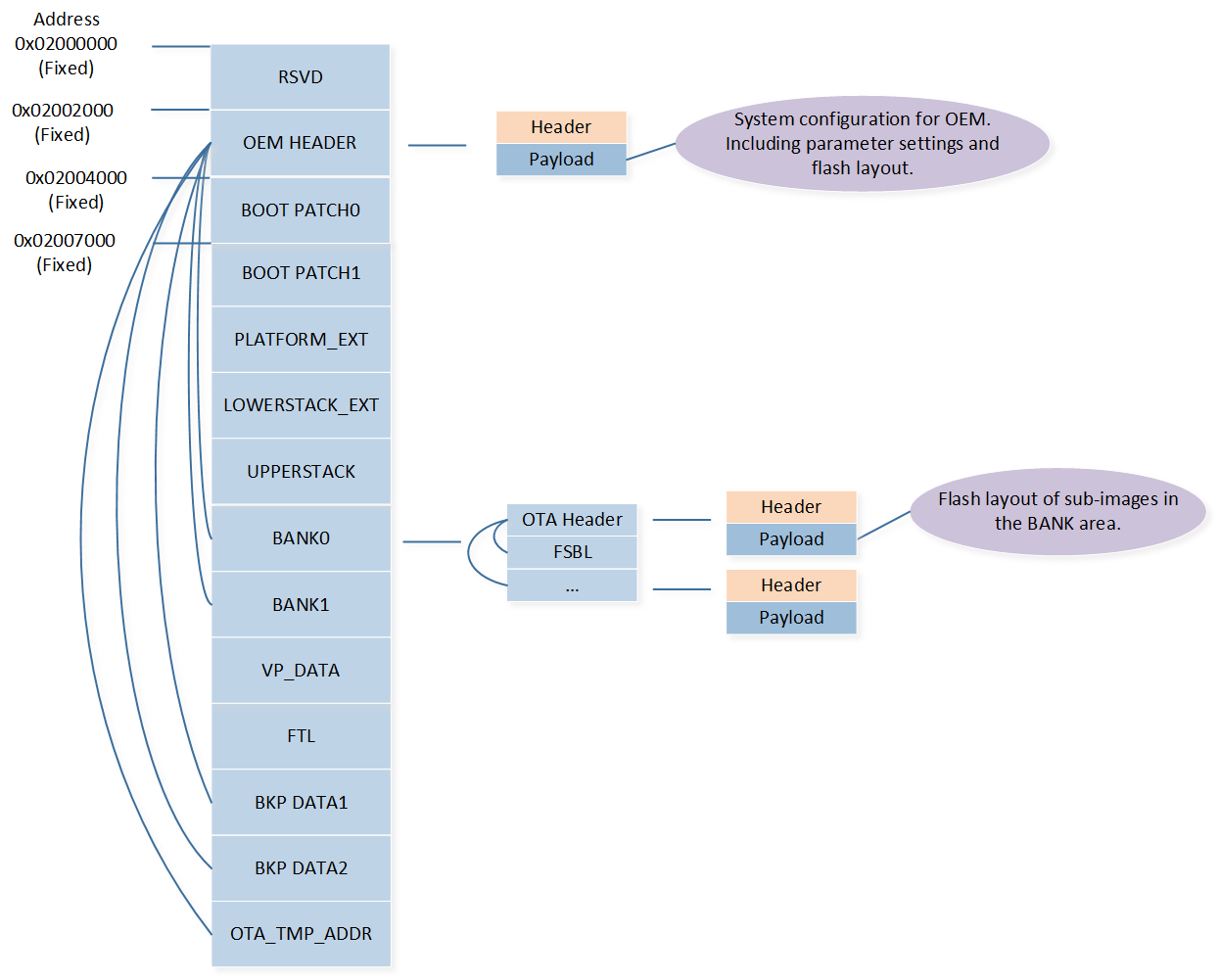
High Level Images of RTL87x3EP
Note
The Boot Patch0 Image and Boot Patch1 Image should exist at the same time.
After the Flash map is modified, please make sure to regenerate the related images.
The Flash layout of all images should not overlap. The Flash layout size of the image should be larger than the image size. It is also suggested to be aligned by Flash sector size (0x1000 bytes). If two images share one Flash sector, they should download together, as the minimum Flash erase size is the Flash sector size.
Let's take the 4M Flash map as an example to show the detailed description of the Flash layout in the following map:
Memory Segment |
Starting Address |
Size (Bytes) |
Functions |
|---|---|---|---|
Reserved |
0x02000000 |
0x00002000 |
Reserved. |
System Config Image |
0x02002000 |
0x00002000 |
Stores configuration information which includes Bluetooth Address and user defined Flash layout. |
Boot Patch0 Image |
0x02004000 |
0x00003000 |
Flash boot loader. |
Boot Patch1 Image |
0x02007000 |
0x00003000 |
Flash boot loader. |
Platform EXT Image |
0x0200A000 |
0x00008000 |
Stores Platform extension information. |
Bluetooth Controller EXT Image |
0x02012000 |
0x0000D000 |
Stores Bluetooth Controller extension information. |
Bluetooth Host Image |
0x0201F000 |
0x0003F000 |
Stores Bluetooth Host information. |
Bank0 Images |
0x0205E000 |
0x001AC000 |
Stores data and code running area, further subdivided into OTA Header, Stack Patch, System Patch, APP, DSP System, DSP APP, DSP Config, APP Config, and EXT images. |
Bank1 Images |
0x0220A000 |
0x001AC000 |
The same as Bank0 Images, and the size of Bank1 Images must also be the same as Bank0 Images. |
VPData |
0x023B6000 |
0x00032000 |
Stores VP data. |
FTL |
0x023E8000 |
0x00008000 |
Support accessing Flash with logic address. User can read/write Flash with a unit size of 4 bytes at least. |
Backup Data1 |
0x00000000 |
0x00000000 |
Optional to use. Stores any data. |
Backup Data2 |
0x00000000 |
0x00000000 |
Optional to use. Stores any data. |
OTA Temp |
0x00000000 |
0x00000000 |
Optional to use. For OTA. |
Bank Images
For RTL87x3EP, Bank0 Images could be subdivided into the following images:

Bank0 Layout for RTL87x3EP
Memory Segment |
Starting Address |
Size (Bytes) |
Functions |
|---|---|---|---|
OTA Header |
0x02054000 |
0x00000400 |
OTA version, start address, and size of each bank. |
Stack Patch |
0x02056000 |
0x0003D000 |
Stack optimization and extension code. |
System Patch |
0x02093000 |
0x0001D000 |
Optimized and expanded code for systems in non-secure ROM. |
APP |
0x020B0000 |
0x000DE000 |
Running code for development solutions. |
DSP System |
0x0218E000 |
0x00020000 |
DSP system information. |
DSP APP |
0x021AE000 |
0x00038000 |
DSP running code. |
DSP Config |
0x021E6000 |
0x0000A000 |
DSP configuration information. |
APP Config |
0x021F0000 |
0x00002000 |
APP configuration information. |
EXT Image0 |
0x021F2000 |
0x0000A000 |
Optional to use. Stores any data. |
EXT Image1 |
0x021FC000 |
0x00004000 |
Optional to use. Stores any data. |
EXT Image2 |
0x00000000 |
0x00000000 |
Optional to use. Stores any data. |
EXT Image3 |
0x00000000 |
0x00000000 |
Optional to use. Stores any data. |
RTL87x3D Flash Layout
Images can be divided into two categories: High Level Images and Bank Images.
RTL87x3D Flash layout indicates the start address and max size of images in Flash:
The configurations of the System Config Image and Boot Patch Image are fixed in the ROM and can't be changed.
The System Config Image records the layout of high level images.
The OTA Header defines the layout of images in the same bank.
High Level Images
The high level images of Flash layout is shown in the following figure:
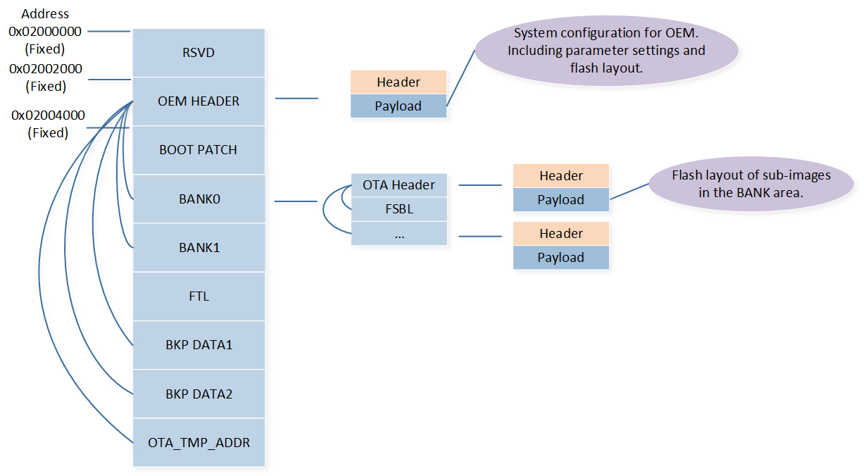
High Level Images of RTL87x3D
Note
After the Flash map is modified, please make sure to regenerate the related images.
The Flash layout of all images should not overlap. The Flash layout size of the image should be larger than the image size. It is also suggested to be aligned by Flash sector size (0x1000 bytes). If two images share one Flash sector, they should download together, as the minimum Flash erase size is Flash sector size.
Let's take the 16M Flash map as an example to show the detailed description of the Flash layout in the following map:
Memory Segment |
Starting Address |
Size (Bytes) |
Functions |
|---|---|---|---|
Reserved |
0x02000000 |
0x00002000 |
Reserved. |
System Config Image |
0x02002000 |
0x00002000 |
Stores configuration information which includes Bluetooth Address and user defined Flash layout. |
Boot Patch Image |
0x02004000 |
0x00002000 |
Flash boot loader. |
Bank0 Images |
0x02006000 |
0x00600000 |
Stores data and code running area, further subdivided into OTA Header, FSBL, Stack Patch, System Patch, APP, DSP System, DSP APP, DSP Config, APP Config, and EXT images. |
Bank1 Images |
0x02606000 |
0x00600000 |
The same as Bank0 Images, and the size of Bank1 Images must also be the same as Bank0 Images. |
FTL |
0x02C06000 |
0x0000F000 |
Support accessing Flash with logic address. User can read/write Flash with a unit size of 4 bytes at least. |
Backup Data1 |
0x00000000 |
0x00000000 |
Optional to use. Stores any data. |
Backup Data2 |
0x00000000 |
0x00000000 |
Optional to use. Stores any data. |
OTA Temp |
0x00000000 |
0x00000000 |
Optional to use. For OTA. |
Bank Images
For RTL87x3D, Bank0 Images could be subdivided into the following images:
Bank0 Layout for RTL87x3D
Memory Segment |
Starting Address |
Size (Bytes) |
Functions |
|---|---|---|---|
OTA Header |
0x02606000 |
0x00001000 |
OTA version, start address, and size of each bank. |
FSBL |
0x02607000 |
0x00003000 |
Flash secure boot loader. |
System Patch |
0x0260A000 |
0x00018000 |
Optimized and expanded code for systems in non-secure ROM. |
Stack Patch |
0x02622000 |
0x00040000 |
Stack optimization and extension code. |
APP |
0x02662000 |
0x00160000 |
Running code for development solutions. |
DSP System |
0x027C2000 |
0x000B0000 |
DSP system information. |
DSP APP |
0x02872000 |
0x00060000 |
DSP running code. |
DSP Config |
0x028D2000 |
0x00005000 |
DSP configuration information. |
APP Config |
0x028D7000 |
0x0001A000 |
APP configuration information. |
EXT Image0 |
0x028F1000 |
0x0000A000 |
Optional to use. Stores any data. |
EXT Image1 |
0x028FB000 |
0x002F2000 |
Optional to use. Stores any data. |
EXT Image2 |
0x00000000 |
0x00000000 |
Optional to use. Stores any data. |
EXT Image3 |
0x02BED000 |
0x00019000 |
Optional to use. Stores any data. |
Configure Flash Layout
Flash Map Generator in the MPPG Tool is designed to generate flash_map.ini and flash_map.h, which determine the Flash layout. The flash_map.ini will be used by MPPG Tool and MCUConfig Tool.
-
To generate the
flash_map.ini, open the MPPG Tool first.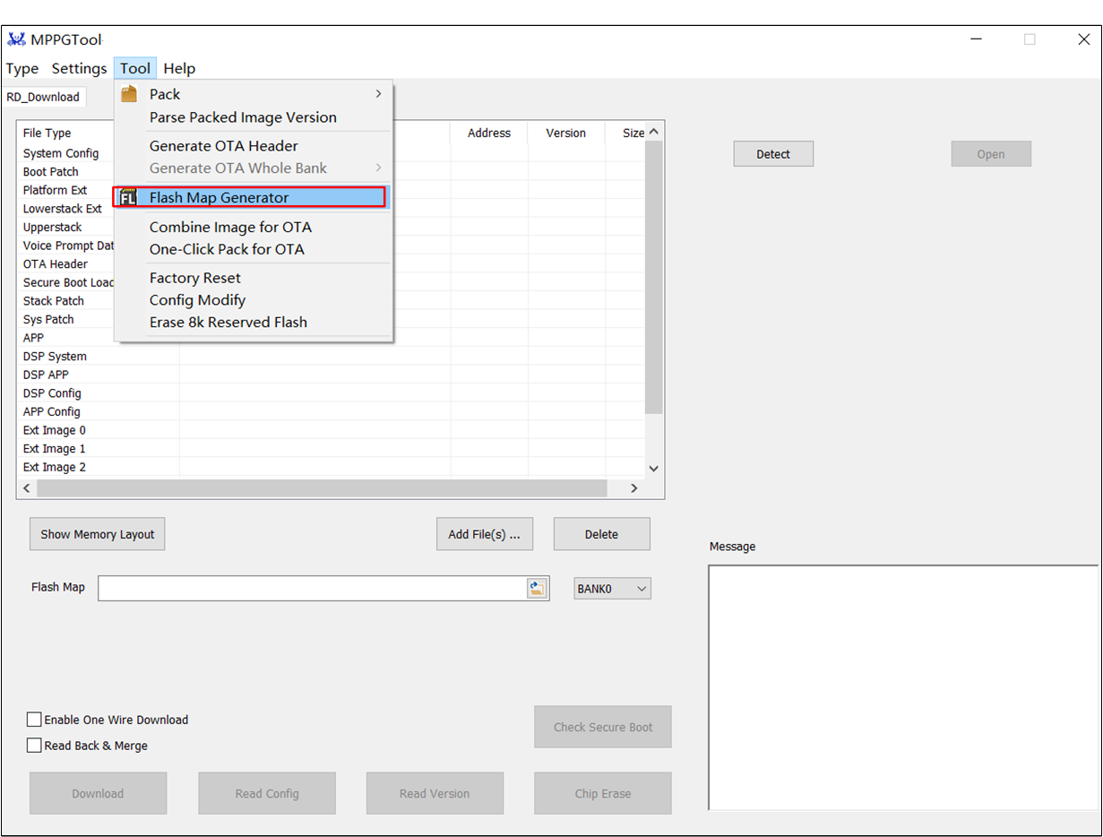
Open Flash Map Generator
-
Configure the whole Flash layout in the 'High Level Type' list and configure the layout for bank images in the 'OTA File Type' list after selecting 'Flash Size' combo box. Multi-image header size is provided in the 'Image Header Size' combo box. 'Set BP Size to Front' combo box determines which area of the Flash the BP level protects. Notice that items which 'Write Enable' is selected RW should be placed out of BP size. Import an existing
flash_map.iniby clicking the Import... and then modify the layout based on it. Lastly, click the Generate... button to generate a newflash_map.ini.For RTL87x3E, the Flash Map Generator is as follows:
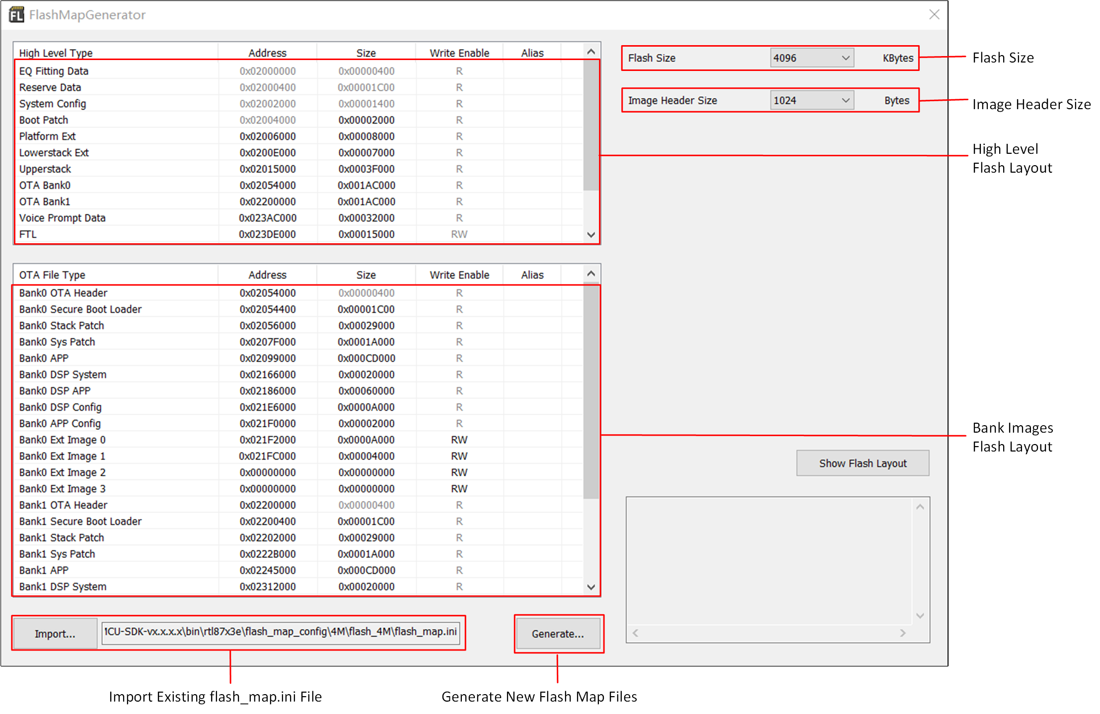
Flash Map Generator for RTL87x3E
For RTL87x3EP, the Flash Map Generator is as follows:
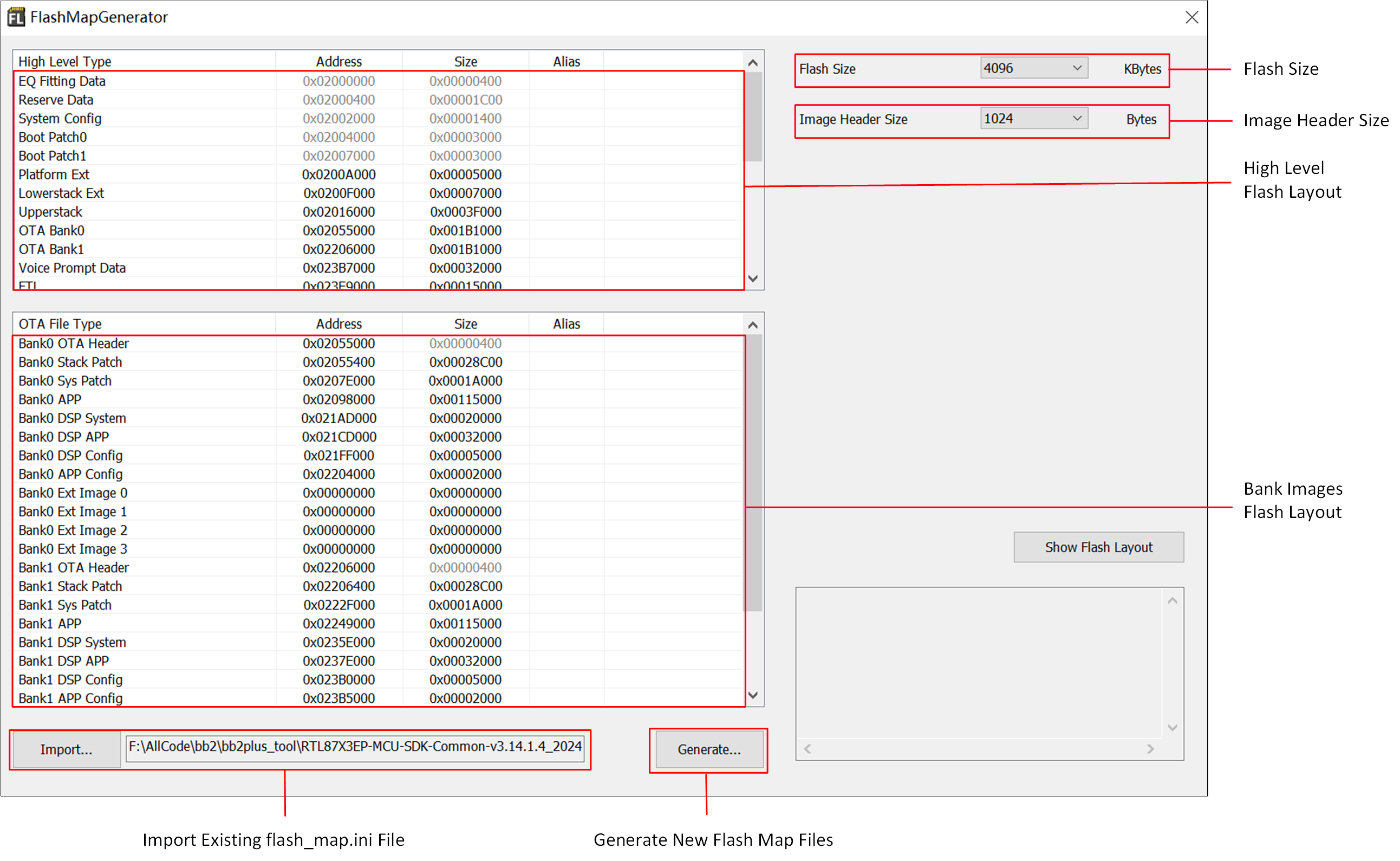
Flash Map Generator for RTL87x3EP
For RTL87x3D, the Flash Map Generator is as follows:
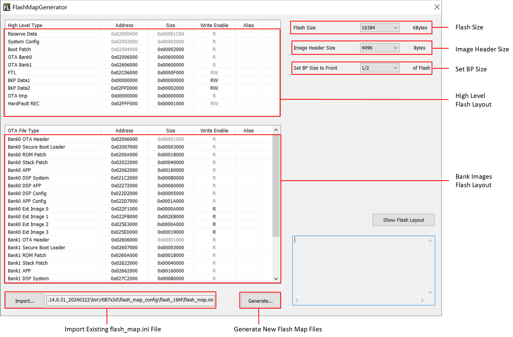
Flash Map Generator for RTL87x3D
Note
Please refer to the MPPG Tool Chain User Guide in the
tool\MPPGTooldirectory for details.
Bring New Flash Layout into Effect
Users can adjust the Flash layout in the flash_map.ini and flash_map.h through the Flash Map Generator in the MPPG Tool under the Tool. But there are some constraints for the Flash layout adjustment:
The image address and size are suggested to be aligned by 0x1000 bytes for the minimum size for Flash erase is Flash sector size. If there are two images in one Flash sector, these two images should be updated together.
Not all images' layout can be adjusted.
Constraints and Restrictions Brief
Flash layout for images can be adjusted under some constraints and restrictions according to the image types. Images can be categorized into the following types:
-
Images of Fixed Address
RTL87x3E: Boot Patch Image, Bluetooth Controller EXT Image, Platform EXT Image, Bluetooth Host Image.
RTL87x3EP: Boot Patch Image, Bluetooth Controller EXT Image, Platform EXT Image, Bluetooth Host Image.
RTL87x3D: Boot Patch Image.
The Flash address for these images can't be changed.
-
Patch Code Images
RTL87x3E: FSBL, System Patch and Stack Patch images.
RTL87x3EP: System Patch and Stack Patch images.
RTL87x3D: FSBL, System Patch and Stack Patch images.
When these images are released with position independent attribute, changing the Flash layout for these images just needs to update the content of these images through the tool
update_images_by_flash_map.exeunder the directory ofsdk\tool\Gadgets\update_images_by_flash_map. -
APP Code Image
APP image is compiled related with the APP Flash address in the Flash layout, and it should be recompiled with the new Flash layout. The FTL is not an image, and if the FTL address or size is changed, APP image should be recompiled with the new Flash map.
-
System Config Image
The high level Flash layout configurations are placed in the System Config Image. Therefore, if the high level Flash layout are changed, the System Config Image should be updated. If the System Config Image can't be updated through the OTA upgrade procedure, all the high level Flash layouts can't be modified again.
-
OTA Header Image
All the Flash layout information for the images in the bank are placed in the OTA Header. If the Flash layout for the bank images is changed, the OTA Header should be updated.
-
VPData Image for RTL87x3E
The Flash layout information for VPData image on the RTL87x3E is related to storage partition in the APP image. If the Flash layout for VPData is changed, the APP image must be recompiled.
-
Other Images
RTL87x3E: DSP System, DSP APP, DSP Config, APP Config, and EXT image0~3.
RTL87x3EP: DSP System, DSP APP, DSP Config, APP Config, and EXT image0~3.
RTL87x3D: DSP System, DSP APP, DSP Config, APP Config, and EXT image0~3.
The Flash layout for these images can be adjusted without updating the content of these images.
Users should update images according to the actual Flash layout adjustment situation:
If the high-level Flash layout configuration about Bank0 Images, Bank1 Images, Backup Data and OTA Temp are not changed, and also the Flash layout for FSBL/System Patch/Stack Patch are not changed, only the Flash layout for APP, DSP related images, APP Config or EXT image0~3 are changed, users need to recompile the APP with new Flash layout, please refer to Recompile APP Image, and update the OTA Header, please refer to Update OTA Header Image.
If the high-level Flash layout configuration about Bank0 Images, Bank1 Images, Backup Data and OTA Temp are changed, users need to update the System Config Image through MCUConfig Tool, please refer to Update System Config Image.
If the Flash layout for FSBL, System Patch and Stack Patch are not changed, but the Flash layout for APP, DSP related images, APP Config or EXT image0~3 is changed, users need to recompile the APP with new Flash layout, please refer to Recompile APP Image, and update the OTA Header, please refer to Update OTA Header Image.
If the Flash layout for FSBL, System Patch and Stack Patch are changed, users can update the content of these images by
update_images_by_flash_map.exewithout recompiling, please refer to Update Image Content by Flash Map.
So the OTA Header should be updated by referring to Update OTA Header Image when the image layout in the bank is changed, and the System Config Image should be updated by referring to Update System Config Image when the high layer Flash layout is changed, and the Flash layout for FSBL/System Patch/Stack Patch can be changed by updating the content with the update_images_by_flash_map.exe by referring to Update Image Content by Flash Map. And APP needs to be recompiled with new Flash map by referring to Recompile APP Image if the Flash layout for APP is changed.
Update System Config Image
If the high-level Flash layout configuration about Bank0 Images, Bank1 Images, Backup Data, and OTA Temp is changed, the System Config Image should be updated through the MCUConfig Tool.
Open MCUConfig Tool and switch to the System Configuration tab, scroll down to the 'OEM Header Setting' group, then click the Import flash_map.ini... button to load the new Flash map. A new system configuration image will be generated.
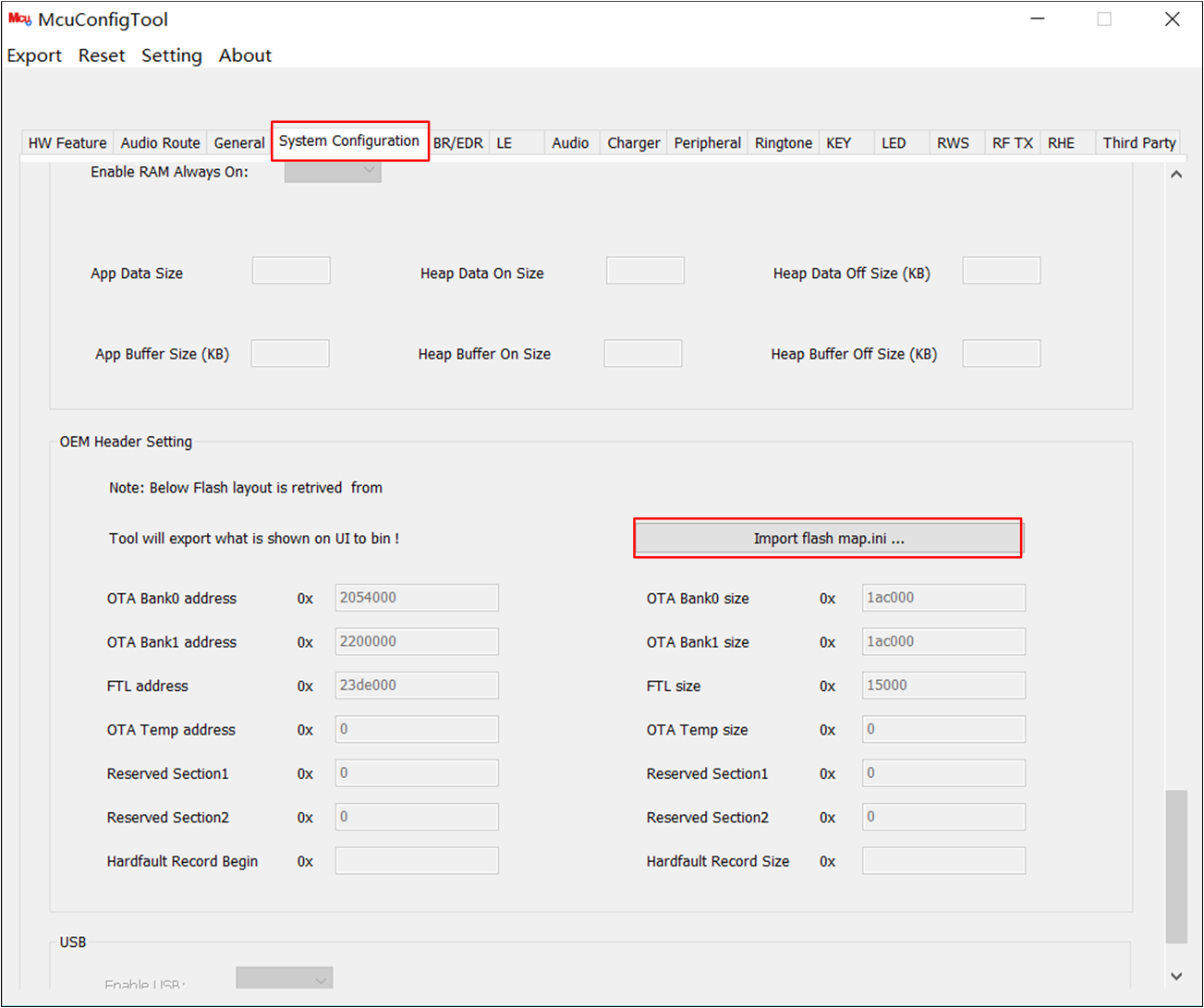
Change Flash Map in SYS CFG
Update OTA Header Image
If the image layout in the bank is changed, the OTA Header should be updated through MPPG Tool.
Open MPPG Tool:
Click the .
Click the Load Flash Layout... to load the new
flash_map.ini.Select Bank0 or Bank1.
Set the OTA image version. The OTA image version is used for bank switch.
Set the RSA key through the Load RSA Key....
Click the Generate... to generate the OTA Header with the new Flash layout.
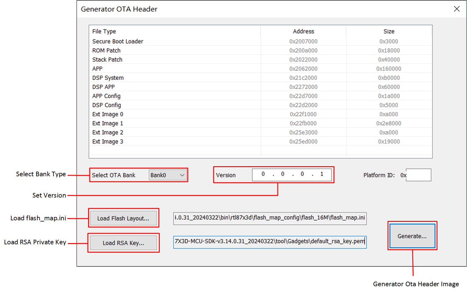
Change Flash Map in OTA Header
Update Image Content by Flash Map
All FSBL/System Patch/Stack Patch images are compiled with position independent attribute in the SDK package. With this user guide, the image content can be updated by the tool update_images_by_flash_map.exe with the new Flash map without recompiling.
It's suggested to copy related files into a new work directory:
Collect the images adjusted by Flash layout according to bank. If there's only one bank, take the bank type as Bank0.
Copy
update_images_by_flash_map.exeunder thesdk\tool\Gadgets\update_images_by_flash_mapto the new work directory.If the images need to be signed by the RSA private key on the secure device, copy the RSA private key to the new work directory. The RSA signature can be updated by the tool
update_images_by_flash_map.exe. Of course, all images can be updated with the RSA signature by the resign tool undersdk\tool\Gadgets\resign_tool.
Run the command to update the images by bank, specify the bank type by --bank_type 0 or --bank_type 1, specify the out directory through -o out_directory_path and specify the new flash_map.ini by --flash_map_ini. Use -d update_images_path to update the images under the directory of update_images_path, and use -f update_image_path to update the specified image file.
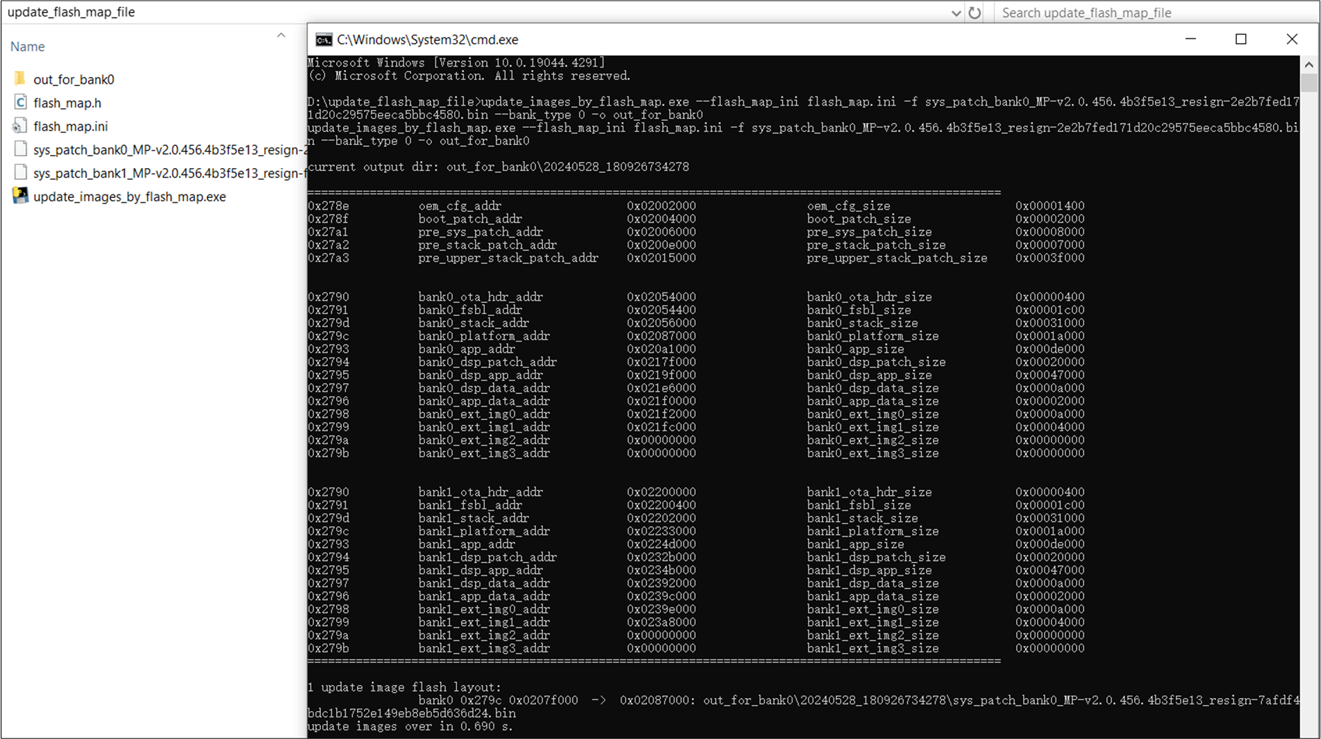
Take Bank0 Images as an example, update image content for Bank0 Images with new flash_map.ini by the following command line:
-
Update images in Bank0 Images under the directory.
update_images_by_flash_map.exe --flash_map_ini NEW_FLASH_MAP_INI_PATH -d UPDATE_IMG_DIR_FOR_BANK0 --bank_type 0 -o OUT_DIRECTORY
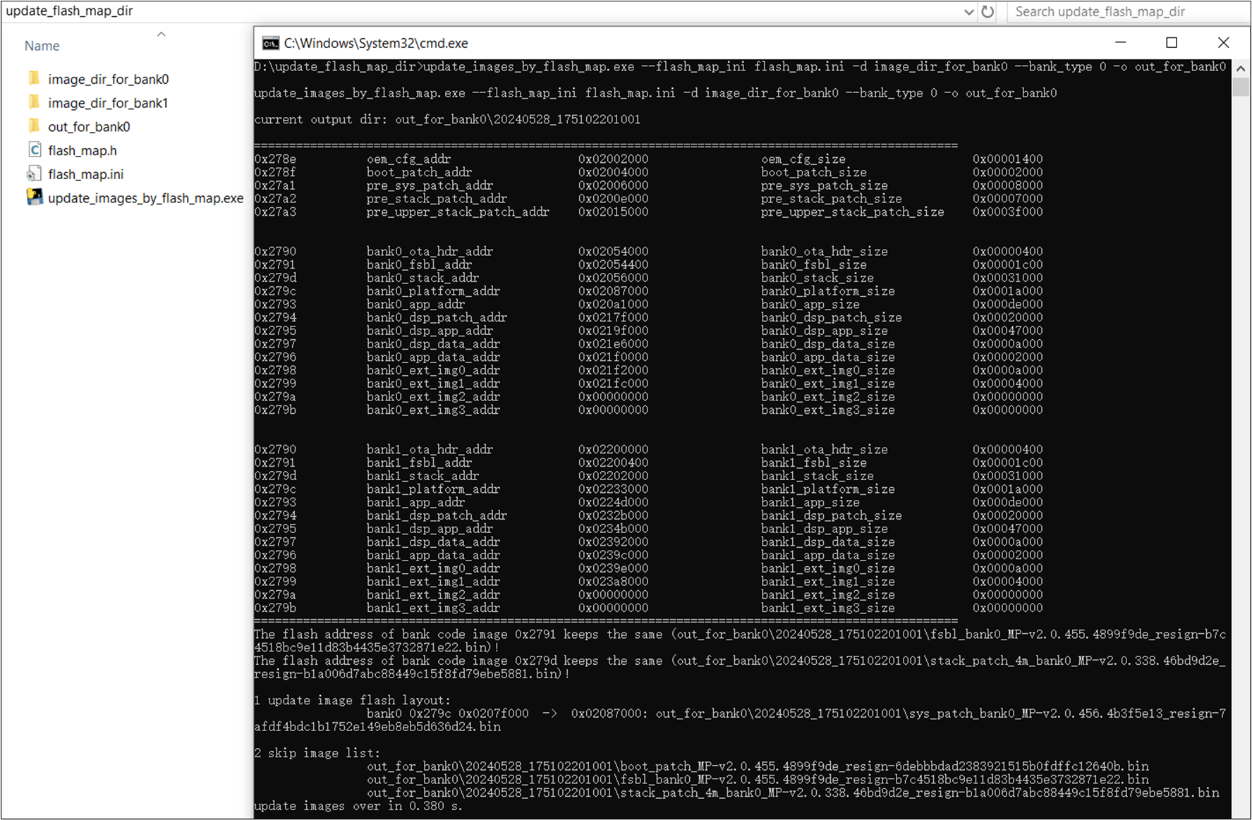
Update Images by Flash Map in Bank0 Images
-
Update the specified single image in Bank0 Images.
update_images_by_flash_map.exe --flash_map_ini NEW_FLASH_MAP_INI_PATH -f UPDATE_IMG_FILE_PATH --bank_type 0 -o OUT_DIRECTORY
Update Single Image by Flash Map in Bank0 Images
For Bank1 Images, use --bank_type 1 in the command line:
-
Update images in Bank1 Images under the directory.
update_images_by_flash_map.exe --flash_map_ini NEW_FLASH_MAP_INI_PATH -d UPDATE_IMG_DIR_FOR_BANK1 --bank_type 1 -o OUT_DIRECTORY
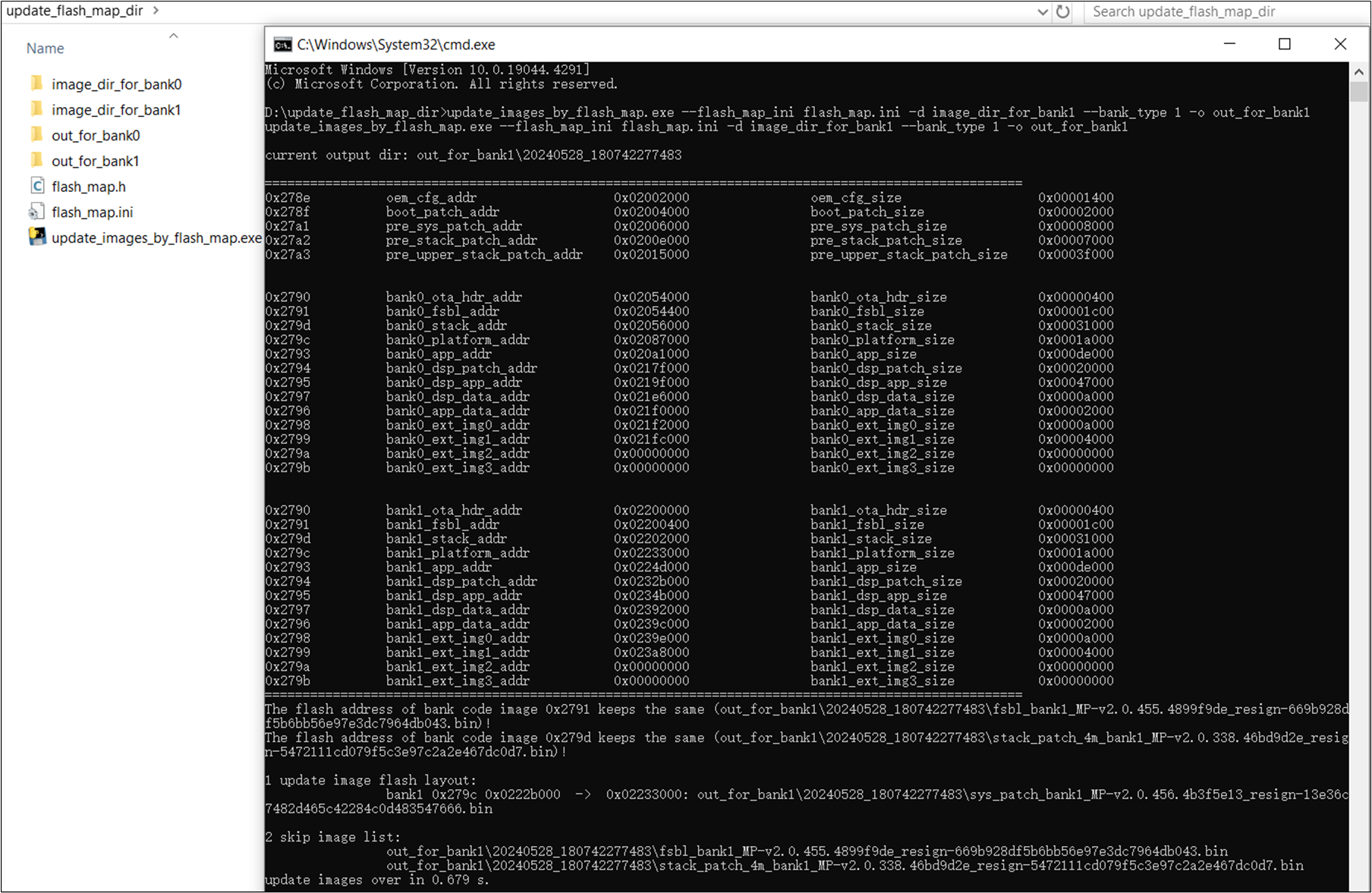
Update Images by Flash Map in Bank1 Images
-
Update the specified single image in Bank1 Images.
update_images_by_flash_map.exe --flash_map_ini NEW_FLASH_MAP_INI_PATH -f UPDATE_IMG_FILE_PATH --bank_type 1 -o OUT_DIRECTORY
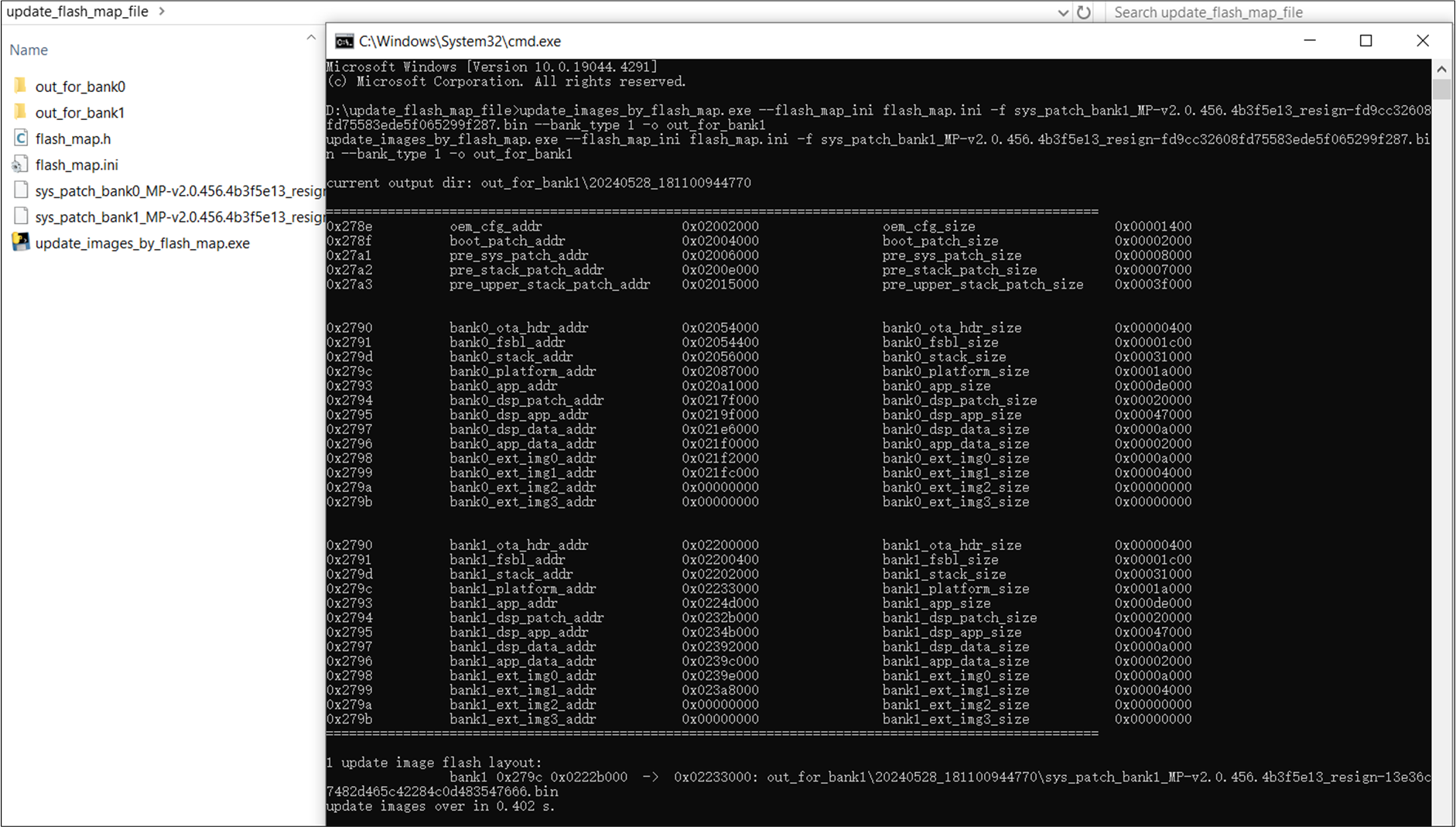
Update Single Image by Flash Map in Bank1 Images
Recompile APP Image
If the image layout for the APP is changed, the APP image should be recompiled:
Copy the new
flash_map.handflash_map.initosdk\bin\flash_map_configto replace the old ones.Recompile the APP project to generate an APP image with the new Flash layout.
Download Images with New Flash Layout
The Flash layout modification would take effect after downloading the images into Flash using MPPG Tool with new flash_map.ini. Please pay attention to the flash_map.ini setting and BANK type setting on the UI. For a secure device, please pay attention to the image resign operation.
Generate EXT Image Command Line
The prepend_header.exe and md5.exe under sdk\tool\Gadgets will be used.
-
Use
prepend_header.exeto add the Image Header for EXT Image Payload. The output file name is the same as the input file name.EXT Image0:
prepend_header.exe /ext_image0 ext_image0.bin /ic_type IC_TYPE
EXT Image1:
prepend_header.exe /ext_image1 ext_image1.bin /ic_type IC_TYPE
EXT Image2:
prepend_header.exe /ext_image2 ext_image2.bin /ic_type IC_TYPE
EXT Image3:
prepend_header.exe /ext_image3 ext_image3.bin /ic_type IC_TYPE
For RTL87x3E, use
/ic_type 87x3E. For RTL87x3EP, use/ic_type 8773E. For RTL87x3D, use/ic_type 87x3D. -
Add MP Header for ext image through
mp.ini. The output file name will append_MPafter the input file name.; This is a configuration file mp.ini used by prepend_header tool to generate MP Header for a given image. ; ; The following sections are mandatory: BinID, Version, PartNumber. ; ; Note that MP Header is a 512-byte fixed data area, pay attention to the long strings that have ; been written and ensure they are not out of bounds of the Header. [MandatoryInfo] ; Image type of current binary file. BinID=ID_EXT_IMAGE1 ; Version of current binary file. Range: 0.0.0.0 ~ 255.255.255.255 Version=1.0.0.0 ; Part number of current image, ASCII type, 32 bytes maximum. PartNumber=RTL87x3E [OptionalInfo] ; Optional. Fill the required version number in specific field if specific image is needed. ; Item will be ignored if the format of the value is wrong or the value does not exist. DependOnSocvConfig = DependOnOemConfig = DependOnFactoryMp = DependOnFsbl = DependOnOtaHeader = DependOnPatch = DependOnApp = DependOnAppData = DependOnAppDataTone = DependOnAppDataVp = DependOnAppDspParam = DependOnDspSys = DependOnDspPatch = DependOnDspScenario1 = DependOnDspScenario2 = ; Optional ASCII type comment string, 255 bytes maximum. Comment= ; Optional ASCII type author information string, 255 bytes maximum. Author= ; Optional ASCII type date and time string, 255 bytes maximum. Date= ; Optional bin Header format revision. Revision=0x01
BinID for EXT image in the
mp.iniis defined as follows, please set the BinID according to the image type.BinID for EXT Image EXT Image Type
BinID
EXT Image0
ID_EXT_IMAGE0
EXT Image1
ID_EXT_IMAGE1
EXT Image2
ID_EXT_IMAGE2
EXT Image3
ID_EXT_IMAGE3
Add MP Header command lines:
EXT Image0:
prepend_header.exe /ext_image0 ext_image0.bin /mp_ini mp_ext_img0.ini /ic_type IC_TYPE
EXT Image1:
prepend_header.exe /ext_image1 ext_image1.bin /mp_ini mp_ext_img1.ini /ic_type IC_TYPE
EXT Image2:
prepend_header.exe /ext_image2 ext_image2.bin /mp_ini mp_ext_img2.ini /ic_type IC_TYPE
EXT Image3:
prepend_header.exe /ext_image3 ext_image3.bin /mp_ini mp_ext_img3.ini /ic_type IC_TYPE
-
Add MD5 data in the image file name.
md5.exe ext_imageN_MP.bin
Generate User Data Image Command Line
The steps to generate these images are as following:
-
Use
prepend_header.exeto add the image header. The output file name is the same as the input file name.prepend_header.exe /user_dataX user_dataX.bin /ic_type IC_TYPE
/user_data1~/user_data8are supported. For RTL87x3E, use/ic_type 87x3E. For RTL87x3EP, use/ic_type 8773E. -
Add MP header for user data image through
mp.ini. The output file name will append_MPafter the input file name.; This is a configuration file mp.ini used by prepend_header tool to generate MP Header for a given image. ; ; The following sections are mandatory: BinID, Version, PartNumber. ; ; Note that MP Header is a 512-byte fixed data area, pay attention to the long strings that have ; been written and ensure they are not out of bounds of the Header. [MandatoryInfo] ; Image type of current binary file. BinID=IMG_USER_DATA1 ; Version of current binary file. Range: 0.0.0.0 ~ 255.255.255.255 Version=1.0.0.0 ; Part number of current image, ASCII type, 32 bytes maximum. PartNumber=RTL87x3E [OptionalInfo] ; Optional. Fill the required version number in specific field if specific image is needed. ; Item will be ignored if the format of the value is wrong or the value does not exist. DependOnSocvConfig = DependOnOemConfig = DependOnFactoryMp = DependOnFsbl = DependOnOtaHeader = DependOnPatch = DependOnApp = DependOnAppData = DependOnAppDataTone = DependOnAppDataVp = DependOnAppDspParam = DependOnDspSys = DependOnDspPatch = DependOnDspScenario1 = DependOnDspScenario2 = ; Optional ASCII type comment string, 255 bytes maximum. Comment= ; Optional ASCII type author information string, 255 bytes maximum. Author= ; Optional ASCII type date and time string, 255 bytes maximum. Date= ; Optional bin Header format revision. Revision=0x01
BinID for user data image in the
mp.iniis defined as follows, please set the BinID according to the image type.BinID for User Data Image User Data Image Type
BinID
User Data Image1
IMG_USER_DATA1
User Data Image2
IMG_USER_DATA2
User Data Image3
IMG_USER_DATA3
User Data Image4
IMG_USER_DATA4
User Data Image5
IMG_USER_DATA5
User Data Image6
IMG_USER_DATA6
User Data Image7
IMG_USER_DATA7
User Data Image8
IMG_USER_DATA8
Add MP header command line:
prepend_header.exe /user_dataX user_data_imageX.bin /mp_ini mp_user_data_imageX.ini /ic_type IC_TYPE
-
Add MD5 data in the image file name.
md5.exe user_data_imageX_MP.bin
Image Data Layout
Each image includes three parts: MP Header, Image Header, and Image Payload. The three parts will be introduced separately later.
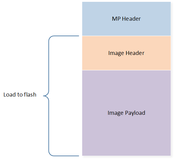
Image Layout
Some configuration data images may exist extended data after the Image Payload, and the extended data length is not included in the image length of MP Header and the Image Payload length of Image Header.
MP Header Layout
The size of MP Header is 512 Bytes on all IC. The information in the MP Header is used by the tools (MPPG Tool and OTA Tool) for performing checks, and it will be stripped by the tools before being downloaded to the MCU .
The data format is as follows:
Type ID |
Data Length |
Data |
|---|---|---|
0x0014 |
0x04 |
Image Size |
Image Header Layout
The Image Header includes information about the image, such as length and secure information. The format of the Image Header for all images on the specified IC is the same. However, some items are useful only in certain images, while they are reserved in others. The default Image Header size varies for different ICs.
RTL87x3E and RTL87x3EP
The default length of the Image Header for RTL87x3E and RTL87x3EP is 1024 bytes. The information in the Image Header Layout is shown in the following map:
Memory Segment |
Size (Bytes) |
Functions |
|---|---|---|
Image_cmac |
16 |
CMAC of the image, for authentication if secure boot is enabled. Note that this field should be all 0xFF when downloading the image file to Flash, and it can be recalculated. |
Image_signature |
256 |
Signature of the image, for authentication if secure boot is enabled. |
Image_hash |
32 |
SHA256 of the image, used to check integrity. |
Image Control Header |
12 |
Includes essential information for this image, see Image Control Header Items for details. |
UUID |
16 |
Should be consistent with ROM UUID. |
Exe Base |
4 |
Image entry address. |
Load Base |
4 |
Start address of code which should be loaded to RAM. |
Load Len |
4 |
Code length of code which should be loaded to RAM. |
Image Base |
4 |
Flash layout of this image. |
Device ID |
2 |
Not used. |
Flash Layout Size |
2 |
Used when Flash size is larger than layout size. |
Decode Key |
16 |
Not used. |
Load Destination Address |
4 |
Specifies the RAM address to copy the image from Flash to RAM. |
Ex_info |
24 |
Used to configure heap range. Only used in APP image. |
Git/Svn Version |
16 |
For image version control. Optional. |
RSA Public Key |
260 |
For image authentication if secure boot is enabled. |
Ver_val |
4 |
OTA Header image version. Only used in OTA Header image. |
Image Info |
128 |
Used to define layout of images in bank. Only used in OTA Header image and Boot Patch Image. See Image Info Items. |
RSVD |
216 |
Reserved for future use. |
RTL87x3D
The default length of the Image Header for RTL87x3D is 4096 bytes. The information in the Image Header Layout is shown in the following map:
Memory Segment |
Size (Bytes) |
Functions |
|---|---|---|
Image_cmac |
16 |
CMAC of the image, for authentication if secure boot is enabled. Note that this field should be all 0xFF when downloading the image file to Flash, and it can be recalculated. |
Image_signature |
256 |
Signature of the image, for authentication if secure boot is enabled. |
Image_hash |
32 |
SHA256 of the image, used to check integrity. |
Image Control Header |
12 |
Includes essential information for this image, see Image Control Header Items for details. |
UUID |
16 |
Should be consistent with ROM UUID. |
Exe Base |
4 |
Image entry address. |
Load Base |
4 |
Start address of code which should be loaded to RAM. |
Load Len |
4 |
Code length of code which should be loaded to RAM. |
Image Base |
4 |
Flash layout of this image. |
Device ID |
2 |
Not used. |
Flash Layout Size |
2 |
Used when Flash size is larger than layout size. |
Decode Key |
16 |
Not used. |
Load Destination Address |
4 |
Specifies the RAM address to copy the image from Flash to RAM. |
Ex_info |
24 |
Used to configure heap range. Only used in APP image. |
Git/Svn Version |
16 |
For image version control. Optional. |
RSA Public Key |
260 |
For image authentication if secure boot is enabled. |
Ver_val |
4 |
OTA Header image version. Only used in OTA Header image. |
Image Info |
128 |
Used to define layout of images in bank. Only used in OTA Header and Boot Patch Image. See Image Info Items. |
RSVD |
216 |
Reserved for future use. |
Dummy Data |
3072 |
Reserved for dummy data. |
Image Control Header Items
The Image Control Header includes basic information about this image. It's in the Image Header. The format is shown in the following figure:
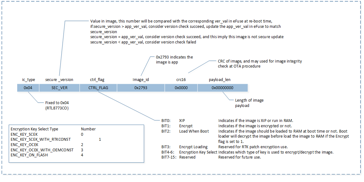
Image Control Header
Note
For System Config Image, two fields of Image Control Header are required and should be filled with the correct data: Image ID and Payload Length.
Image Info Items
The image_info in the Image Header of the OTA Header and Boot Patch Image defines the Flash layout of some images. The format of image_info is different on different IC.
RTL87x3E
The image_info in RTL87x3E is as follows:
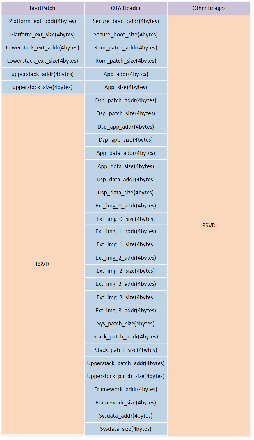
Image Info in RTL87x3E
RTL87x3EP
The image_info in RTL87x3EP is as follows:
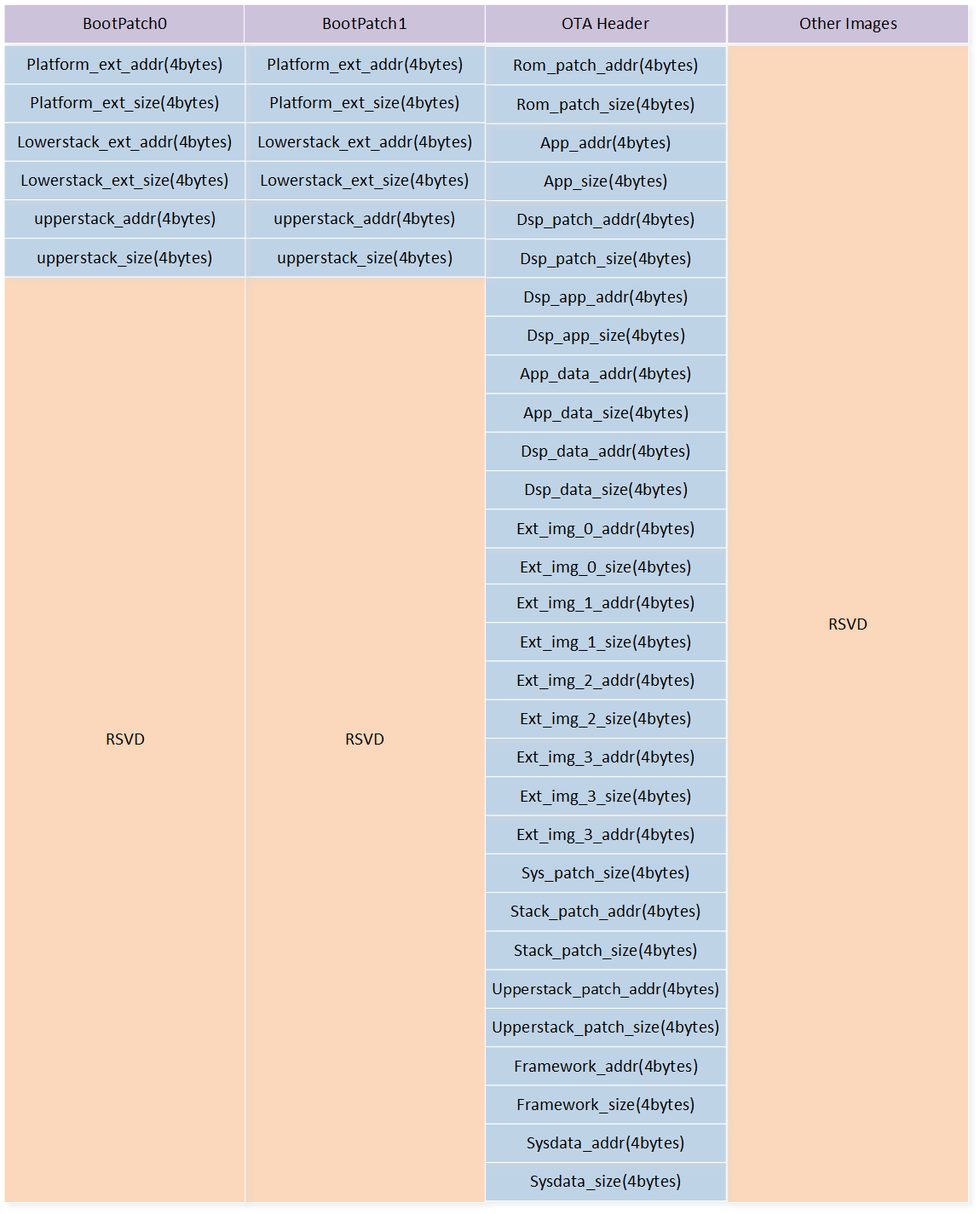
Image Info in RTL87x3EP
RTL87x3D
The image_info in RTL87x3D is as follows:
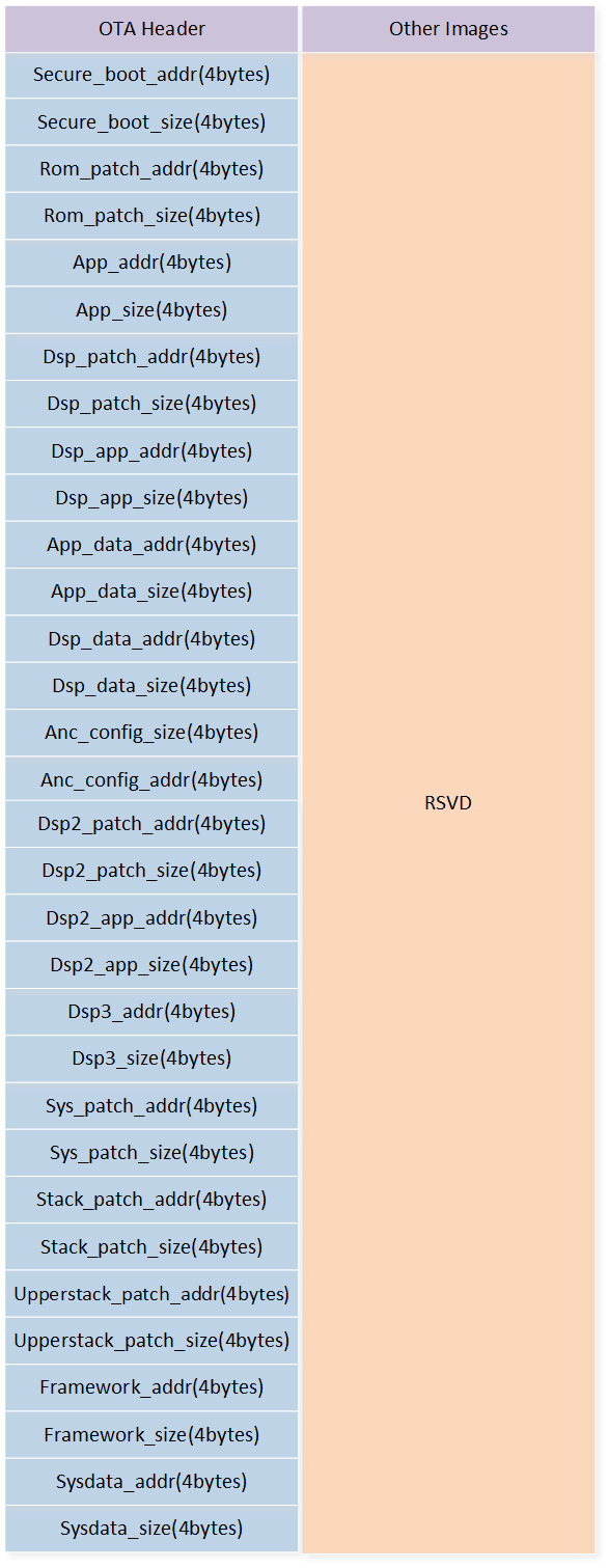
Image Info in RTL87x3D