Platform Overview
The Realtek MCU SDK provides developers with a comprehensive set of software development tools, documentation, and sample projects. These resources enable the development of applications on multiple Realtek Bluetooth audio SoCs, including RTL87x3E and RTL87x3D. The SDK is available as standalone installation packages, optimized for each Realtek Bluetooth audio SoC series. It includes drivers for hardware abstraction layers, peripherals, connectivity (such as Bluetooth/Bluetooth low energy), audio, and other third-party features. Additionally, it offers power and battery management, FOTA capabilities, and FreeRTOS integration. By packaging essential software components and easy-to-use examples in a single software package, the SDK provides developers with a cohesive and consistent software experience.
This document provides a guide for developing Bluetooth audio applications using the RTL87x3 SDK. It covers the following topics:
Getting Started
Simple Introduction to the Hardware Architecture
Detailed Introduction to the Software Architecture
Introduction to Sample Projects
Memory, Power Management, Download and Debug Introduction
Getting Started
The SDK provides example applications for developers to test and verify proper setup on their development kits. After conducting these tests, developers can use these samples as a foundation for developing their own applications.
To start using the SDK, please first familiarize yourself with Quick Start.
Hardware Architecture
This chapter provides developers with a brief description of the hardware architecture. For more detailed information about the hardware, please refer to the HW datasheet.
The hardware block of RTL87x3E is shown in the following figure, and the main features are as follows:
-
Dual-core Processor
Rich Peripherals
Flexible RAM Configuration
Power Management Unit
Clock Management Unit
Dual-mode Bluetooth Radio
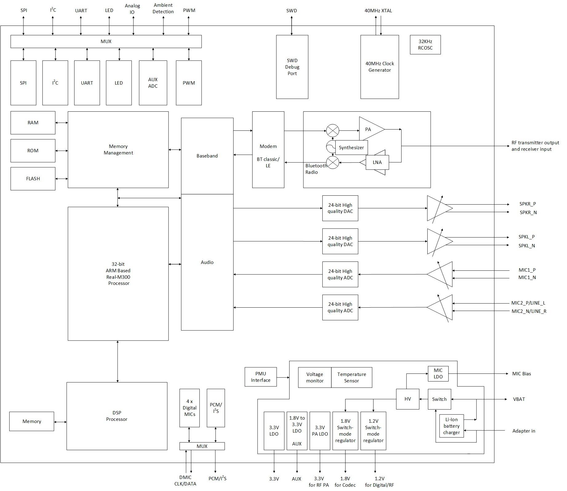
Hardware Block of RTL87x3E
Software Architecture
This section primarily introduces the overall software architecture, including detailed descriptions of various modules.
System Architecture
As shown in the figure below, the system architecture consists of several key components.
GAP: This is the abstraction layer that allows the user application to communicate with the Bluetooth stack. More details can be found in LE Host.
Framework Library: It includes the latest Bluetooth classic protocols/profiles, such as A2DP/HFP, as well as Realtek proprietary protocols.
Audio Subsystem: It provides audio-related functions. Please refer to Audio Subsystem for more details.
LE Audio Library: It includes LE Audio profiles.
DSP SDK: DSP communicates with MCU via IPC. Please refer to the DSP SDK for details on the DSP modules.
IO Drivers: These drivers provide APIs for the user application to interface with Bluetooth audio SoC on-board peripherals without directly accessing registers.
OSIF: It is an abstraction of real-time OS interfaces for the user application.
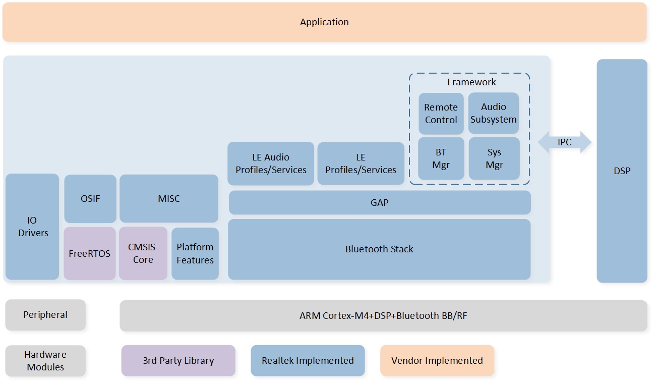
Software Architecture
Operating System
The RTOS is an operating system specifically designed for embedded/real-time applications. Its main goal is to provide a timely and deterministic response to events. These events can be external, such as triggered interrupts, or internal, such as received messages. FreeRTOS is a market-leading RTOS designed for microcontrollers and small microprocessors. It is freely distributed under the MIT open-source license and consists of a kernel and a growing set of IoT libraries that are suitable for various industry sectors. FreeRTOS prioritizes reliability and user-friendliness in its design.
The version of FreeRTOS integrated into the ICs' ROM code is FreeRTOS V8.2.3. It consists of the following components:
Task Management
Queue Management
Interrupt Management
Resource Management
Memory Management
Time Management
The details about FreeRTOS will not be discussed in this context. Please refer to FreeRTOS for more information.
OS Interfaces
This chapter presents the definition of the OS Interface APIs and the reference implementation. It is highly possible to update the specific version of RTOS or even use a different RTOS, which can effectively resolve any compatibility issues associated with specific RTOS interfaces when the OSIF layer is utilized. The OSIF layer, as depicted in the following figure, aims to provide a consistent and standardized set of RTOS APIs by encapsulating the specific RTOS interfaces. By using the OSIF, other software components can be ported OS-independently. Additionally, developers can also provide their own RTOS implementation within the OSIF layer, without requiring any modifications from upper-layer software components.
Therefore, it is highly recommended to use the OSIF API in software development instead of directly accessing specific RTOS interfaces.
The OSIF APIs can be found in the directory sdk\inc\os.
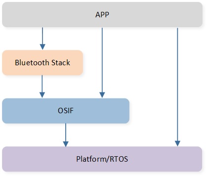
OSIF Overview
Task and Priority
As shown in the following figure, seven tasks have been created for the user application. According to the application requirements, one or more tasks can be created. Setting the priority of the application tasks between 1 and 2 is recommended. The task priority of the application should be lower than the priority of the Bluetooth host.
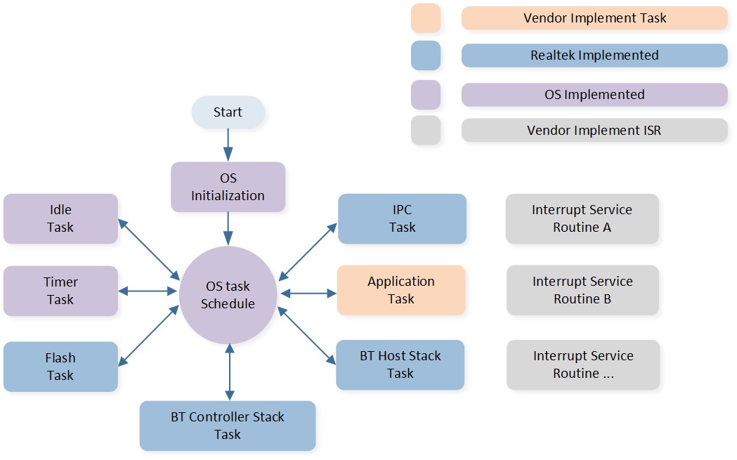
Task Overview
The description of each task and its priority is shown in the following table:
Task |
Description |
Priority |
|---|---|---|
Timer |
Implement the software timer required by FreeRTOS. |
6 |
Bluetooth Controller |
Implement Bluetooth stack protocols below HCI. |
6 |
Bluetooth Host |
Implement Bluetooth stack protocols above HCI. |
3 |
Application |
Handle user application requirements and interact with the stack. |
2 |
Flash |
Handle asynchronous flash requests. |
1 |
Idle |
Run background tasks, including DLPS. |
0 |
IPC |
Process communications between MCU and DSP2. |
2 |
Bluetooth Host SMP |
Process Bluetooth LE pairing. |
1 |
Note
Multiple application tasks can be created, and memory resources will be allocated accordingly.
Idle tasks and timer tasks are provided by FreeRTOS.
Tasks have been configured to be preemptive based on their priority using the SysTick interrupt.
ISRs have been implemented by the supplier.
The IPC task only exists in the RTL87x3D.
Boot Flow
When the system is powered on or reset, the boot flow will be executed. The boot flow includes:
eFuse Validation
Security Control according to the eFuse Value
Flash Image Check and Execute
The eFuse verification determines whether to enable the secure boot. If the secure boot is enabled, image authentication will involve the signature, CMAC, and secure version verification.
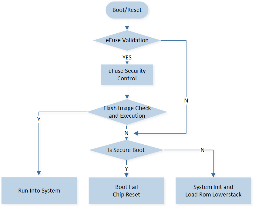
Boot Flow
As shown above, Flash Image Check and Execution means checking all kinds of flash images and executing them. The process includes:
Check boot patch, load and run into boot patch. If single bank OTA is supported in the boot patch, it will check whether there's a valid upgraded image in the flash. If a valid upgraded image exists, a single bank OTA will be done.
Check and load system configuration data (the high-level layout of the flash is included in this file).
Check OTA bank header files and select the bank with the higher version.
Check every flash image in the OTA bank.
Execute the image.
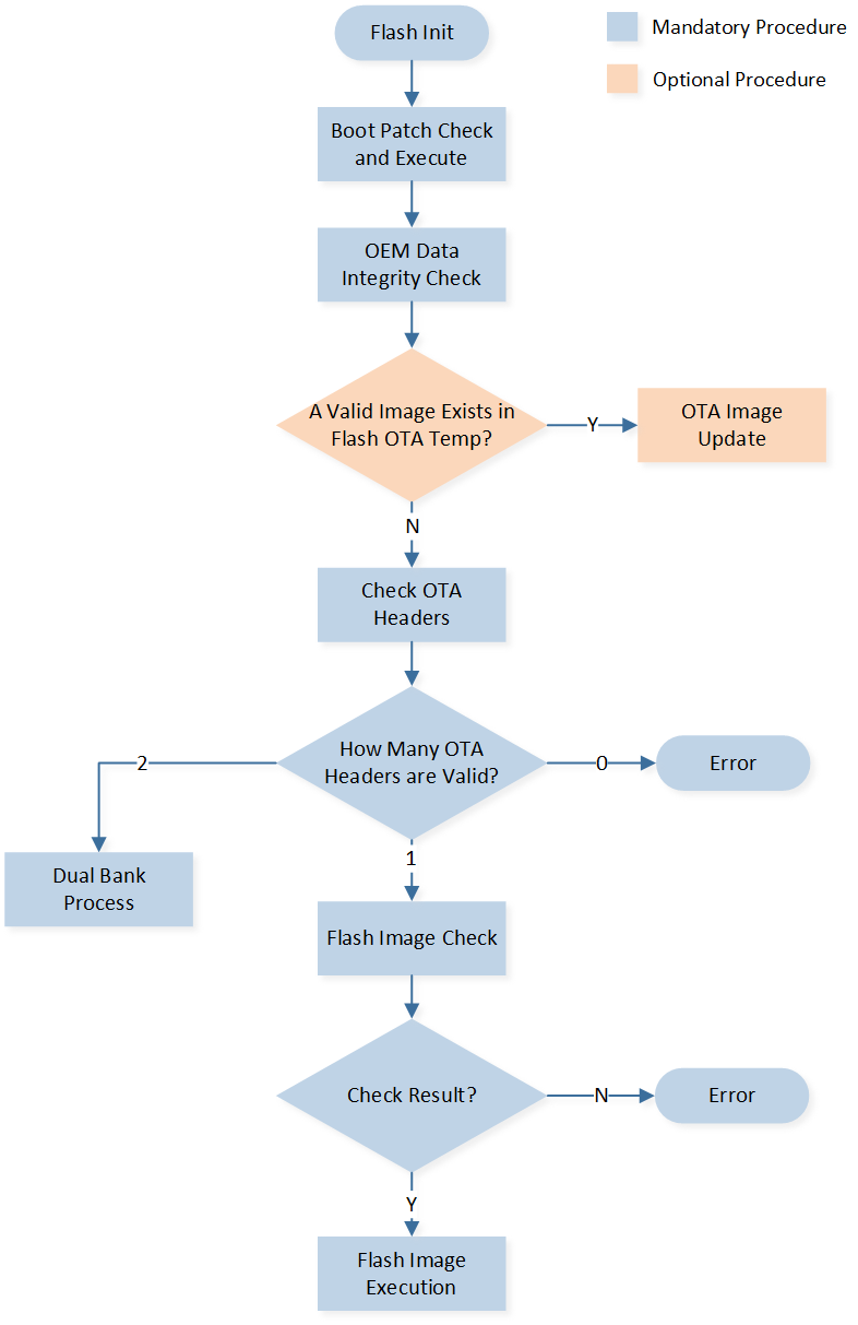
Flash Check and Execution
The Dual Bank Process in the figure above actually executes bank switch to update images. If a new version is updated, images exist in both Bank0 and Bank1 (one bank with the old version, the other bank with the new version). The Dual Bank Process will check the OTA bank with the higher version first, and if the images in the OTA bank are checked successfully, it will continue to be executed. However, if any image in the OTA bank is checked unsuccessfully, the images in the other OTA bank will be checked.
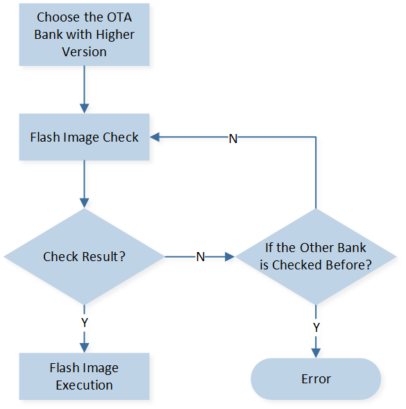
Dual Bank Boot Flow
If you want to learn more about the OTA, refer to OTA.
Application
The SDK provides several example projects that demonstrate features and APIs to help developers become familiar with the SDK. Once developers are familiar with the SDK, they can make customized modifications and develop their own applications.
This chapter contains the following information:
SDK Directory Structure
Sample Projects
Application Process Flow
Message and Event Handling in Application
SDK Directory
The SDK directory is shown in the following figure:
RTL87x3E
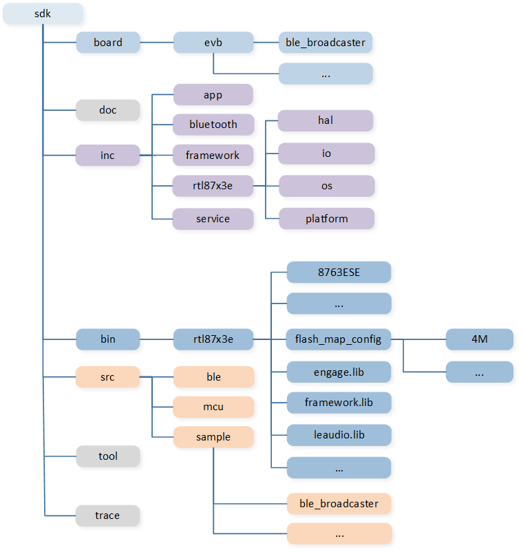
SDK Directory of RTL87x3E
RTL87x3D
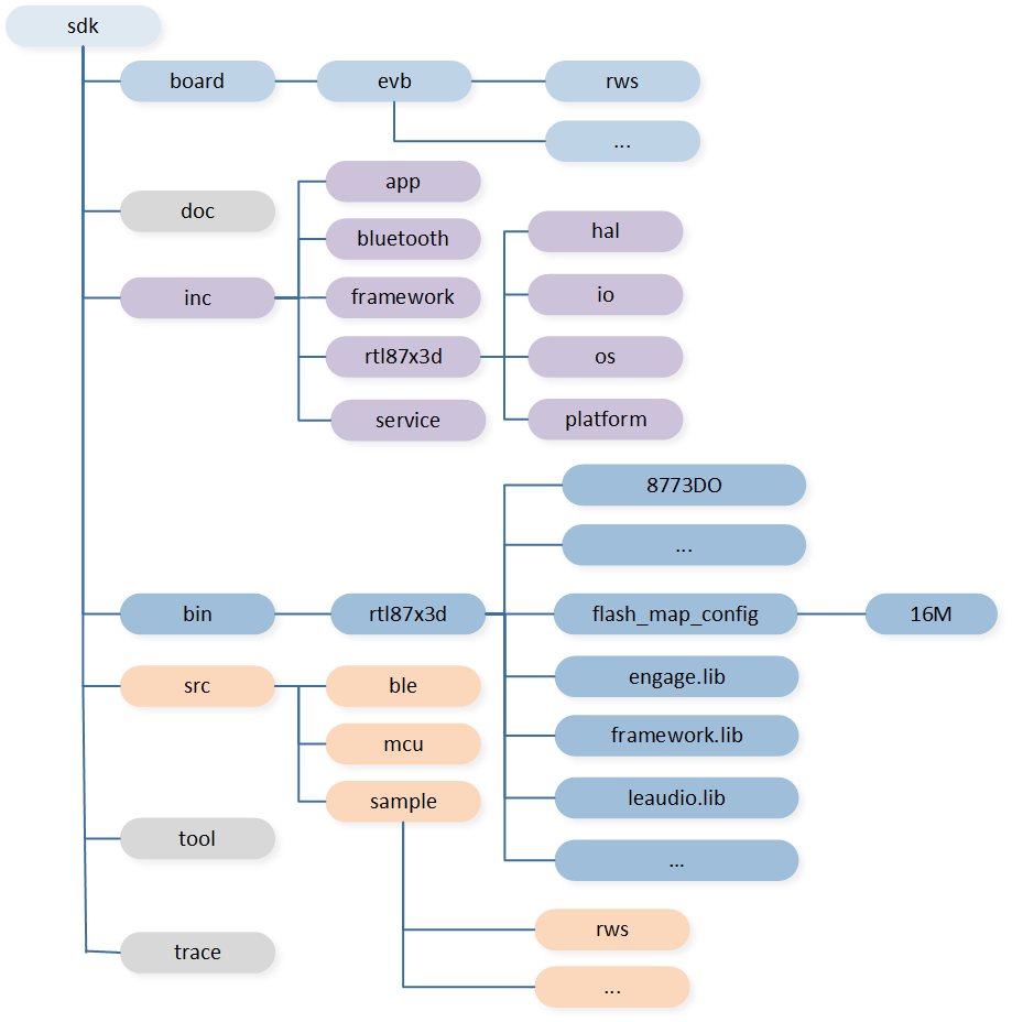
SDK Directory of RTL87x3D
The SDK directory is shown in the figure above, and the description of each directory is shown in the following table.
Directory |
Description |
|---|---|
board |
Sample keil project files that have been well-configured to start with. |
doc |
Contains all the documentation files for the SDK. |
inc |
Header files that provide API definitions exported from ROM. |
bin |
Binary files for users to link their application. |
src |
Source files for sample applications. |
tool |
Host tools set for add-on features. |
trace |
Trace files for default APP binary files provided in the SDK. |
For RTL8773DO, the required DSP images vary based on the development configuration. By default, only HiFi Mini is used, requiring only the default
MCUConfig images from the mcu_cfg directory. However, if developing for HiFi 4, you need to additionally flash the HiFi 4 images and specific
MCUConfig images.
-
For the default configuration with HiFi Mini, flash the default MCUConfig images from the
mcu_cfg\For EVB\defaultdirectory.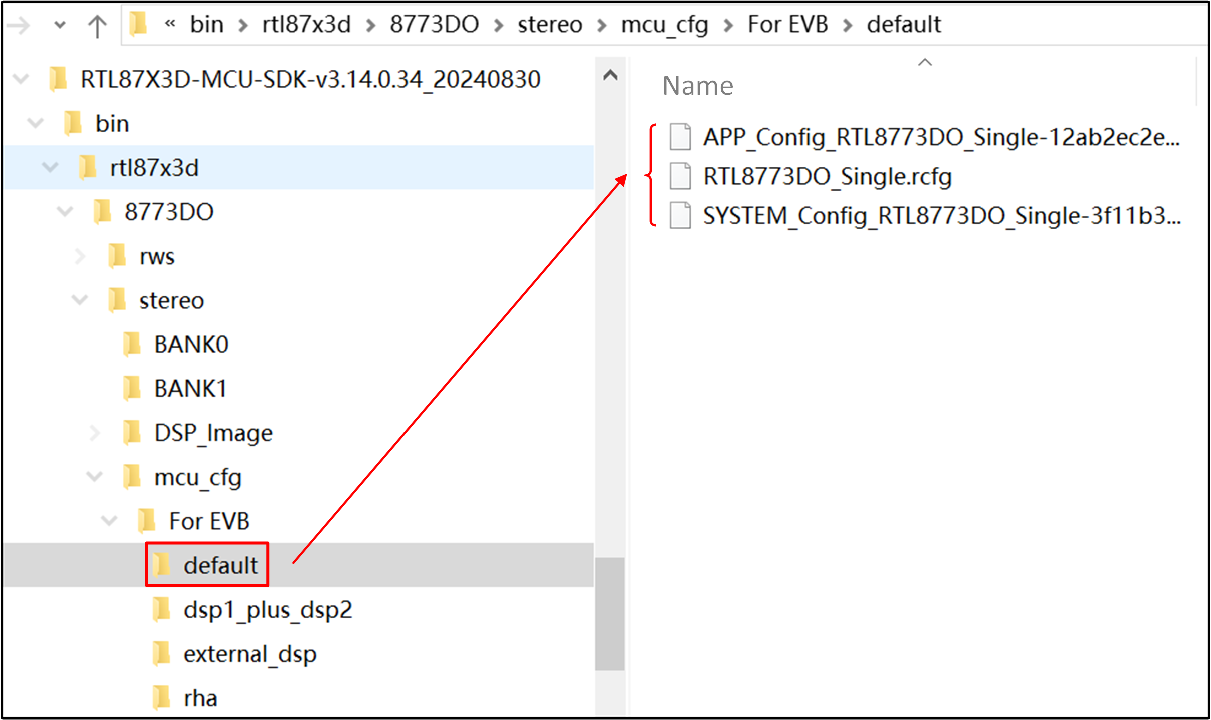
Hifi Mini Flash
-
For HiFi 4 development, flash the MCUConfig images from
mcu_cfg\For EVB\dsp1_plus_dsp2and the images located inDSP_Image\dsp1_plus_dsp2.Please note that during the development of HiFi 4, the HiFi Mini images differ from the default HiFi Mini images. Therefore, the HiFi Mini images need to be replaced with those found in the
DSP_Image\dsp1_plus_dsp2directory.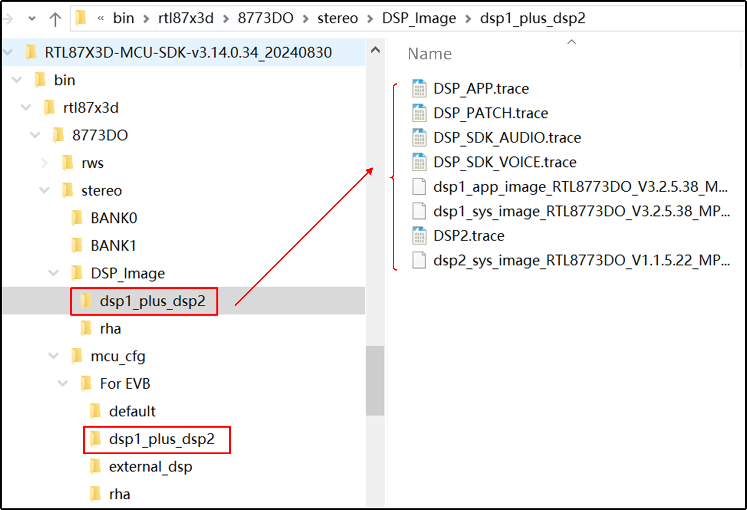
Hifi 4 Flash
Note
The SDK additionally provides application demo binary files. Taking the RTL87x3D as an example, the APP demo for RTL87x3D-MCU-SDK-v3.a.b.c is shown in the following figure.
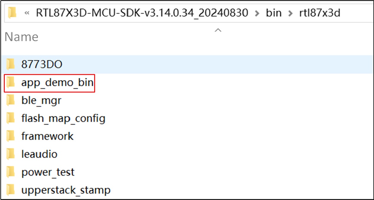
Directory of APP Demo Bin
Sample Projects
To assist in creating user applications, the SDK provides several sample projects to help users get started. These sample projects include the Bluetooth, OTA, IO, etc. Refer to Samples. By studying these sample projects, users can quickly become familiar with the SDK. All sample projects have been configured, and the memory layout in the scatter file has been modified to match the RTL87x3E SoC. Taking the ble_peripheral application as an example, it demonstrates how to initiate the development of a customized user application using the provided sample project. The screenshot given below is obtained with the current version of the SDK and may change in future SDK releases.
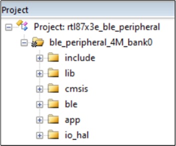
Bluetooth LE Peripheral Project
The source files in the ble_peripheral project are organized into several categories as follows:
The include directory defines the macros necessary for building applications, including exporting the UUID. It should not be modified by any third party.
The lib directory contains all binary symbol files that the application depends on.
The cmsis directory is used for the boot-up code.
The app directory includes the implementation of the ble_peripheral application.
The ble directory includes Bluetooth LE profiles or services that are used by the sample application.
The RTL87x3E APP MCU is based on the ARMCM3 architecture. The LIB and sample APP projects released in the default SDK all use the following devices.
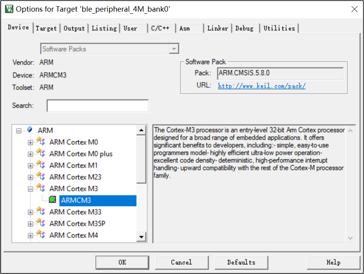
Project Device Selection
The common files in sample applications are explained as follows.
File Name |
Description |
|---|---|
|
UUID header files provided by the SDK to identify the ROM, no change needed. |
|
A ROM symbol library file used by the user application to link any ROM symbols. |
|
An abstraction layer of hardware, which can better ensure the portability of Realtek products. |
|
Assembly file for RTL87x3E application startup. |
|
C file of the RTL87x3 application system. |
|
Flash layout file, which is generated by MPPG Tool. |
|
Memory configuration file. |
The sample project may be upgraded along with the SDK. To better utilize the upgraded sample code, it is recommended to organize and modularize any newly added user code. For further information on each sample project, please refer to its respective user manual.
Application Process Flow
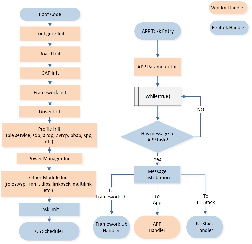
Application Process Flow
The description of each action is shown in the following table.
Action |
Description |
|---|---|
Configuration Init |
Contains initialization of APP and framework configuration. |
Board Init |
Contains initialization of PINMUX settings and pad settings. |
GAP Init |
Contains initialization of GAP-related parameters. |
Driver Init |
Contains initialization of peripherals. |
Profile Init |
Contains initialization of dual mode profiles. |
Power Manager Init |
Contains initialization of power management related. |
Other Modules Init |
Contains initialization of other modules such as roleswap, MMI, DLPS, etc. |
APP Parameter Init |
Contains initialization of user application related. |
The system is initialized in the main() function, including board, peripherals, Bluetooth stack, profile, power mechanism, task, etc.
In the application layer task, the Bluetooth stack, profiles, and peripheral drivers are initialized, and an IO messaging mechanism is implemented.
All functionalities are encapsulated as IO events, which are processed by the corresponding message handlers.
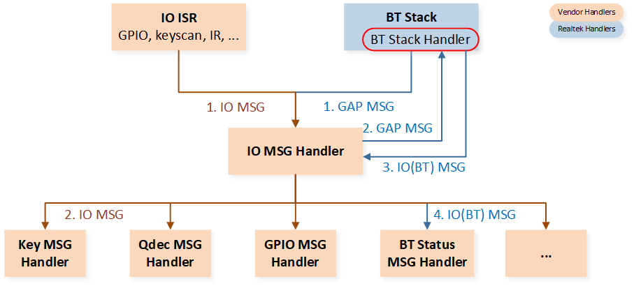
IO Message Handling Flowchart
Message and Event Handling Flow
An original message can be sent from either the universal peripherals' ISR or the Bluetooth stack, and it is processed through the following flow:
The message from peripherals is forwarded by the message distributor to the IO message handler for processing.
The message from the Bluetooth stack is forwarded by the message distributor to the Bluetooth state machine. The Bluetooth state machine handles the message and sends a Bluetooth IO message. The message distributor receives the Bluetooth IO message and then forwards it to the IO message handler for processing.
After receiving a message, the IO message handler makes a judgment and calls the related event handler.
Developers should:
Implement the peripheral ISR and perform initial handling within the ISR. If further handling is required, a message will be sent.
Maintain an IO message handler to receive and handle messages defined by the developer.
Implement an event handler for the application.
The lower layer uses the message and event mechanisms to notify the upper layer, and the upper layer calls the lower layer functions through APIs.
IO Message
The format and message type definition of the IO message are as follows.
Message Format
{
    uint16_t type;
    uint16_t subtype;
    union
    {
        uint32_t  param;
        void     *buf;
    } u;
} T_IO_MSG;
Message Type Definition
typedef enum
{
    IO_MSG_TYPE_BT_STATUS,  /**< bluetooth status change with subtype GAP_MSG_TYPE */
    IO_MSG_TYPE_KEYSCAN,    /**< Key scan message with subtype T_IO_MSG_KEYSCAN */
    IO_MSG_TYPE_QDECODE,    /**< Subtype to be defined */
    IO_MSG_TYPE_UART,       /**< UART message with subtype T_IO_MSG_UART */
    ...

} T_IO_MSG_TYPE;
Message Subtype Definition
Taking the subtype of UART as an example, developers have the ability to define their own subtypes for UART.
typedef enum
{
    IO_MSG_UART_RX              = 0x10, /**< UART RX event */
    IO_MSG_UART_TX              = 0x20, /**< UART TX event */
} T_IO_MSG_UART;
Define User Message
Developers can flexibly expand message types and customize message subtypes as needed.
Power Manager Settings
Developers can enable DLPS using the APIs below, and the code is controlled by the F_DLPS_EN flag defined in app_peripheral_flags.h.
void pwr_mgr_init(void)
{
#if F_DLPS_EN
    bt_power_mode_set(BTPOWER_DEEP_SLEEP);
    power_mode_set(POWER_DLPS_MODE);
#endif
}
Please refer to Low Power Mode for more details.
Memory
This section introduces the memory system. IC's memory system consists of ROM, RAM, Flash, and eFuse, all of which has a flexible configuration mechanism.
Memory Map
The global size and the heap memory size can be adjusted by modifying the APP_GLOBAL_SIZE in mem_config.h.
The total size of heap and global is fixed and cannot be changed. Increasing the global size will decrease the heap size, and vice versa. Users can adjust APP_GLOBAL_SIZE as needed.
#define APP_GLOBAL_SIZE (22*1024)
Please refer to Memory Hierarchy for RTL87x3E for more details.
Flash APIs
Flash operation APIs are listed as follows.
bool fmc_flash_nor_read(uint32_t addr, void *data, uint32_t len);
bool fmc_flash_nor_auto_dma_read(uint32_t src, uint32_t dst, uint32_t len, FMC_FLASH_NOR_ASYNC_CB cb);
bool fmc_flash_nor_write(uint32_t addr, void *data, uint32_t len);
bool fmc_flash_nor_erase(uint32_t addr, FMC_FLASH_NOR_ERASE_MODE mode);
Please refer to Flash for more details.
FTL
FTL is used as an abstraction layer for the Bluetooth stack and the user application to read and write data in flash. Refer to Flash for details.
eFuse
eFuse is a block of one-time programming memory, which is used to store important and fixed information, such as the UUID, security key, and other one-time programming configurations. The single bit of eFuse cannot be changed from 0 to 1, and there is no erase operation in eFuse, so be careful when updating eFuse. Realtek offers MPPG Tool to update certain eFuse sections.
Note
Most of the eFuse content has already been used internally by RTK. If customers need to use the eFuse content, they should confirm with RTK which specific sections of the IC are available.
Interrupt
This section specifies the nested vectored interrupt controller rules and interrupt priority.
Nested Vectored Interrupt Controller
NVIC features are as follows.
Several exceptions and maskable interrupt channels.
Programmable priority levels.
Support vector table relocation.
Low-latency exception and interrupt handling.
Implementation of system control registers.
The NVIC and the processor core interface are closely coupled, enabling low-latency interrupt processing and efficient handling of late-arriving interrupts. All interrupts, including the core exceptions, are managed by the NVIC.
The interrupt vector table is used to manage and handle different types of interrupts. It is a data structure stored in memory that contains the entry addresses of interrupt handler routines. The advantage of the interrupt vector table mechanism is its ability to handle different types of interrupts flexibly. By storing the entry addresses of the interrupt handler routines in the interrupt vector table, the system can quickly locate and call the relevant routine based on the interrupt type, improving system responsiveness and efficiency.
All ICs can update the interrupt vector table by RamVectorTableUpdate API.
Interrupt Priority
The ICs support three fixed highest-priority levels and several levels of programmable priority. The priority number is below.
-3 > -2 > -1 > 0 > 1 > 2 > 3 > 4 > 5 > 6 > 7
Priority |
Usage |
|---|---|
-3 |
Reset Handler |
-2 |
NMI |
-1 |
Hard Fault |
0~1 |
It is used for interrupts with very high real-time requirements. (Note: Interrupts of this priority will not be masked by the critical section of FreeRTOS, but the interrupt handler cannot call any FreeRTOS API.) |
2~6 |
Normal ISR |
7 |
SysTick and PendSV |
Power Management
When certain conditions are met, the ICs will enter DLPS mode and will be woken up when they need to work normally. Please refer to Low Power Mode for more details.
Download
Please refer to Required Files in Quick Start and Realtek Bluetooth MP Tool in Tool Set for more details.
Debug
Please refer to Debug Methods for more details.