Low Power Mode
Low power mode: It involves putting the device into a low power state when it is not in use. In this state, the device consumes less power but can quickly wake up and resume full functionality when needed. Most components such as Clock, CPU, Peripherals, and RAM can be powered off to reduce system power consumption. For example, DLPS is one kind of low power mode.
This article will introduce different low power modes, power manager, how to add low power mode support in an application, and DLPS troubleshooting.
Power Mode Brief Introduction
For all IC that support two power units, both the System platform and Bluetooth MAC can enter low power mode. The two units are inherent in the hardware power architecture. System platform supports five power modes: ship, power down, DLPS, LPS, and active mode. And Bluetooth MAC supports two power modes: deep sleep mode and active mode.
System Power Domain Introduction
The system has four types of power domains, which are listed as: Core domain, PON domain, AON domain, DPD domain.
DPD domain is the most fundamental power domain of the system, and it is active when the system is turned on. It contains the necessary modules to bring the system out of low power mode.
AON domain provides the power for AON Finite State Machine to control the clocks and power trails.
PON domain supplies power to SRAM, some hardware modules for retention, and the Bluetooth MAC when it is in DLPS mode.
Core domain supplies power for CPU and peripheral digital circuits.
The following table lists the peripheral power domain of RTL87x3E.
Peripheral |
Core Domain |
PON Domain |
AON Domain |
|---|---|---|---|
O |
|||
O |
|||
O |
|||
O |
|||
O |
|||
O |
|||
O |
|||
O |
|||
O |
|||
O |
|||
O |
|||
O |
|||
O |
|||
O |
The following table lists the peripheral power domain of RTL87x3D.
Peripheral |
Core Domain |
PON Domain |
AON Domain |
|---|---|---|---|
GDMA |
O |
||
GPIO |
O |
||
I2C |
O |
||
IR |
O |
||
KeyScan |
O |
||
QDEC |
O |
||
ADC |
O |
||
SLEEP LED |
O |
||
RTC |
O |
||
SPI |
O |
||
TIM/PWM |
O |
||
UART |
O |
||
I2S |
O |
The following table lists the peripheral power domain of RTL87x3EP.
Peripheral |
Core Domain |
PON Domain |
AON Domain |
|---|---|---|---|
GDMA |
O |
||
GPIO |
O |
||
I2C |
O |
||
IR |
O |
||
O |
|||
QDEC |
O |
||
ADC |
O |
||
RTC |
O |
||
SPI |
O |
||
TIM/PWM |
O |
||
UART |
O |
||
I2S |
O |
Platform Low Power Mode
This section introduces the low power mode related to platform.
Power Mode
The following table provides an overview of the usage of different power domains in various power modes.
Power Domain |
Usage |
Active |
DLPS |
Power Down |
Ship |
|---|---|---|---|---|---|
Core Domain |
CPU |
O |
X |
X |
X |
Peripheral |
|||||
PON Domain |
Bluetooth MAC |
O |
O |
X |
X |
Retention |
|||||
AON Domain |
AON Register |
O |
O |
O |
X |
RTC |
|||||
PAD |
|||||
DPD Domain |
Adapter |
O |
O |
O |
O |
The platform supports the following power modes, sorted by power consumption.
-
Active Mode
All power domains are on.
The system is running.
-
DLPS Mode
DPD domain, AON domain, PON domain are powered on. Core domain is powered off.
SRAM and part of the hardware register can be retained automatically.
The restore process will run when the system wakes up from DLPS mode, and recovery time will be quicker than when the system reboots.
In DLPS mode, the system can be woken up by OS scheduler (software timer/delay task), Bluetooth MAC, RTC, PAD, MFB, adapter, CapTouch, etc.
-
Power Down Mode
DPD domain and AON domain are powered on. PON and Core domain are powered off.
SRAM will be powered off. Hardware settings could not be backed up.
The system will perform the reboot flow when woken up from power down mode. The wake-up time is longer than DLPS mode.
In power down mode, the system can be woken up by PAD, MFB, adapter, RTC, CapTouch.
-
Ship Mode
AON domain will be reset to default value in ship mode, such as CPU clock source/frequency.
It will take some time to recover from ship mode as it will perform the whole reboot flow.
In ship mode, the system can only be woken up by MFB and adapter.
Features
The system will only enter DLPS/power down/ship mode when Bluetooth MAC is in deep sleep mode.
Low power mode needs to be turned off while using Keil for online debugging because turning off the CPU will cause the SWD to disconnect.
For RTL87x3E and RTL87x3EP, in order to wake the system up from DLPS mode, the duration of the PAD/MFB/adapter wake-up pulse must be longer than 2T of AON clock. The clock source of AON clock can be selected in MCUConfig Tool.
For RTL87x3E and RTL87x3EP, in order to wake the system up from power down mode, the duration of the PAD/MFB/adapter wake-up pulse must be longer than 2T of AON clock when the 32K of AON clock is on in power down mode. For more details about AON clock selecting, refer to Select AON Clock.
For RTL87x3E and RTL87x3EP, when the 32K of AON clock is turned off in power down mode, the system can be woken up by a short pulse.
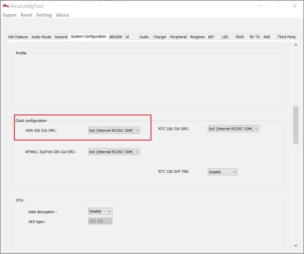
Select AON Clock
The times listed in the following table for entering and exiting low power mode.
IC |
Flow |
Ship |
Power Down |
DLPS |
|---|---|---|---|---|
RTL87x3E |
Enter (ms) |
< 110 |
< 1 |
< 5 |
Exit (ms) |
< 420 |
< 350 |
< 7.2 |
|
RTL87x3D |
Enter (ms) |
< 3 |
< 3 |
< 6.5 |
Exit (ms) |
< 780 |
< 440 |
< 4.3 |
|
RTL87x3EP |
Enter (ms) |
< 110 |
< 1.5 |
< 6 |
Exit (ms) |
< 600 |
< 510 |
< 6 |
Note
The wake-up time is a bit long for RTL87x3D and may affect the limit of wake-up time.
Bluetooth MAC Low Power Mode
This section introduces the low power mode related to Bluetooth MAC.
Power Mode
Bluetooth MAC supports the following power modes, sorted by power consumption.
-
Active Mode
Bluetooth MAC working functionally, all the registers can be accessed. The clock source is 10MHz.
-
Deep Sleep Mode
Low power saving mode.
Bluetooth MAC is working with clock source 32KHz.
Most of the registers cannot be accessed.
Features
Support Bluetooth to enter/exit deep sleep mode when system is in active state.
Power Manager Introduction
Most of the time, the system is in an idle state and only necessary data needs to be retained for system recovery. Components such as the clock, CPU, peripherals, and RAM can be powered off to reduce system power consumption. When there are any events to be handled, the system will exit from low power mode. The clock, CPU, Bluetooth, peripherals, and RAM will be re-powered on and recovered to the previous state before entering DLPS, and then respond to the wake-up event. The power manager operates hardware modules at different system levels. Each system level contains a different power manager unit. Each power manager unit should implement the check/store/enter/exit/restore functions. This section describes the power manager in detail.
Enter Low Power Mode
This section introduces the flow and conditions for entering low power mode.
DLPS Mode Entry Flow
DLPS mode entry flow is shown below.
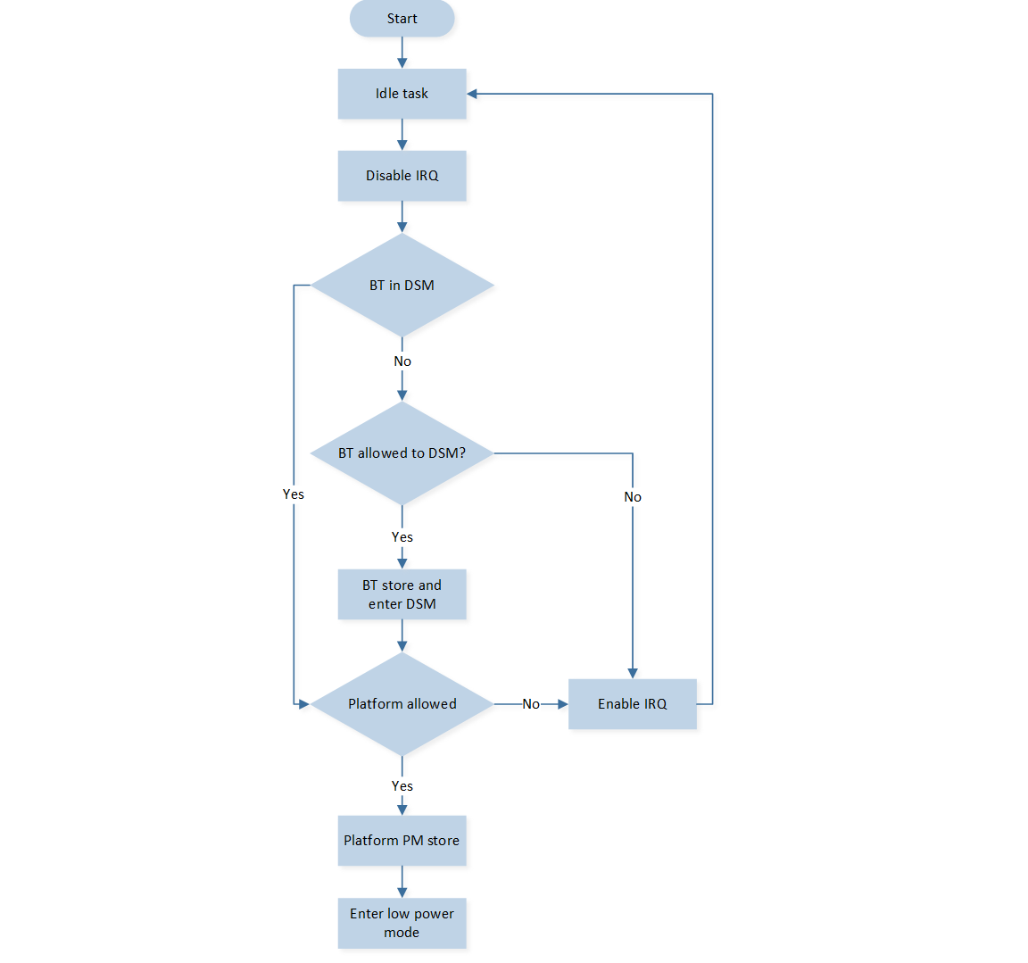
Low Power Mone Enter Flow
Disable Interrupt
-
Enter Check
Inquire each module whether it is allowed to enter the low power mode. If a module needs to be inquired before entering the low power mode, it should first register a callback function to the power manager. When the power manager calls the callback functions, each module will inform the power manager whether it is allowed to enter the low power mode based on its own condition. The low power mode is unavailable unless all modules allow entering low power mode.
Inquire each Queue whether there is any data to be handled. If there is any data, the system will not enter DLPS.
-
Store Peripheral Registers
When entering DLPS, the system automatically performs peripheral storage actions. Additionally, the necessary CPU register storage actions are also implemented in this callback function. More details are described in the application sample.
Enter Low Power Mode
Conditions for System to Enter Low Power Mode
The conditions for entering low power mode.
Conditions for System to Enter DLPS Mode
The system will enter DLPS mode only when all of the following conditions are met.
CPU executes in idle task, when any other tasks are in block or suspend state and no ISR execution exists.
All OS queue messages have been handled.
-
Bluetooth allows entering deep sleep mode.
Bluetooth MAC will enter deep sleep mode when the next wake-up instance is more than 30ms.
-
Bluetooth MAC will only enter deep sleep mode when in one of the following states and corresponding interval is set.
Standby state.
Bluetooth scan state, page scan/inquiry scan interval > 30ms.
Bluetooth sniff mode, sniff interval > 30ms.
Bluetooth Low Energy connection state, connection interval * 1.25ms > 30ms.
Bluetooth Low Energy advertising state, advertising interval * 0.625ms > 30ms.
Bluetooth Low Energy scan state, (scan interval-scan window) * 0.625ms > 30ms.
All the DLPS check callback functions return true, which are registered by the platform, peripherals, and application.
Data, including tasks' stack, that needs to be backed up is not larger than backup space.
Charger is not in a charging state.
There are no high precision system timers in an active state.
The hardware timer is not configured to block DLPS, and the arrival time interval of the hardware timer is longer than 30ms.
The system would perform data and registers backup and IO setting before entering DLPS mode if all entry conditions were satisfied.
Note
Users can configure the hardware timer to block DLPS by calling the API: bool hw_timer_lpm_set(T_HW_TIMER_HANDLE handle, bool enable).
Special Condition for Entering Power Down/Off Mode
The above DLPS entering conditions are met.
There are no active software timers, for the callback functions cannot be called in power down mode.
Note
The error code for being unable to enter power down mode due to software time is PLATFORM_PM_ERROR_WAKEUP_TIME. It is recommended that the customer take the initiative to close the timer started by each module when entering the power down mode. In addition, the customer can close the timer through the API: void power_stop_all_non_excluded_timer(void).
Exit Low Power Mode
This section introduces the flow and conditions for exiting low power mode.
DLPS Exit Flow
DLPS mode exit flow is shown below.
Power and clock should be recovered by the CPU.
The RAM and flash are powered up.
Recover Bluetooth.
Go to the application callback to restore peripherals.
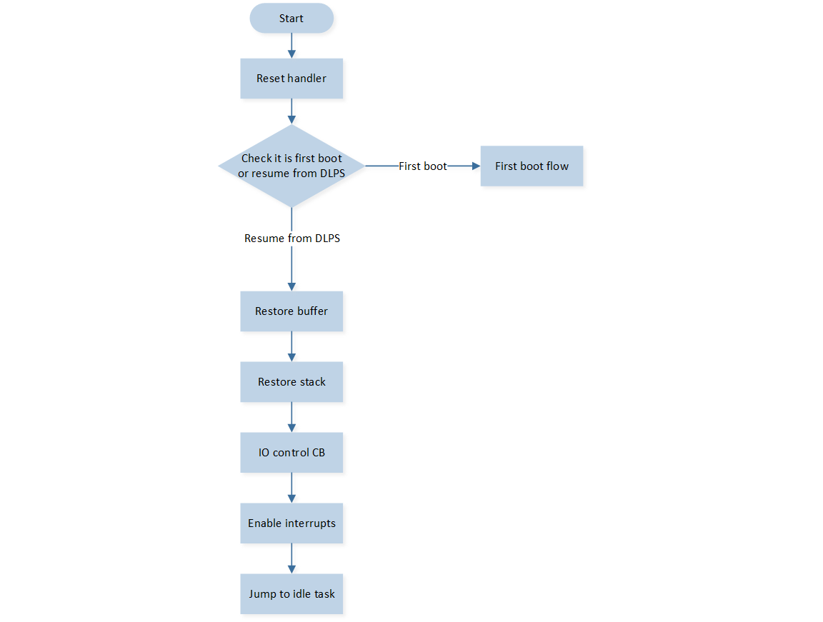
Low Power Mone Exit Flow
-
Reset handler.
In the reset handler, the reset reason will be detected. If the system is power-on, it will perform the first boot flow. If the system exits from DLPS mode, it will perform DLPS recovery flow.
-
Return to idle task.
Configure system tick interrupt.
Recover PSP based on the stack top pointer saved by the idle task (the address upon creation of the idle task).
Enable interrupt.
Jump to the starting location of the idle task to schedule again.
Conditions for Exiting from Low Power Mode
One of the following occurrences would awaken the system, which must be set up before entering DLPS mode.
MFB can be used in DLPS/power down/ship mode, details refer to MFB.
Adapter can be used in DLPS/power down/ship mode, details refer to Adapter.
PAD wakeup signal can be used in DLPS/power down mode, details refer to Use Wakeup Pin.
-
The Bluetooth interrupt can only be used in the following scenarios and can only be used in DLPS mode.
Scan anchor arrives when Bluetooth is in scan state.
Advertising anchor arrives when Bluetooth Low Energy is in advertising state.
Connection event anchor arrives when Bluetooth connection is established.
Any Bluetooth event occurs, such as remote connection request or receiving data.
RTC interrupt can be used in DLPS/power down mode, details refer to RTC Interrupt.
Software timer can be used in DLPS mode, when there are software timer expires and callback function to be called, or when there are delay task expires and need to be active state.
CapTouch can be used in DLPS/power down mode, details refer to CapTouch.
How to Add Low Power Mode Support in Application?
Power manager is a modular and extensible power management architecture. It consists of stages such as check, store, enter, exit, and restore, as well as other operations that are registered to power manager for unified management at the application boot. Users only need to determine whether the current low power mode is suitable based on the application scenario they want to use.
Configure Power Mode
Users can use the listed API to switch the system to different power modes.
void bt_power_mode_set(BtPowerMode mode);
int32_t power_mode_set(POWERMode mode);
These two functions set the current low power mode and are frequently called when an application boots. When the conditions are met in Conditions for System to Enter Low Power Mode, the system will enter low power mode.
Examples:
void app_dlps_init(void)
{
    //...
    bt_power_mode_set(BTPOWER_DEEP_SLEEP);
    if (app_cfg_const.enable_power_off_to_dlps_mode)
    {
        power_mode_set(POWER_DLPS_MODE);
    }
    else
    {
        power_mode_set(POWER_POWERDOWN_MODE);
        //...
    }
}
Register Callback to Power Stage
For the Bluetooth MAC deep sleep mode. The stage is handled in the ROM.
For the platform low power mode. It must be restricted or compatible with OS task functions. Additionally, each low power stage has a function API that is provided to applications for registration. The power manager will call these callback functions when entering and exiting the low power mode. In order to minimize the influence on the time of exiting low power mode, it is recommended to register the function in the platform power manager pend stage after the platform and CPU are ready.
Users can use the listed API to register callbacks to the platform low power stage.
int32_t power_stage_cb_register(POWERStageFunc func, POWERStage stage);
IO store/restore will be automatically performed based on whether the corresponding IO clock is active or not. Users can call the API io_dlps_register() to initialize IO store/restore and do not need to worry about which IO peripheral requires specific handling, except for DMA.
Note
Operations for DMA can refer to DMA Recovery.
If some operations need to be performed during entering or exiting from DLPS, users can add corresponding code in the following API. Then, io_dlps will automatically store and restore the opened modules.
Examples:
void app_dlps_enter_callback(void)
{
    /* do something here */
}

void app_dlps_exit_callback(void)
{
    /* do something here */
}

io_dlps_register_enter_cb(app_dlps_enter_callback);
io_dlps_register_exit_cb(app_dlps_exit_callback);
In the case above, app_dlps_enter_callback() and app_dlps_exit_callback() will be executed while entering and exiting from DLPS respectively, and the application could implement some operations in the two functions, such as PAD setting or operation on peripherals.
IO Usage in Low Power Mode
This section introduces how to use IO-related features in low power mode.
Use Wakeup Pin
Some pins have the wake-up function in DLPS mode. Developers can refer to the related hardware manual for more details.
Developers can call the API void System_WakeUpPinEnable(uint8_t Pin_Num, uint8_t Polarity) to enable the wake-up function of a pin. When the polarity of a signal on the pin is the same as the wake-up level, the system will wake up and then recover from DLPS mode to active mode.
For example, if the low level of P3_2 can wake up the system from DLPS mode, when the signal on the pin becomes a high level, the following configuration should be set.
System_WakeUpPinEnable(P3_2, PAD_WAKEUP_POL_LOW);
PAD (AON)
PAD will not be powered off when entering DLPS, so storage is not required. However, in order to prevent electric leakage, PAD must be set as below when entering DLPS.
Unused Pin, including the function of Pin not enabled in IC, must be set as SW mode, Input mode, Pull Down or Pull Up. This part is handled automatically in the IO store.
Any used pin should be set based on the external circuit.
The wakeup pin is set to SW mode and input mode, and this part is automatically handled by the IO store. The pull down/up setting should be opposite to wake-up polarity.
Pins should be recovered to the original settings after exiting from DLPS.
Sample code:
void gpio_dlps_enter_callback(void)
{
    /* Config PAD pull-up */
    Pad_PullUpOrDownValue(TEST_Pin, 1);

    /* Set wakeup pin and polarity */
    System_WakeUpPinEnable(P2_1, PAD_WAKEUP_POL_LOW);
}

void gpio_dlps_exit_callback(void)
{
    /* recover PAD to PINMUX mode */
    Pad_Config(P2_1, PAD_PINMUX_MODE, PAD_IS_PWRON, PAD_PULL_UP, PAD_OUT_DISABLE, PAD_OUT_HIGH);
}
GPIO Key
This section introduces how to configure GPIO in low power mode.
Key Trigger Detection
When any key event occurs, the key signal wakes up the system from DLPS and then the system enters the next processing stage, from power on to restore. After the IO restore is completed, the GPIO circuit starts working, and the system switches to the idle task. However, when the debouncing circuit first operates in the GPIO module, there is no GPIO interrupt until the debouncing duration expires. During this process, the idle task keeps checking whether entering DLPS mode is allowed, and the system will enter DLPS again once the conditions are met. However, if the key signal continues to exist, the system will be awakened from DLPS mode again. This process continues until the key signal ends, but the system has not detected this key-pressing event yet.
PAD Settings
When configuring GPIO as AUTO type, with input mode and interrupt enabled, the configuration of the pin's wake-up function will be automatically done based on the interrupt polarity when entering DLPS mode. The details can refer to the demo code in sdk\src\sample\io_demo\dlps\dlps_gpio_wk_auto_config_demo.c. When configuring GPIO as CORE type, before entering DLPS mode, the key pin should be set as pull-up or pull-down (opposite to the polarity value).
io_dlps_register_enter_cb() and io_dlps_register_exit_cb() could be used in app_dlps_init() to register the corresponding callback function, sample code can refer to Application Sample Code.
MFB
MFB can be enabled to wake up the system by calling the following API.
uint8_t Pad_WakeUpCmd(WAKEUP_EN_MODE mode, WAKEUP_POL pol, FunctionalState NewState);
Adapter
The adapter could be enabled to wake up the system by calling the following API.
Enable adapter wake-up function.
bool adp_wake_up_enable(T_WAKE_UP_MODE mode, WAKEUP_POL pol);
Disable adapter wake-up function.
void adp_wake_up_disable(T_WAKE_UP_MODE mode);
RTC Interrupt
RTC could be enabled to wake up the system by calling the following API.
/* 32K must be on in Power Down mode when using the RTC wake-up feature */
pmu_set_clk_32k_power_in_powerdown(true);
/* Enable the wake-up signal for the corresponding comparator */
void RTC_INTEnableConfig(uint32_t RTC_INT, FunctionalState NewState);
/* Enable the total wake-up signal */
void RTC_SystemWakeupConfig(FunctionalState NewState);
Note
pmu_set_clk_32k_power_in_powerdown(true) is not required to be called in DLPS mode.
CapTouch
CapTouch only supports RTL87x3E and can be enabled to wake up the system by calling the following API.
/* 32K must be on in Power Down mode when using the CapTouch wake-up feature */
pmu_set_clk_32k_power_in_powerdown(true);

void CapTouch_ChWakeupCmd(CTC_CH_TYPE channel, FunctionalState new_state);
Note
pmu_set_clk_32k_power_in_powerdown(true) is not required to be called in DLPS mode.
DMA Recovery
When exiting from DLPS mode, DMA should be reinitialized.
io_dlps_register_exit_cb() could be used in app_dlps_init() to register the corresponding callback function. The details can refer to the demo code in sdk\src\sample\io_demo\dlps\dlps_gdma_recover_demo.c.
Application Sample Code
Use GPIO in low power mode as an example.
Sample code:
/* This function is GPIO ISR callback, placed in RAM */
ISR_TEXT_SECTION
void gpio_isr_cb(uint32_t context)
{
    uint8_t pin_index = (uint32_t)context;
    T_GPIO_LEVEL gpio_level = hal_gpio_get_input_level(pin_index);

    //...
}

/* This function executed in idle task, placed in RAM for power saving */
RAM_TEXT_SECTION bool app_dlps_check_callback(void)
{
    if ((app_cfg_const.enable_dlps) && (dlps_bitmap == 0))
    {
        return true;
    }
    else
    {
        return false;
    }
}

void app_dlps_enter_callback(void)
{
    /* Config PAD pull up */
    Pad_PullUpOrDownValue(P2_1, 1);

    /* set wakeup pin and polarity */
    System_WakeUpPinEnable(P2_1, PAD_WAKEUP_POL_LOW);
}

void app_dlps_exit_callback(void)
{
    /* recover PAD to pinmux mode */
    Pad_Config(P2_1, PAD_PINMUX_MODE, PAD_IS_PWRON, PAD_PULL_UP, PAD_OUT_DISABLE, PAD_OUT_HIGH);

    if (System_WakeUpInterruptValue(P2_1) == SET)
    {
        /* recall gpio interrupt handler for entering DLPS IO interrupt loss*/
        gpio_isr_cb(P2_1);
    }
}

void app_dlps_init(void)
{
    //...

    /* Register inquiry callback function to DLPS Framework. This function will be called each
       time before entering DLPS to decide whether DLPS is allowed to enter.
       DLPS will be disallowed if any inquiry callback function returns FALSE. */
    if (power_check_cb_register(app_dlps_check_callback) == false)
    {
        APP_PRINT_ERROR0("app_dlps_init: dlps_check_cb_reg failed");
    }

    /* The callback function is used to save generic peripheral registers when entering DLPS mode.
    The storage actions of app-specific peripherals need to be encapsulated into function and registered through this API */
    io_dlps_register_enter_cb(app_dlps_enter_callback);

    /* The callback function is used to recover generic peripheral registers when exiting from DLPS and to process app-specific peripheral recovery.
      The recovery actions of app-specific peripherals need to be encapsulated into function and registered through this API. */
    io_dlps_register_exit_cb(app_dlps_exit_callback);
}

void gpio_init(void)
{
    hal_gpio_init();
    hal_gpio_int_init();
    hal_gpio_set_debounce_time(30);

    /* If the GPIO type is CORE, you need to manually configure the wake-up function when entering dlps */
    hal_gpio_init_pin(P2_1, GPIO_TYPE_CORE, GPIO_DIR_INPUT, GPIO_PULL_UP);
    hal_gpio_set_up_irq(P2_1, GPIO_IRQ_EDGE, GPIO_IRQ_ACTIVE_LOW, true);
    hal_gpio_register_isr_callback(P2_1, gpio_isr_cb, P2_1);
    hal_gpio_irq_enable(P2_1);
}

void app_main(void)
{
    /* Example for GPIO used in low power mode */
    gpio_init();

    /* Low power mode init */
    app_dlps_init();
}
TroubleShooting
This section introduces how to debug some low power mode related problems.
Entering Issue
Reading the error code is the quickest approach for determining why low power mode cannot be entered. Each module that implements the enter check functions should have a corresponding error code list. When the enter check functions determine that low power mode cannot be entered due to specific circumstances, the appropriate error code must be recorded.
The system has an error code about platform and Bluetooth MAC, which are listed in the following table.
Note
The error code is defined in sdk\inc\hal\power\dlps_util.h.
Power Unit |
Error Condition |
Error Code |
|---|---|---|
Bluetooth MAC Error Code |
|
0x0 |
|
0x1 |
|
|
0x2 |
|
|
0x3 |
|
|
0x4 |
|
|
0x5 |
|
|
0x6 |
|
|
0x7 |
|
|
0x8 |
|
|
0x9 |
|
|
0xA |
|
|
0xB |
|
|
0xC |
|
|
0xD |
|
|
0xE |
|
|
0xF |
|
|
0x10 |
|
|
0x11 |
|
|
0x12 |
|
|
0x13 |
|
|
0x14 |
|
|
0x15 |
|
|
0x16 |
|
|
0x17 |
|
|
0x18 |
Power Unit |
Error Condition |
Error Code |
|---|---|---|
Platform Error Code |
|
0x0 |
|
0x1 |
|
|
0x2 |
|
|
0x3 |
|
|
0x4 |
|
|
0x5 |
|
|
0x6 |
|
|
0x7 |
|
|
0x8 |
|
|
0x9 |
|
|
0xa |
Users can get error codes by using the following API.
Platform error code.
T_PLATFORM_POWERMODE_ERROR_CODE dlps_util_get_platform_error_code(void);
Bluetooth MAC error code.
T_BTMAC_POWERMODE_ERROR_CODE dlps_util_get_btmac_error_code(void);
Example code: Users can search for the log (LPS) PlatformErrorCode: 0x%x, BTMACErrorCode: 0x%x..
uint8_t timer_idx_profiling_dlps = 0;
uint8_t app_dlps_timer_id = 0;

#define APP_TIMER_PROFILING_DLPS    0x01
#define PROFILING_DLPS_TIMER_MS     20*1000

void app_dlps_timeout_cb(uint8_t timer_evt, uint16_t param)
{
    switch (timer_evt)
    {
    case APP_TIMER_PROFILING_DLPS:
        {
            TEST_PRINT_INFO2("(LPS) PlatformErrorCode: 0x%x, BTMACErrorCode: 0x%x.", dlps_util_get_platform_error_code(), dlps_util_get_btmac_error_code());
            app_start_timer(&timer_idx_profiling_dlps, "profiling_dlps", app_dlps_timer_id,
                            APP_TIMER_PROFILING_DLPS, 0, false, PROFILING_DLPS_TIMER_MS);

        }
        break;

    default:
        break;
    }
}

void app_dlps_init(void)
{
    //...

    app_timer_reg_cb(app_dlps_timeout_cb, &app_dlps_timer_id);

    app_start_timer(&timer_idx_profiling_dlps, "profiling_dlps", app_dlps_timer_id, APP_TIMER_PROFILING_DLPS, 0, false, PROFILING_DLPS_TIMER_MS);
    app_timer_register_pm_excluded(&timer_idx_profiling_dlps);

    //...
}
Cannot Exit DLPS
Check the wake-up source is configured correctly, such as PAD, software timers, RTC, etc.
Check if the application exit callback is getting executed.
Unexpected Wakeup
Analyze whether it's an unexpected passive waking or an active wakeup.
First of all, there aren't any active wake-up features in power down/ship mode.
Check if this active wakeup was caused by an OS scheduling timeout or a Bluetooth MAC anchor.
It can be a PAD, RTC, MFB, or adapter when it is a passive wakeup.
Check the DLPS wake-up reason by calling the API
dlps_utils_print_wake_up_info()inapp_dlps_exit_callback().
Sample code:
void app_dlps_exit_callback(void)
{
    dlps_utils_print_wake_up_info();
    //...
}

void app_dlps_init(void)
{
    //...

    /* The callback function is used to recover generic peripheral registers when exiting from DLPS and to process App-specific peripheral recovery.
      The recovery actions of app-specific peripherals need to be encapsulated into a function and registered through this API. */
    io_dlps_register_exit_cb(app_dlps_exit_callback);
}
Checking the power down wake-up reason can be done by calling the API
power_down_check_wake_up_reasonat the start ofapp_main().
Sample code:
int main(void)
{
    uint8_t wake_up_reason;

    wake_up_reason = power_down_check_wake_up_reason();
    APP_PRINT_INFO1("power down wake_up_reason: 0x%x", wake_up_reason);
}
Note
The wake-up reason is defined in sdk\inc\hal\power\dlps_util.h.
The following table lists the wake-up reasons for RTL87x3E.
Low Power Mode |
Wake Up Reason |
Code |
Description |
|---|---|---|---|
DLPS Wake Up Reason |
|
0x0000 |
The reason for the wake-up is unknown. |
|
0x0001 |
Woken up by a callback registered by the user, such as a hardware timer. |
|
|
0x0002 |
Woken up by an OS timer or OS task. |
|
|
0x0003 |
Woken up by the Bluetooth. |
|
|
0x0100 |
Woken up by the PF RTC. |
|
|
0x0200 |
Woken up by the RTC. |
|
|
0x0400 |
Woken up by the MAC. |
|
|
0x0800 |
Woken up by the GPIO. |
|
|
0x1000 |
Woken up by the USB. |
|
|
0x2000 |
Woken up by the MFB. |
|
|
0x4000 |
Woken up by the Adapter. |
|
|
0x8000 |
Woken up by the CapTouch. |
|
Power Down Wake Up Reason |
|
0x01 |
Woken up by the RTC. |
|
0x02 |
Woken up by the PAD. |
|
|
0x04 |
Woken up by the MFB. |
|
|
0x08 |
Woken up by the Adapter. |
|
|
0x10 |
Woken up by the CapTouch. |
The following table lists the wake-up reasons for RTL87x3D.
Low Power Mode |
Wake Up Reason |
Code |
Description |
|---|---|---|---|
DLPS Wake Up Reason |
|
0x0000 |
The reason for the wake-up is unknown. |
|
0x0001 |
Woken up by a callback registered by the user, such as a hardware timer. |
|
|
0x0002 |
Woken up by an OS timer or OS task. |
|
|
0x0003 |
Woken up by the Bluetooth. |
|
|
0x0040 |
Woken up by the PF RTC. |
|
|
0x0080 |
Woken up by the ADSP. |
|
|
0x0100 |
Woken up by the Adapter. |
|
|
0x0200 |
Woken up by the MFB. |
|
|
0x0400 |
Woken up by the USB. |
|
|
0x0800 |
Woken up by the GPIO. |
|
|
0x1000 |
Woken up by the MAC. |
|
|
0x2000 |
Woken up by the RTC. |
|
|
0x4000 |
Woken up by the VAD. |
|
|
0x8000 |
Woken up by the VADBUF. |
|
Power Down Wake Up Reason |
|
0x01 |
Woken up by the RTC. |
|
0x02 |
Woken up by the PAD. |
|
|
0x04 |
Woken up by the MFB. |
|
|
0x08 |
Woken up by the Adapter. |
The following table lists the wake-up reasons for RTL87x3EP.
Low Power Mode |
Wake Up Reason |
Code |
Description |
|---|---|---|---|
DLPS Wake Up Reason |
|
0x0000 |
The reason for the wake-up is unknown. |
|
0x0001 |
Woken up by a callback registered by the user, such as a hardware timer. |
|
|
0x0002 |
Woken up by an OS timer or OS task. |
|
|
0x0003 |
Woken up by the Bluetooth. |
|
|
0x0100 |
Woken up by the PF RTC. |
|
|
0x0200 |
Woken up by the RTC. |
|
|
0x0400 |
Woken up by the MAC. |
|
|
0x0800 |
Woken up by the GPIO. |
|
|
0x1000 |
Woken up by the USB. |
|
|
0x2000 |
Woken up by the MFB. |
|
|
0x4000 |
Woken up by the Adapter. |
|
Power Down Wake Up Reason |
|
0x01 |
Woken up by the RTC. |
|
0x02 |
Woken up by the PAD. |
|
|
0x04 |
Woken up by the MFB. |
|
|
0x08 |
Woken up by the Adapter. |
See Also
Please refer to the relevant API Reference: