Security Mechanisms
Overview
This article introduces the security mechanisms and their usage in the RTL8752H chip. The security mechanisms include: Secure Boot, Image Encryption, Key Security Storage, SWD Interface Control and Password Debug.
Secure Boot
For secure devices, it is critical to enforce firmware authenticity to protect against the execution of malicious software. Secure Boot is embedded in the ROM of the RTL8752H series and disabled by default. To enable it, the related eFuse should be programmed by MP Tool.
Secure Boot is used to ensure the integrity and authenticity of images, SHA256 is used for integrity and RSA is used for authenticity. If any image authentication fails, the IC will reset without jumping into the unauthenticated image.
Image Encryption
The Image Encryption solution is developed based on Flash Security. The APP image can be encrypted or not according to your needs.
Flash Security (Flash-Sec for short), also known as Flash on-the-fly, is a technology that allows the CPU to directly access encrypted flash data. The principle is that when the CPU accesses Flash-Sec encrypted data, it first decrypts the data with the help of the Flash-Sec hardware module and then accesses the decrypted data.
Flash-Sec utilizes the AES encryption algorithm with CTR mode, and the encryption key length is 128 bits. Flash-Sec supports configuring up to 8 regions for users. Currently, Patch Image uses Region #0 by default, and App Image uses Region #1 by default.
Note
Please note that the base address of each region must be 4KB aligned.
During the IC startup process, the encrypted image will be initialized by Flash-Sec (region configuration, key setting, etc.). If the key is not burned or the burned key does not match the encryption key, Flash-Sec decryption will fail.
Key Security Storage
It is crucial to implement a special mechanism to safeguard the image encryption key from potential leakage since both the encryption and decryption processes employ the same 128-bit key. To address this, a new key' is generated when passing the encryption key to the Encryption Tool. This newly generated key' is also published and downloaded into the Flash Config of the IC.
During the download process, the Download Tool decrypts the new key' to retrieve the original key and simultaneously reads the UUID of the IC. These pieces of information are combined to generate a new key'', ensuring that each IC possesses a unique key (key''). This approach helps enhance the security of the encryption process and mitigates the risk of key compromise.
SWD Interface Control
The SWD interface is a crucial debug port that plays a vital role in program debugging. However, it also introduces the risk of exposing data and code. To mitigate this risk, the security mechanism offers three methods to control the SWD interface: Open, Close, and Password Control. In the case of Password Control, the SWD interface remains closed unless the correct password is received through the UCI UART. This ensures that unauthorized access to the SWD interface is prevented unless the valid password is provided.
Password Debug
Similar to the encryption key, the password is programmed in the eFuse of the IC. When the password is received through the HCI UART, the IC will automatically reboot to verify if the password is correct. The function configured as Password Control remains closed unless the correct password is provided. Every time the IC reboots, the password needs to be retyped to activate the function.
Security Level
RTL8752H provides 3 security levels: 0, 1 and 2. A larger number indicates a higher security level, which will affect debugging and reprogramming of eFuse. Function control of each module under a different security level is listed in the below table. It is suggested to configure the security level to level 1 during minor trial production and level 2 in mass production.
Security Level |
SWD Control |
eFuse Read |
eFuse Write |
|---|---|---|---|
0 |
Enable |
Enable |
Enable |
1 |
Enable by password |
Enable by password |
Enable |
2 |
Enable by password |
Enable by password |
Enable by password |
Usage Example
Configure Encryption Key
Edit tools\keys\key.json file to configure OCEK and PASSWORD, where OCEK and PASSWORD are plaintext that need protection. When asking Realtek to do IC defect analysis, you need to provide the plaintext password here.
{
    "OCEK": "a1a2a3a4a5a6a7a8a9aaabacadaeafb0",
    "PASSWORD": "00112233445566778899aabbccddeeff"
}
Generate Encrypted APP Image
To generate a Flash-Sec encrypted APP image, the following modifications need to be made.
-
Change MACRO
FEATURE_FLASH_SECin App's mem_config.h to 1, as shown in Enable APP Encryption by Flash-Sec. The default value is 0, which means no encryption.
Enable APP Encryption by Flash-Sec
-
Keil Project: modify
after_build_common.batto ensure that --aesmode CTR is added at the end of theprepend_headercommand.
Modification of after_build_common.bat
GCC Project: Modify
Makefileto ensure that --aesmode CTR is added at the end of theprepend_headercommand.
Programming eFuse
Danger
When programming the eFuse on the RTL8752H, a voltage of 2.5V (±10%) must be supplied to avoid damage to the eFuse.
-
Generate the File to Program eFuse in RD end.
Above all, confirm that MP Tool is in debug mode: Click item on the toolbar.
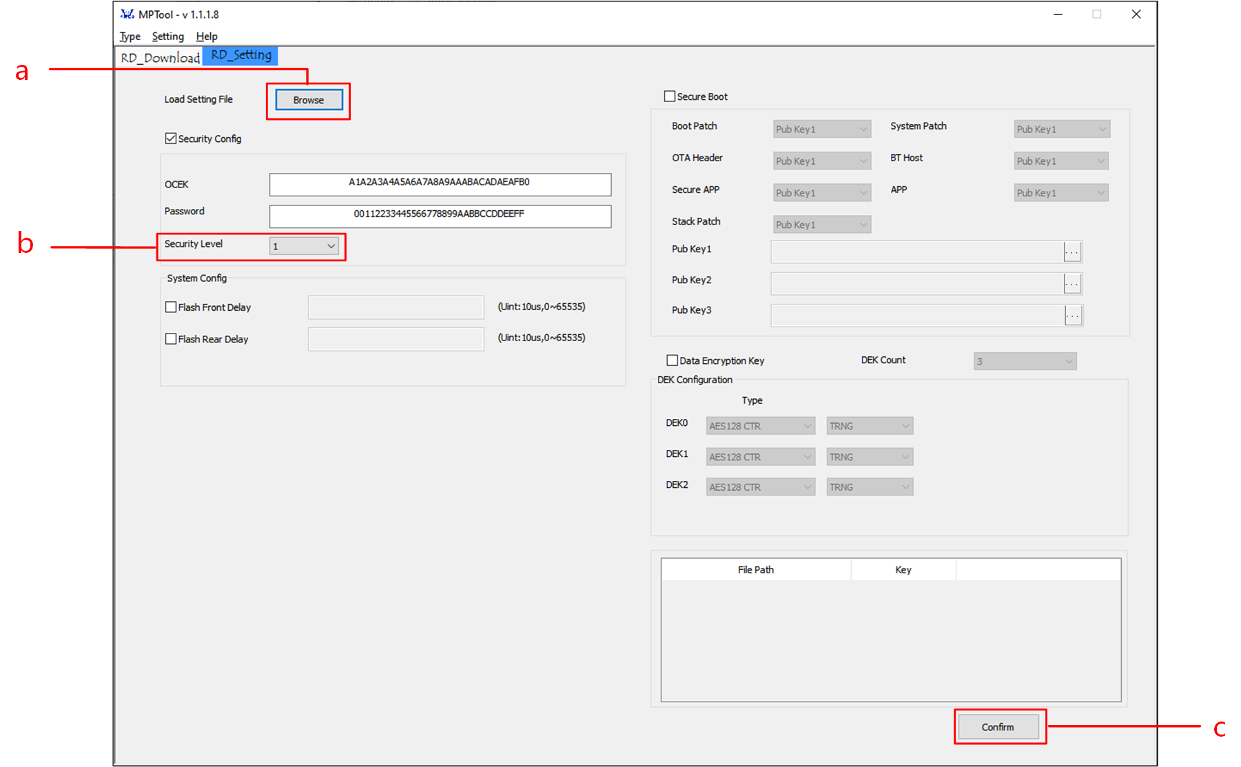
Generate the File to Program eFuse
Click Browse button to import
key.jsonfile in RD Setting UI.Select the appropriate Security Level for the project.
Click Confirm button to generate
EfuseWrite.jsonfile, which can be released to factory for programming eFuse.
-
Program eFuse in factory.
Above all, confirm that MP Tool is in mass production mode: Click item on the toolbar.
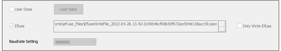
Select the File to be Programmed in eFuse
Tick Efuse in MP Setting UI and Select the File to be Programmed in eFuse.
Click to program eFuse.
Password Debug
When the security level is set to 1 or 2, the SWD interface is disabled as a security measure. However, developers can reactivate the SWD interface using the Password debug feature. This allows authorized developers to regain access to the SWD interface for debugging purposes while maintaining the overall security of the system.

Use PASSWORD to Unlock SWD
The steps are as follows:S
Open serial port in RD Download interface.
Tick Password.
Type in the plaintext of the password defined in the
key.jsonfile.Click the Unlock button.
The IC will reboot.
The SWD interface will be reactivated after the reboot process.