LCDC
The document primarily introduces an overview of the LCDC demo application, covering its requirements, environment setup, configuration, compilation and download procedures, experimental verification, code overview, and project structure. The LCDC demo application provides a simple example of how to use QSPI interface, I8080 interface, or SPI interface to communicate with a liquid crystal display controller. The document offers a detailed and comprehensive guide, covering every aspect from environment setup to code implementation, to help developers quickly get started with and test the LCDC demo application.
Requirements
The sample supports the following development kits:
Hardware Platforms |
Board Name |
Build Target |
|---|---|---|
RTL87x3E EVB |
|
|
RTL87x3D HDK |
RTL87x3D EVB |
|
RTL87x3EP HDK |
RTL87x3EP EVB |
|
Note
To purchase EVB, please visit https://www.realmcu.com/en/Home/Shop.
When built for an xxx_16M_xxx build target, the sample is configured to build and run with a 16M flash map.
To quickly set up the development environment, please refer to the detailed instructions provided in Quick Start.
LCD
The default supported LCD models in the application are listed in the following table:
Board Name |
LCD |
|---|---|
RTL87x3E EVB |
SH8601Z |
RTL87x3D EVB |
SH8601Z |
RTL87x3EP EVB |
SH8601Z |
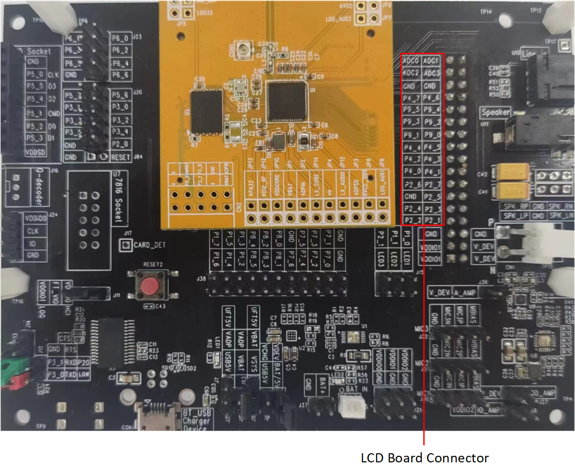
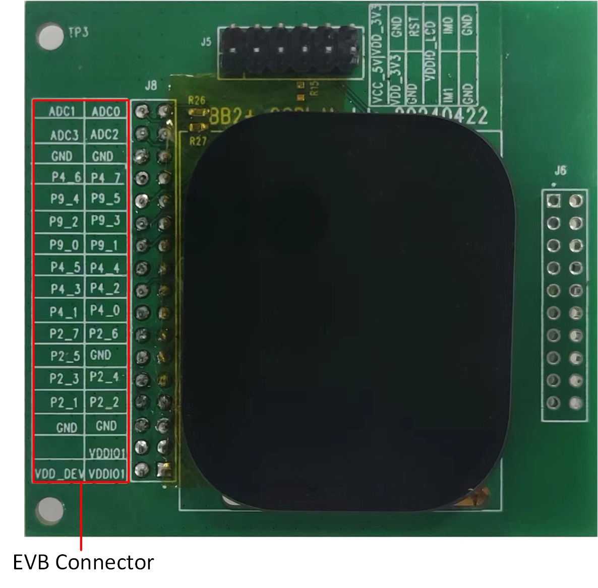
For convenience in testing the LCD, we have developed an adapter board. Simply plug the adapter board into the card slot of the EVB, and it is possible to test and use the LCD.
RTL87x3E and RTL87x3EP EVB
The LCD model is connected to the EVB via an adapter board. Simply plug the adapter board into 'J35' of the EVB.
RTL87x3EP EVB
LCD Model for RTL87x3E or RTL87x3EP
The mapping relationship between the LCD and EVB pins is shown in the following table:
LCD |
EVB |
|---|---|
SPI_CLK |
P9_4 |
SPI_SIO3 |
P9_5 |
SPI_CSN |
P9_2 |
SPI_SIO0 |
P9_3 |
SPI_SIO2 |
P9_0 |
SPI_SIO1 |
P9_1 |
LCD_RST |
P4_4 |
TE |
P2_2 |
LCD_AVDD_EN |
P2_3 |
RTL87x3D EVB
The LCD model is connected to the EVB via an adapter board. Simply plug the adapter board into 'CON4' of the EVB.
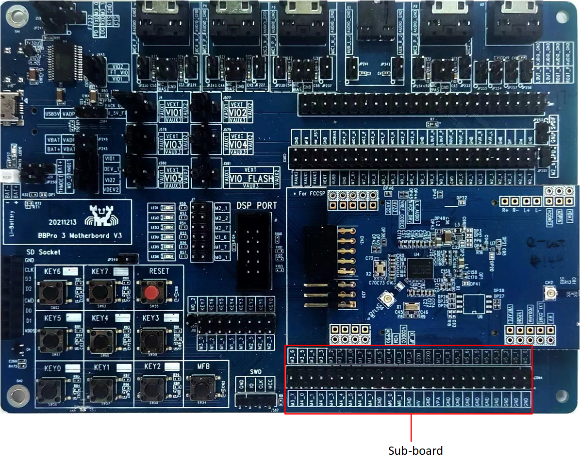
RTL87x3D EVB
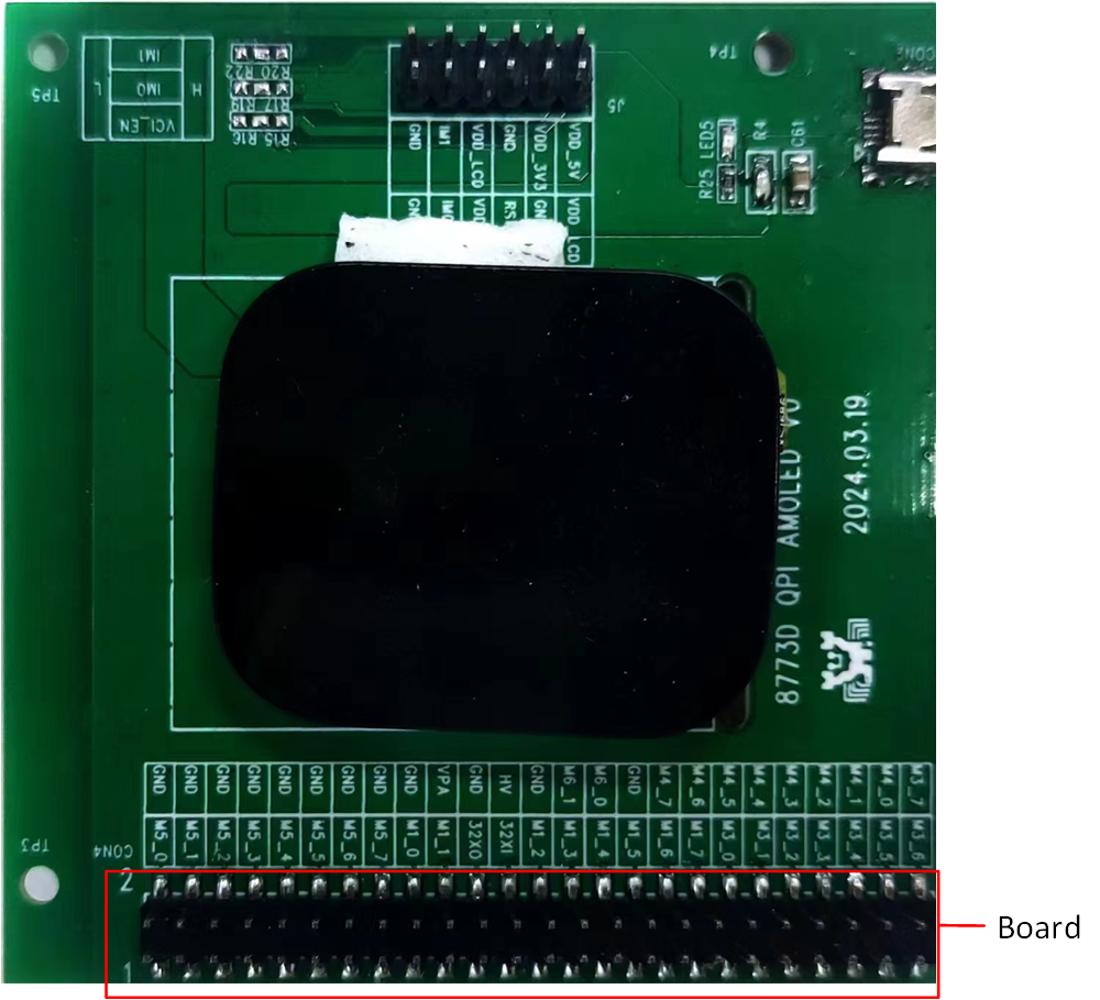
LCD Model for RTL87x3D
The mapping relationship between the LCD and EVB pins is shown in the following table:
LCD |
EVB |
|---|---|
SPI_CLK |
P3_2 |
SPI_SIO3 |
P3_7 |
SPI_CSN |
P3_3 |
SPI_SIO0 |
P3_4 |
SPI_SIO2 |
P3_6 |
SPI_SIO1 |
P3_5 |
LCD_RST |
P5_2 |
TE |
P5_4 |
LCD_AVDD_EN |
P5_5 |
Configurations
To select a specific LCD device, users can modify the macro TARGET_LCD_DEVICE in src\sample\lcdc_demo\app_gui.h.
#define TARGET_LCD_DEVICE LCD_DEVICE_SH8601Z
The following table lists the LCD devices supported by different ICs:
IC Type |
Supported LCD Devices |
|---|---|
RTL87x3D |
|
|
|
|
|
RTL87x3E |
|
|
|
|
|
|
|
|
|
|
|
RTL87x3EP |
|
|
If the device is not supported, add it to the module files:
src\mcu\module\lcd_module\module_lcd_qspi.csrc\mcu\module\lcd_module\module_lcd_8080.csrc\mcu\module\lcd_module\module_lcd_qspi_1b.csrc\mcu\module\lcd_module\module_lcd_spi.csrc\mcu\module\lcd_module\module_lcd_lcdc_qspi.c
Note
RTL87x3D doesn't support I8080 interface.
Building and Downloading
Detailed information about building and downloading can be found in Building and Downloading.
This sample can be found under board\evb\lcdc_demo in the SDK folder structure. Take the project rtl87x3e_lcdc_demo.uvprojx and target lcdc_demo_16M_bank0 as an example. To build and run the sample with the Keil development environment, follow the steps listed below:
Open
rtl87x3e_lcdc_demo.uvprojx.-
Choose the build target
lcdc_demo_16M_bank0.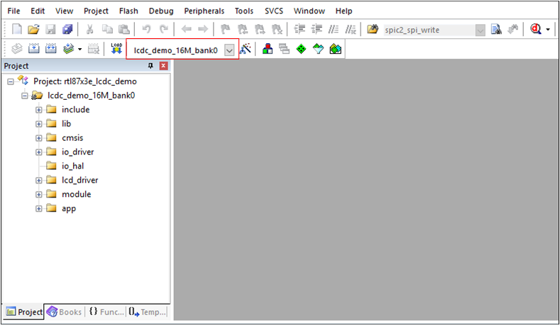
Choose Build Target
-
Build the target.
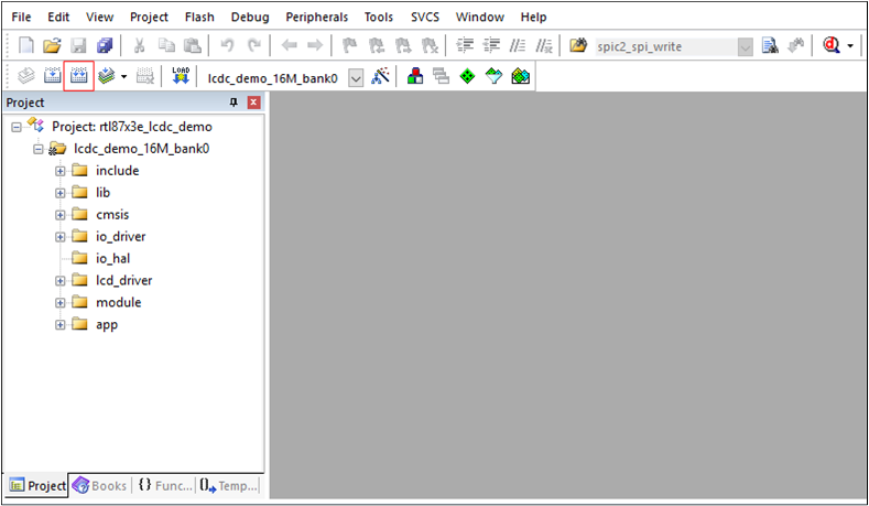
Building
After a successful compilation, the APP bin file
lcdc_demo_bank0_MP-v0.0.0.0-xxx.binwill be generated in the directorybin\rtl87x3e\flash_16M\bank0. Download the generated APP bin
lcdc_demo_bank0_MP-v0.0.0.0-xxx.bininto the EVB board.Press the Reset button on the EVB board.
Experimental Verification
Press the Reset button on the EVB board, and if the boot is successful, the LCD will be filled with blue color.
Code Overview
The LCDC demo application overview will be introduced according to the following parts:
The LCDC demo project overview will be introduced in the chapter Source Code Directory.
The LCDC demo project source code overview will be introduced in the chapter Source Code Overview.
Source Code Directory
This section describes the project directory and project structure. The reference files directory is as follows:
Project directory:
board\evb\lcdc_demo.Project source code directory:
src\sample\lcdc_demo.
Source files in the sample project are currently categorized into several groups as below:
└── Project: lcdc_demo_16M_bank0
    ├── include                          ROM UUID header files. Users do not need to modify it.
    ├── lib                              Includes all binary symbol files that the user application is built on.
    ├── cmsis                            The cmsis source code. Users do not need to modify it.
    ├── io_driver                        The IO driver code. Users do not need to modify it.
    ├── io_hal                           The IO HAL layer code. Users do not need to modify it.
    ├── lcd_driver                       The driver of the LCD device. Users could add the vendor's LCD driver according to the hardware setup.
    ├── module                           The wrapper layers of the LCD, touchpad, psram driver. Users could alter this according to the specific driver.
    └── app                              The application source code.
Source Code Overview
This section describes some parts of the source codes used in the application of this project.
Initialization
The main function is invoked when the application is powered on or the chip is reset, and it performs the following initialization functions:
int main(void)
{
   DBG_DIRECT("APP MAIN, Demo for LCD");

   app_io_resource_request_init();
   display_clock_config();
#if (LCD_INTERFACE == LCD_INTERFACE_QSPI)
   lcd_pin_config(LCD_RST);
#if (TARGET_LCD_DEVICE == LCD_DEVICE_ST77916)
   lcd_bl_pin_config(LCD_BL);
#endif
#elif (LCD_INTERFACE == LCD_INTERFACE_QSPI_1_BIT)
   lcd_pin_config(LCD_RST, LCD_DCX);
#elif (LCD_INTERFACE == LCD_INTERFACE_8080)
   lcd_pin_config(LCD_RST, LCD_POWER_EN, LCD_8080_BL);
#elif (LCD_INTERFACE == LCD_INTERFACE_SPI)
   lcd_pin_config(LCD_RST, LCD_DCX, LCD_SPI_CS, LCD_SPI_CLK, LCD_SPI_MOSI);
#elif (LCD_INTERFACE == LCD_INTERFACE_LCDC_QSPI)
   lcd_pin_config(LCD_RST);
#endif
#if (TARGET_LCD_DEVICE == LCD_DEVICE_ST7801)
   lcd_vci_en_pin_config(VCI_EN);
#elif (TARGET_LCD_DEVICE == LCD_DEVICE_SH8601Z)
   lcd_avdd_en_pin_config(LCD_AVDD_EN);
#endif
#if (ENABLE_TE_FOR_LCD == 1)
   lcd_te_pin_config(LCD_TE);
#endif
   rtk_lcd_hal_init();
   rtk_lcd_hal_rect_fill(0, 0, rtk_gui_config.lcd_width, rtk_gui_config.lcd_hight, BLUE);
   task_init();
   os_sched_start();

   return 0;
}
See Also
Please refer to the relevant API Reference: