GUI
The document primarily introduces an overview of the GUI demo application, covering its requirements, environment setup, tools, configuration, compilation and download procedures, experimental verification, code overview, and project structure. GUI demo is a simple example that demonstrates how to use a GUI, implementing a basic UI design with a touchpad as the input device. The document offers a detailed and comprehensive guide, covering every aspect from environment setup to code implementation, to help developers quickly get started with and test the GUI demo application.
Requirements
The sample supports the following development kits:
Hardware Platforms |
Board Name |
Build Target |
|---|---|---|
RTL87x3E EVB |
|
|
RTL87x3D HDK |
RTL87x3D EVB |
|
RTL87x3EP HDK |
RTL87x3EP EVB |
|
Note
To purchase EVB, please visit https://www.realmcu.com/en/Home/Shop.
When built for an xxx_16M_xxx build target, the sample is configured to build and run with a 16M flash map.
To quickly set up the development environment, please refer to the detailed instructions provided in Quick Start.
Touchpad and LCD
The default supported touch screen and LCD models in the application are listed in the following table:
Board Name |
Touchpad |
LCD |
|---|---|---|
RTL87x3E EVB |
CHSC5816 |
SH8601Z |
RTL87x3D EVB |
CHSC5816 |
SH8601Z |
RTL87x3EP EVB |
CHSC5816 |
SH8601Z |
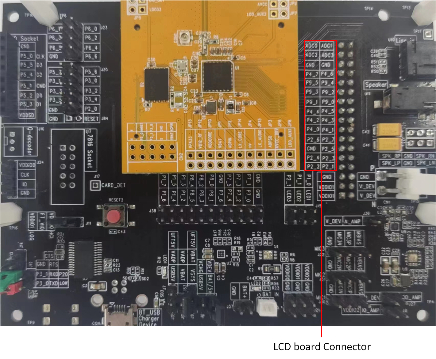
For convenience in testing the touchpad and LCD, we have developed an adapter board. Simply plug the adapter board into the card slot of the EVB, and it is possible to test and use the touchpad and LCD.
RTL87x3E and RTL87x3EP EVB
The touch screen and LCD model are connected to the EVB via an adapter board. Simply plug the adapter board into 'J35' of the EVB.
RTL87x3EP EVB
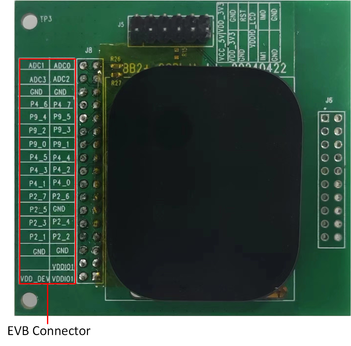
Touch Screen and LCD Model for RTL87x3E or RTL87x3EP
The mapping relationship between the touchpad or LCD and EVB pins is shown in the following table:
Touchpad and LCD |
EVB |
|---|---|
TP_SCL |
ADC_0 |
TP_SDA |
ADC_1 |
TP_INT |
ADC_2 |
TP_RST |
ADC_3 |
SPI_CLK |
P9_4 |
SPI_SIO3 |
P9_5 |
SPI_CSN |
P9_2 |
SPI_SIO0 |
P9_3 |
SPI_SIO2 |
P9_0 |
SPI_SIO1 |
P9_1 |
LCD_RST |
P4_4 |
TE |
P2_2 |
LCD_AVDD_EN |
P2_3 |
RTL87x3D EVB
The touch screen and LCD model are connected to the EVB via an adapter board. Simply plug the adapter board into 'CON4' of the EVB.
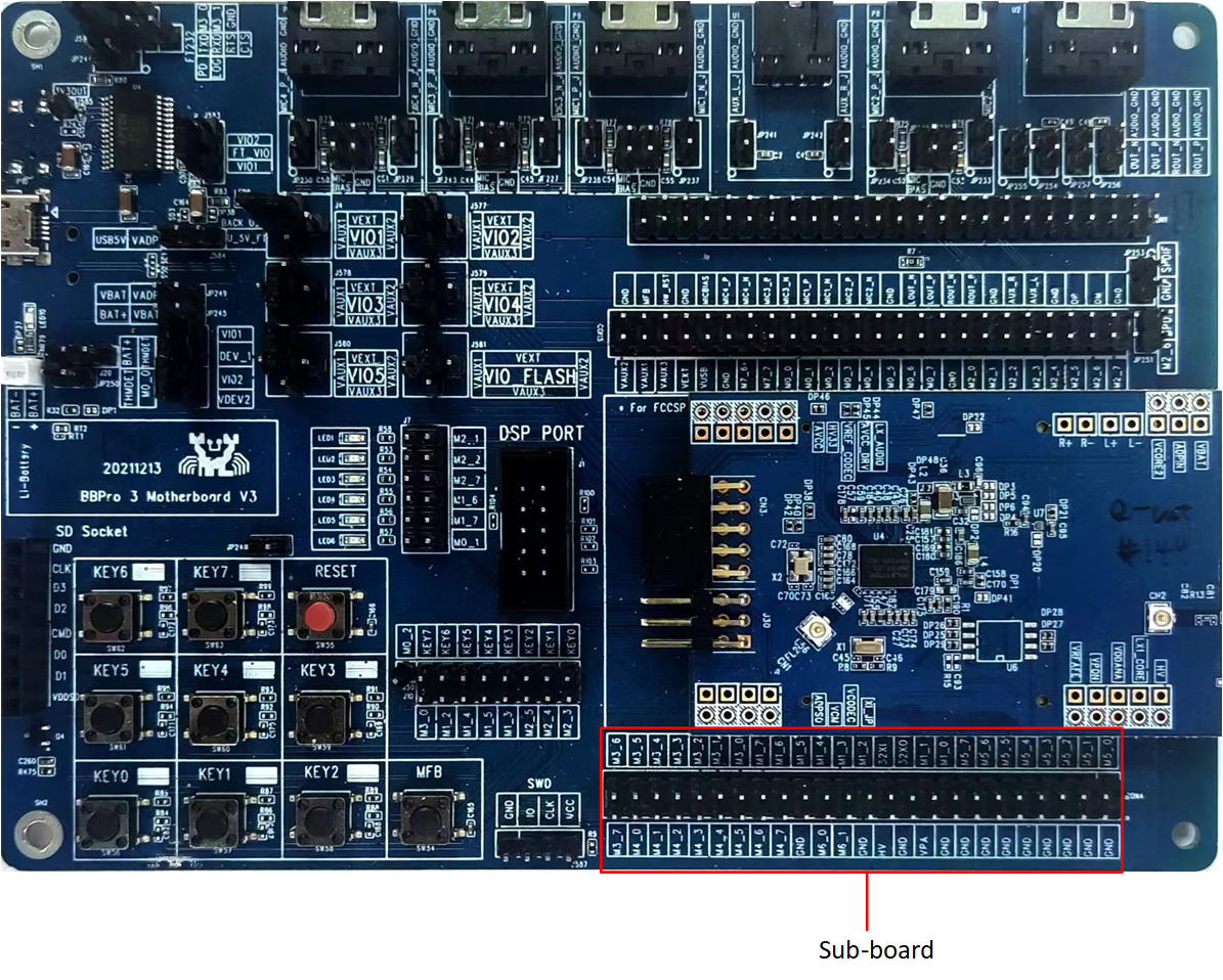
RTL87x3D EVB
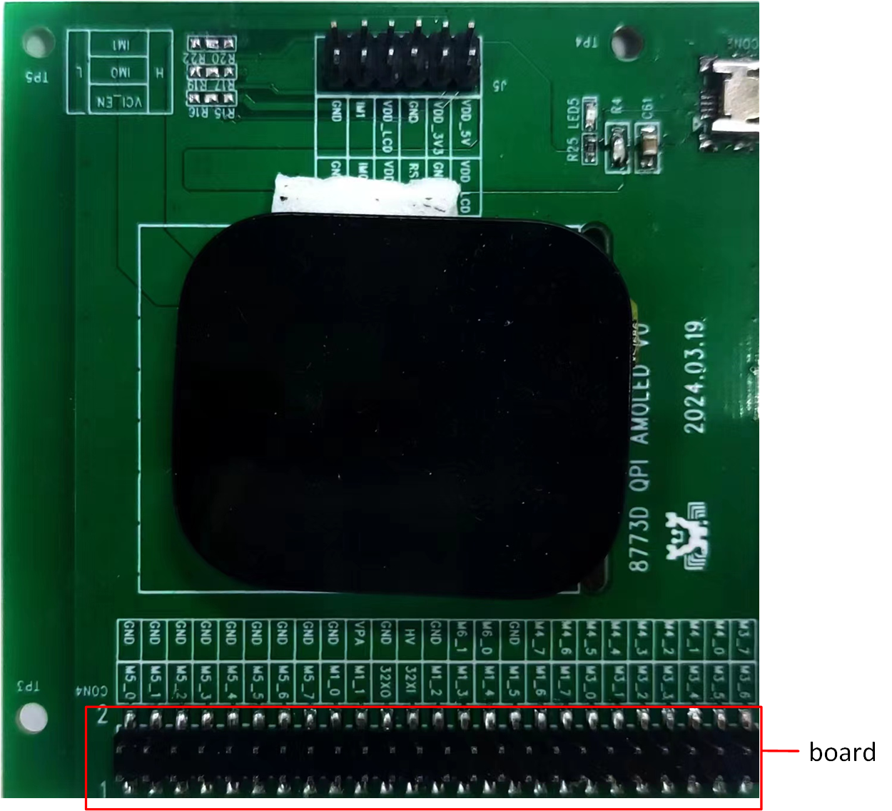
Touch Screen and LCD Model for RTL87x3D
The mapping relationship between the touchpad or LCD and EVB pins is shown in the following table:
Touchpad and LCD |
EVB |
|---|---|
TP_SCL |
P6_0 |
TP_SDA |
P5_7 |
TP_INT |
P5_6 |
TP_RST |
P5_3 |
SPI_CLK |
P3_2 |
SPI_SIO3 |
P3_7 |
SPI_CSN |
P3_3 |
SPI_SIO0 |
P3_4 |
SPI_SIO2 |
P3_6 |
SPI_SIO1 |
P3_5 |
LCD_RST |
P5_2 |
TE |
P5_4 |
LCD_AVDD_EN |
P5_5 |
Tools
SDK provides image conversion tools that facilitate the conversion of images, such as JPG, PNG, BMP, into burnable BIN files. The image conversion tool provided by the SDK is located in the sdk\tool path. The interface of the image conversion tool is as follows:
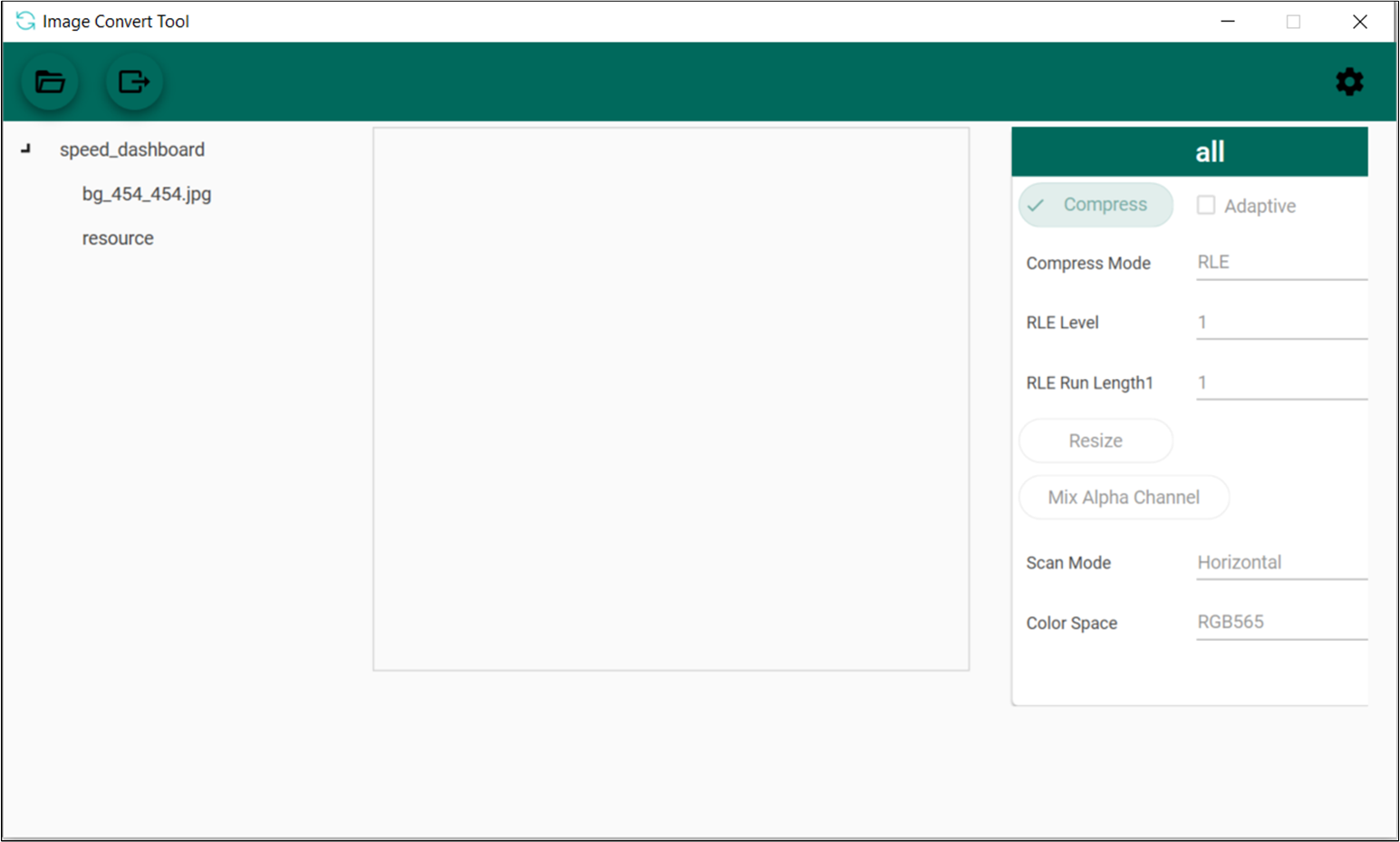
Image Convert Tool
To learn more about the tool's usage guidelines, please refer to Image Convert Tool.
Files
The previous chapter introduces the steps for converting image resources. For font resource conversion, consult with FAE to address the requirements. Once both the image and font resources have been generated as binary files, the packaging tool can be used to convert them into the final user data binary file.
The GUI package tool provided by the SDK is located in the src\app\panel\application\root_image path.
Place the bin files of the images into the
src\app\panel\application\root_image\root\paneldirectory.Place the bin files of the fonts into
src\app\panel\application\root_image\root\fontdirectory.Execute the
gen_root_image.bat.A user data bin file will be generated in the current path. Please select the file with the suffix and random number.
Note
While packing the userdata file, a resource.h file will also be generated. This file is used to generate the APP bin file, and the APP code can use the addresses of the images or fonts in this file to index the related resources.
Configurations
To select a specific LCD device and touchpad device, modify the macros TARGET_LCD_DEVICE and TARGET_TOUCH_DEVICE in src\app\panel\application\app_gui.h.
#define TARGET_LCD_DEVICE                    LCD_DEVICE_SH8601Z
#define TARGET_TOUCH_DEVICE                  TOUCH_DEVICE_CHSC5816
The following table lists the LCD devices supported by different ICs:
IC Type |
Supported LCD Devices |
|---|---|
RTL87x3D |
|
|
|
|
|
RTL87x3E |
|
|
|
|
|
|
|
|
|
|
|
RTL87x3EP |
|
|
If the LCD device is not supported, add it to the module files.
src\mcu\module\lcd_module\module_lcd_qspi.csrc\mcu\module\lcd_module\module_lcd_8080.csrc\mcu\module\lcd_module\module_lcd_qspi_1b.csrc\mcu\module\lcd_module\module_lcd_spi.csrc\mcu\module\lcd_module\module_lcd_lcdc_qspi.c
The following table lists the touchpad devices supported by different ICs:
IC Type |
Supported Touchpad Devices |
|---|---|
RTL87x3D |
|
|
|
|
|
|
|
RTL87x3E |
|
|
|
|
|
|
|
|
|
RTL87x3EP |
|
|
|
|
Enable or disable PSRAM by modifying the macro
ENABLE_PSRAM_FOR_LCDinsrc\app\panel\application\app_gui.h.Enable or disable the TE function by modifying the macro
ENABLE_TE_FOR_LCDinsrc\app\panel\application\app_gui.h.Enable or disable the frame buffer direction rotation function by modifying the macro
FB_DIRECTION_ROTATEinsrc\app\panel\application\app_gui.h.
Building and Downloading
Detailed information about building and downloading can be found in Building and Downloading.
This sample can be found under board\evb\gui_demo in the SDK folder structure.
Take the project rtl87x3e_gui_demo.uvprojx and target gui_demo_16M_bank0 as an example. To build and run the sample with the Keil development environment, follow the steps listed below:
Open
rtl87x3e_gui_demo.uvprojx.-
Choose the build target
gui_demo_16M_bank0.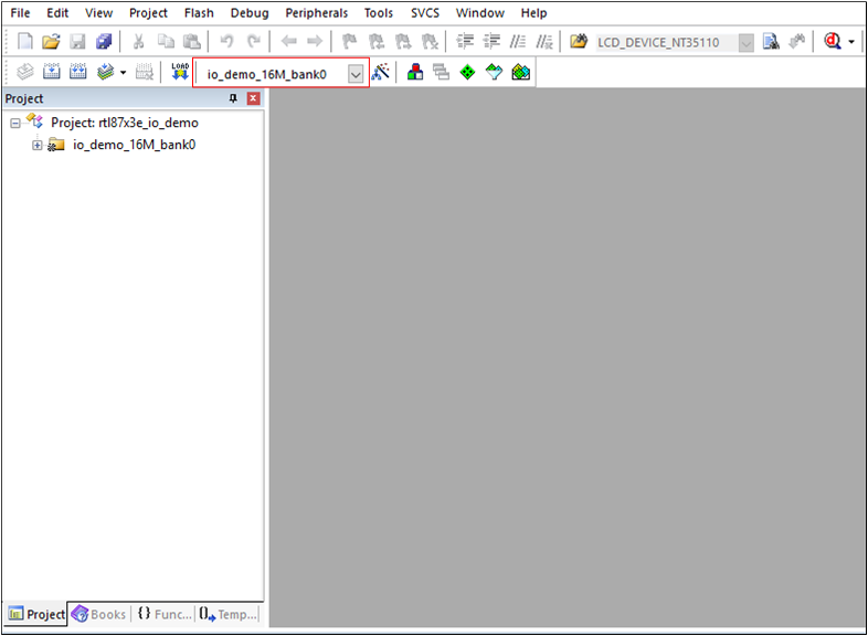
Choose Build Target
-
Build the target.

Building
After a successful compilation, the APP bin file
gui_demo_bank0_MP-v0.0.0.0-xxx.binwill be generated in the directorybin\rtl87x3e\flash_16M\bank0. Download the generated APP bin
gui_demo_bank0_MP-v0.0.0.0-xxx.bininto the EVB board. Download a resource bin namedroot_MP-xxx.bininto the EVB board, which includes font and image resources. The resource bin prefixed withrootis in the directorysrc\app\panel\application\root_image.Press the Reset button on the EVB board.
Experimental Verification
Press the Reset button on the EVB board, and if the boot succeeds, the LCD will show the demo images.
Swipe left or right on the LCD to switch the demo images.
Code Overview
The GUI demo application overview will be introduced according to the following parts:
The GUI demo project overview will be introduced in the chapter Source Code Directory.
The GUI demo project source code overview will be introduced in the chapter Source Code Overview.
Source Code Directory
This section describes the directory and structure of the project. The project directory is as follows:
Project directory:
board\evb\gui_demo.Project source code directory:
src\app\panel.GUI source code directory:
src\sample\gui.
Source files in the sample project are currently categorized into several groups as below:
└── Project: gui_demo_16M_bank0
    ├── include                          ROM UUID header files. Users do not need to modify it.
    ├── lib                              Includes all binary symbol files that user application is built on.
    ├── cmsis                            The cmsis source code. Users do not need to modify it.
    ├── io_driver                        The IO driver code. Users do not need to modify it.
    ├── io_hal                           The IO HAL layer code. Users do not need to modify it.
    ├── lcd_driver                       The driver of the LCD device. Users could add the vendor LCD driver according to the hardware setup.
    ├── module                           The wrapper layers of LCD, touchpad, PSRAM driver. Users could alter this according to the specific driver.
    ├── rtk_hal                          The HAL layer of the vendor LCD and touchpad device.
    ├── app                              The application source code.
    ├── realgui/port                     The source code of the RTK GUI framework. Users can modify the gui_port_xxx.c code to change the behavior and parameters of the vendor device.
    ├── realgui/3rd                      The source code of the RTK GUI framework. Users do not need to modify it.
    ├── realgui/app                      The source code of the RTK GUI framework. Users do not need to modify it.
    ├── realgui/dc                       The source code of the RTK GUI framework. Users do not need to modify it.
    ├── realgui/engine                   The source code of the RTK GUI framework. Users do not need to modify it.
    ├── realgui/input                    The source code of the RTK GUI framework. Users do not need to modify it.
    ├── realgui/misc                     The source code of the RTK GUI framework. Users do not need to modify it.
    ├── realgui/server                   The source code of the RTK GUI framework. Users do not need to modify it.
    ├── realgui/widget                   The source code of the RTK GUI framework. Users do not need to modify it.
    ├── realgui/ppe                      The source code of the RTK GUI framework. Only RTL87x3EP supports it.
    └── realgui/benchmark                The source code of the RTK GUI benchmark.
Source Code Overview
This section provides a description of certain portions of the source code used in the application for this project.
Initialization
The main function is invoked upon application power-on or chip reset, performing the following initialization functions:
int main(void)
{
   DBG_DIRECT("Dashboard demo");
   DBG_DIRECT("APP COMPILE TIME: [%s - %s]", __DATE__, __TIME__);
#if (ENABLE_PPE_FUNCTION == 1)
   ram_config();
#endif

   app_io_resource_request_init();

   app_system_clock_init();
   app_components_init();
   app_task_init();

   /* Start scheduler. */
   os_sched_start();
}
Please refer to the GUI demo source code for the initialization function declaration.
System Clock Initialize
To run the GUI on SoC, it is necessary to increase the CPU frequency to at least 100MHz, and the SPIC must be set to 4-bit mode with a 160MHz clock source. If enabling the PSRAM, the clock of SPIC needs to be switched to at least 80MHz.
/* Set the CPU frequency */
#if (TARGET_RTL8773DO == 1)
#define DASHBOARD_CPU_FREQ_MHZ             (160)
#else
#define DASHBOARD_CPU_FREQ_MHZ             (100)
#endif
static uint8_t dashboard_cpu_handle = 0;
uint32_t cpu_freq = 0;
pm_cpu_freq_req(&dashboard_cpu_handle, DASHBOARD_CPU_FREQ_MHZ, &cpu_freq);

/* Set the SPIC to 4-bit mode */
#if (CONFIG_SOC_SERIES_RTL8773E == 1)
bool ret = fmc_flash_try_high_speed_mode(FMC_SPIC_ID_0, FMC_FLASH_NOR_4_BIT_DTR_MODE);
#else
bool ret = fmc_flash_try_high_speed_mode(FMC_SPIC_ID_0, FMC_FLASH_NOR_4_BIT_MODE);
#endif

/* Set the SPIC clock to 160MHz */
#define DASHBOARD_SPIC0_FREQ_MHZ           (160)
uint32_t spic0_freq = 0;
ret = fmc_flash_nor_clock_switch(FMC_SPIC_ID_0, DASHBOARD_SPIC0_FREQ_MHZ, &spic0_freq);

/* Set the SPIC clock of PSRAM */
#if (CONFIG_SOC_SERIES_RTL8773E == 1)
#define LCD_PSRAM_FREQ_MHZ   160
#else
#define LCD_PSRAM_FREQ_MHZ   80
#endif
#if ((TARGET_RTL87X3E == 1) || (CONFIG_SOC_SERIES_RTL8773E == 1))
   uint32_t psram_freq = 0;
   bool fmc_psram_winbond_opi_init_ret = fmc_psram_winbond_opi_init();

   bool fmc_psram_clock_switch_ret = fmc_psram_clock_switch(LCD_PSRAM_FREQ_MHZ, &psram_freq);
#elif (TARGET_RTL8773DO == 1)
   uint32_t actual_clock = 0;

   bool fmc_psram_winbond_opi_init_ret = fmc_psram_spi_winbond_opi_init();

   bool fmc_psram_clock_switch_ret = fmc_psram_spi_clock_switch(LCD_PSRAM_INDEX, 80, &actual_clock);
#endif
GUI Server Initialize
First, initialize the LCD and the touch device in this function.
void app_components_init(void)
{
#if (LCD_INTERFACE == LCD_INTERFACE_QSPI)
   lcd_pin_config(LCD_RST);
#if (TARGET_LCD_DEVICE == LCD_DEVICE_ST77916)
   lcd_bl_pin_config(LCD_BL);
#endif
#elif (LCD_INTERFACE == LCD_INTERFACE_QSPI_1_BIT)
   lcd_pin_config(LCD_RST, LCD_DCX);
#elif (LCD_INTERFACE == LCD_INTERFACE_8080)
   lcd_pin_config(LCD_RST, LCD_POWER_EN, LCD_8080_BL);
#elif (LCD_INTERFACE == LCD_INTERFACE_SPI)
   lcd_pin_config(LCD_RST, LCD_DCX, LCD_SPI_CS, LCD_SPI_CLK, LCD_SPI_MOSI);
#elif (LCD_INTERFACE == LCD_INTERFACE_LCDC_QSPI)
   lcd_pin_config(LCD_RST);
#endif
#if (TARGET_LCD_DEVICE == LCD_DEVICE_ST7801)
   lcd_vci_en_pin_config(VCI_EN);
#elif (TARGET_LCD_DEVICE == LCD_DEVICE_SH8601Z)
   lcd_avdd_en_pin_config(LCD_AVDD_EN);
#endif
#if (ENABLE_TE_FOR_LCD == 1)
   lcd_te_pin_config(LCD_TE);
#endif
   drv_lcd_init();

   touch_pin_config(TOUCH_I2C_SCL, TOUCH_I2C_SDA, TOUCH_INT, TOUCH_RST);
   drv_touch_init();
}
The GUI server and the UI design are initialized in the gui_main function at the entry of the APP task.
void gui_main(void)
{
   gui_server_init();
   extern gui_app_t *get_app_panel(void);
   gui_app_install(get_app_panel(), get_app_panel()->ui_design, NULL);
   gui_app_startup(get_app_panel());
}
See Also
Please refer to the relevant API Reference: