SPI3W
Sample List
This chapter introduces the details of the SPI3W sample. The RTL87x2G provides the following samples for the SPI3W peripheral.
Functional Overview
The 3-wire serial peripheral interface (SPI3W) supports single write and single/burst read. The host controller can use the SPI3W to write and read registers in the sensor, and to read out the motion information. The host controller always initiates communication; the sensor never initiates data transfers. SPI3W_CS, SPI3W_CLK and SPI3W_DATA may be driven directly by the host controller. SPI3W_DATA may also be driven by the sensor when data is read out from sensor registers.
Feature List
Support 2-wire and 3-wire communication.
Support single write.
Support single/burst read.
Programmable delay between write and read.
Max SPI3W Clock 2MHz.
Half duplex.
Master only.
Block Diagram
Here is the block diagram of SPI3W. By invoking the MCU Firmware, functions such as SPI3W Write/Read are implemented. The hardware interacts with external devices through the DATA line for data exchange.
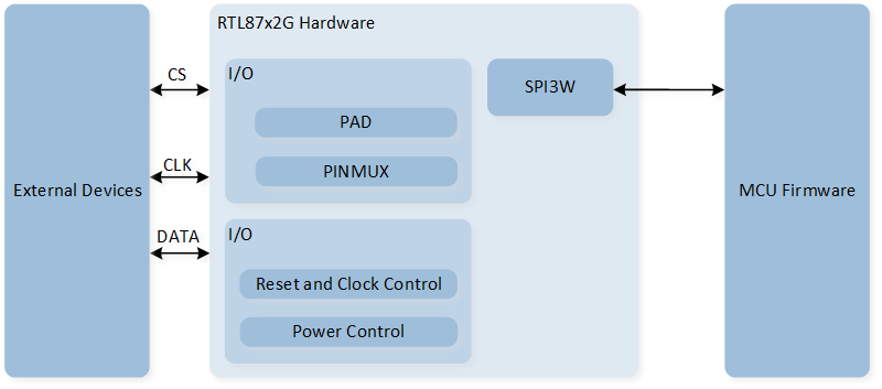
System Block Diagram of SPI3W
Data Format
The data contains two bytes, the first byte is the address bit, the highest bit is the read/write control bit, and the second byte is the data byte. As shown below:

3-Wire SPI Data Format
Write Operation
Write data from the controller to the sensor, only supports single write mode, as shown in the figure below. No delay needs to be added between the address byte and the data byte.
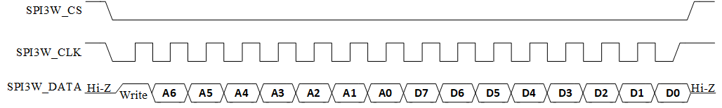
SPI3W write mode format
Read Operation
Single Read Mode
In single read mode, SPI3W will first send an address byte, after which the SPI3W_DATA line switches to receive mode to receive a data byte sent back by the counterpart sensor.
Between the first byte (address byte) and the second byte (data byte), a delay of T-Hold needs to be added.
This delay is configured by SPI3W_InitTypeDef::SPI3W_ReadDelay.
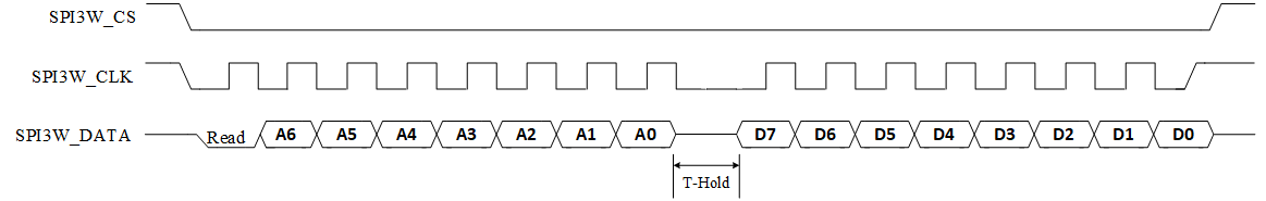
SPI3W single read format
Burst Read Mode
In burst read mode, SPI can continuously read multiple bytes of data. SPI3W will first send an address byte, after which the SPI3W_DATA line switches to receive mode to receive multiple data bytes from the responding sensor.
Between the first byte (address byte) and the second byte (data byte 0), a delay of T-Hold needs to be added.
This delay is configured by SPI3W_InitTypeDef::SPI3W_ReadDelay.
There is no delay between the third byte (data byte 1) and the second byte (data byte 0) until the end of a burst read.
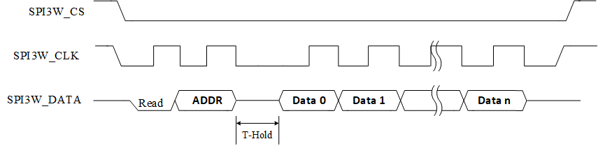
SPI3W burst read format
Polling Mode Flow
Polling Write Flow
The flow for writing data in SPI3W polling mode is as shown in the diagram:

SPI3W polling write flow
bool spi3wire_writebyte(uint8_t address, uint8_t data)
{
   uint32_t timeout = 0;

   /* Check 3wire spi busy or not */
   while (SPI3W_GetFlagStatus(SPI3W_FLAG_BUSY) == SET)
   {
      timeout++;
      if (timeout > 0x1ffff)
      {
            return false;
      }
   }
   /* Write data */
   SPI3W_StartWrite(address, data);

   timeout = 0;
   while (SPI3W_GetFlagStatus(SPI3W_FLAG_BUSY) == SET)
   {
      timeout++;
      if (timeout > 0x1ffff)
      {
            return false;
      }
   }
   return true;
}
Polling Read Flow
The flow for reading data in SPI3W polling mode is as shown in the diagram:

SPI3W polling read flow
uint8_t spi3wire_readbyte(uint8_t address)
{
uint8_t reg_value = 0;
uint32_t timeout = 0;
/* Check spi busy or not */
while (SPI3W_GetFlagStatus(SPI3W_FLAG_BUSY) == SET)
{
timeout++;
if (timeout > 0x1ffff)
{
break;
}
}
/* Clear Receive data length */
SPI3W_ClearRxDataLen();
SPI3W_StartRead(address, 1);
timeout = 0;
while (SPI3W_GetFlagStatus(SPI3W_FLAG_BUSY) == SET)
{
timeout++;
if (timeout > 0x1ffff)
{
break;
}
}
/* Get the length of received data */
while (SPI3W_GetRxDataLen() == 0);
/* Read data */
SPI3W_ReadBuf(®_value, 1);
return reg_value;
}