IR
Sample List
This chapter introduces the details of the IR sample. The RTL87x2G provides the following samples for the IR peripheral.
Functional Overview
The IR module provides a flexible way of transmitting and receiving IR code used in remote controls. It could send IR waveform within IR carrier and received IR waveform with IR carrier.
Feature List
-
IR Transmitter Feature:
Programmable IR carrier frequency (5kHz~2MHz).
Programmable IR carrier duty.
Programmable IR carrier cycle number.
TX FIFO Depth: 32.
GDMA Support.
-
IR Receiver Feature:
Programmable sample clock (max clock 40MHz).
Automatic/manual trigger mode.
RX FIFO Depth: 32.
GDMA Support.
Block Diagram
Here is the block diagram of IR. By invoking the MCU Firmware, functions such as IR TX/RX are implemented. IR will automatically receive/send the corresponding data through the hardware according to the Firmware settings.

System Block Diagram of IR
IR Transmit
The schematic diagram of IR Transmit is shown in the figure below.
Schematic Diagram of IR Transmit
The IR transmission function requires setting IR_InitTypeDef::IR_Mode to IR_MODE_TX.
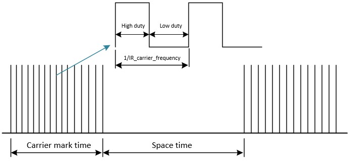
The output waveform of IR TX includes Mark waveform and Space waveform. The Mark waveform is the region with a carrier, while the Space waveform is the region without a carrier.
By default, the Mark waveform first outputs a high duty cycle, followed by a low duty cycle. The Space waveform defaults to outputting a low level.
IR TX data consists of 32 bits, and by default, the meaning of the data in the FIFO is as follows:
data[26:0]: Represents the duration of the (Mark / Space) waveform, time = (data[26:0] + 1) * carrier_cycle.
data[29:27]: Represents low-level compensation under the Space waveform, with a compensation time of data[29:27] * 1/8 carrier_cycle. It should be set to 0 under the Mark waveform.
data[30]: Set to 0 to represent a normal waveform, set to 1 to represent the end waveform of TX output.
data[31]: Set to 0 to represent the Space waveform, set to 1 to represent the Mark waveform.
IR Receive
The IR reception function requires setting IR_InitTypeDef::IR_Mode to IR_MODE_RX. In the IR reception function, the IR_InitTypeDef::IR_Freq parameter represents the sampling frequency.
IR reception mode is divided into manual mode and automatic mode.
Manual Mode: In manual mode, call
IR_Cmd(), the counter starts, and IR begins receiving data. SetIR_InitTypeDef::IR_RxStartModetoIR_RX_MANUAL_MODEto enable manual mode.Automatic Mode: In automatic mode, after calling
IR_Cmd(), when the input waveform of the IR meets the set trigger conditions, the counter starts, and IR begins receiving data. SetIR_InitTypeDef::IR_RxStartModetoIR_RX_AUTO_MODEto enable automatic mode, and setIR_InitTypeDef::IR_RxTriggerModeto change the trigger conditions for automatic IR reception.
In IR reception mode, when reception begins, a counter starts to record the duration of high and low levels. When the duration of the high/low level exceeds a certain value, i.e., when the counter's count value meets the set threshold, it triggers the counter threshold interrupt IR_INT_RX_CNT_THR. Generally, this interrupt is used to stop the IR reception function.
You can configure IR_InitTypeDef::IR_RxCntThrType to set whether the counter records high or low levels, and configure IR_InitTypeDef::IR_RxCntThr to set the counter threshold.
IR RX data consists of 32 bits, and by default, the meaning of the data in the FIFO is as follows:
data[30:0]: Represents the RX waveform duration, time = (data[30:0] + 1) / sample_clock.
data[31]: Represents the level of the RX waveform. 1 represents a high level, 0 represents a low level.
IR GDMA
IR GDMA TX
During the IR transmission, a GDMA burst transfer is triggered when the amount of data in the TX FIFO is less than or equal to the value set in the initialization IR_InitTypeDef::IR_TxWaterLevel.
A single GDMA burst will write GDMA_InitTypeDef::GDMA_DestinationMsize pieces of data into the IR TX FIFO.
When using IR GDMA TX, it is recommended to set the value of IR_InitTypeDef::IR_TxWaterLevel to IR_TX_FIFO_SIZE - MSize.
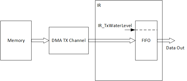
IR GDMA TX Diagram
IR GDMA RX
During the IR transmission, a GDMA burst transfer will be triggered when the amount of data in the RX FIFO is greater than or equal to the value set in the initialization IR_InitTypeDef::IR_RxWaterLevel.
A single GDMA burst will fetch GDMA_InitTypeDef::GDMA_SourceMsize pieces of data from the IR RX FIFO.
When using IR GDMA RX, it is recommended to set the value of IR_InitTypeDef::IR_RxWaterLevel to MSize.
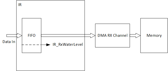
IR GDMA RX Diagram