IR Transmit
This sample demonstrates the usage of the IR transmission function.
The IR peripheral is used to transmit a large amount of data via interrupts to achieve infrared transmission functionality. A logic analyzer can be used to observe the IR transmission waveform.
Requirements
For requirements, please refer to the Requirements.
Wiring
Connect the IR TX pin P2_5 to the logic analyzer.
Configurations
-
The following macro can be configured to modify the pin definitions.
#define IR_TX_PIN P2_5 -
The following macros can be configured to modify the threshold.
#define IR_TX_FIFO_THR_LEVEL 2
Building and Downloading
For building and downloading, please refer to the Building and Downloading.
Experimental Verification
Observe the IR TX waveform within the logic analyzer.
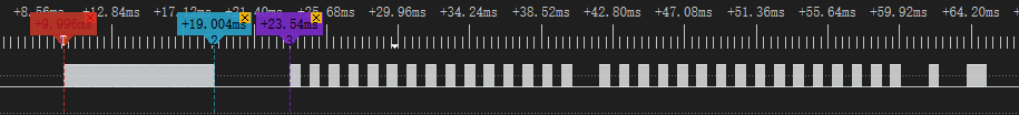
IR Transmit Waveform
Code Overview
This section introduces the code and process description for initialization and corresponding function implementation in the sample.
Source Code Directory
The directory for project file and source code are as follows:
Project directory:
sdk\samples\peripheral\ir\tx\projSource code directory:
sdk\samples\peripheral\ir\tx\src
Initialization
The initialization flow for peripherals can refer to Initialization Flow in General Introduction.
-
Call
Pad_Config()andPinmux_Config()to configure the PAD and PINMUX of the corresponding pins.void board_ir_init(void) { Pad_Config(IR_TX_PIN, PAD_PINMUX_MODE, PAD_IS_PWRON, PAD_PULL_NONE, PAD_OUT_ENABLE, PAD_OUT_LOW); Pinmux_Config(IR_TX_PIN, IRDA_TX); }
Call
RCC_PeriphClockCmd()to enable the IR clock.-
Initialize the IR peripheral:
Define the
IR_InitTypeDeftypeIR_InitStruct, and callIR_StructInit()to pre-fillIR_InitStructwith default values.Modify the
IR_InitStructparameters as needed. The IR initialization parameter configuration is shown in the table below.Call
IR_Init()to initialize the IR peripheral.
IR Hardware Parameters |
Setting in the |
IR |
|---|---|---|
Sample Clock |
38000 |
|
IR Duty Cycle |
2 |
|
IR Mode |
||
IR Tx Threshold |
|
Call
IR_INTConfig()to configure the IR transmit FIFO to reach threshold interruptIR_INT_TF_LEVEL. Configure NVIC, for details refer to Interrupt Configuration.
Functional Implementation
The flow of transmit data via IR through interrupts is shown in the figure:
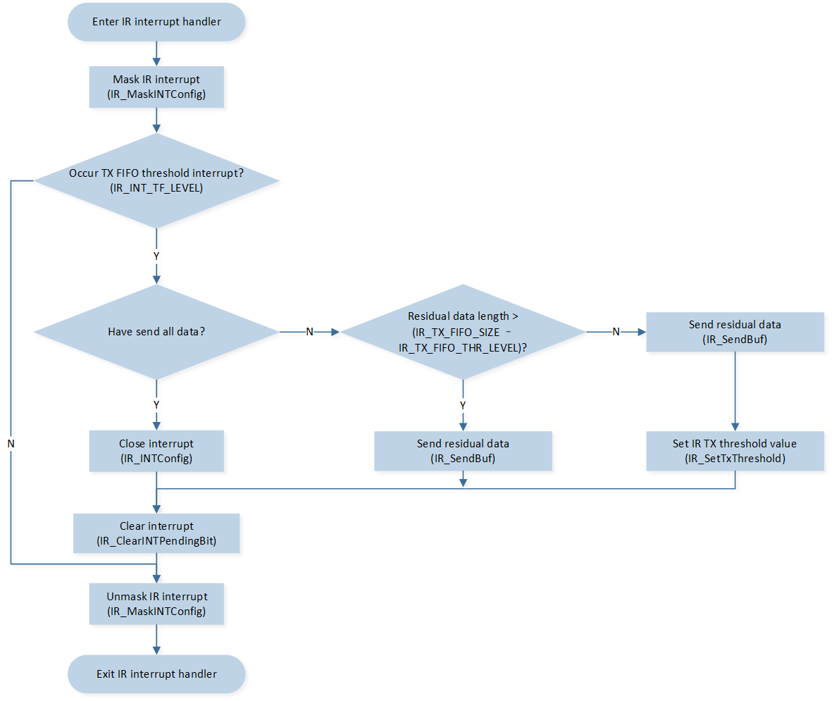
IR transmit data flow
Define IR send data array: carrier data is represented by the number of carriers or 0x80000000, no carrier data is represented by the number of carriers or 0x00000000.
Call
IR_SendBuf()function to start sending data into IR transmit FIFO.Record the number of data that have been sent
IR_TX_Count.Call
IR_Cmd()to enable IR peripheral.
IR_TxData.CarrierFreq = 38000;
IR_TxData.DataLen = 67 + 1; //2+64+1;
IR_TxData.DataBuf[0] =  0x80000000 | 0x156; //342 about 9ms
IR_TxData.DataBuf[1] =  0x00000000 | 0xAB; //171 about 4.5ms
...
IR_TxData.DataBuf[IR_TxData.DataLen - 1] =  0x80000000 | 0x15;
...
IR_SendBuf(IR_TxData.DataBuf, IR_TX_FIFO_SIZE, DISABLE);
IR_Cmd(IR_MODE_TX, ENABLE);
-
After enabling the IR peripheral, IR begins transmitting data. When the number of IR transmit FIFO data is less than the set transmission threshold (set to 2 in this example), it triggers the
IR_INT_TF_LEVELinterrupt and enters the interrupt handling function.Mask the
IR_INT_TF_LEVELinterrupt.-
Transmit IR data in batches.
If the remaining data to be transmitted is greater than the capacity of the transmit FIFO, it indicates that a large amount of data is still untransmitted. At this point, it is necessary to fill
IR_TX_FIFO_SIZE - IR_TX_FIFO_THR_LEVELdata into the IR transmit FIFO and send it.If the remaining data to be transmitted is greater than 0 but less than the capacity of the transmit FIFO, it indicates that there is not much data left, and all of it can be transmitted now. In this case, all remaining data should be filled into the IR transmit FIFO.
Otherwise, if there is no remaining data, it means all data has been transmitted, and the
IR_INT_TF_LEVELinterrupt should be disabled.
Clear the
IR_INT_TF_LEVELinterrupt pending bit and unmask theIR_INT_TF_LEVELinterrupt.
IR_MaskINTConfig(IR_INT_TF_LEVEL, ENABLE);
if ((IR_TxData.DataLen - IR_TX_Count) >= IR_TX_FIFO_SIZE)
{
    IR_SendBuf(IR_TxData.DataBuf + IR_TX_Count, (IR_TX_FIFO_SIZE - IR_TX_FIFO_THR_LEVEL), DISABLE);
    IR_TX_Count += (IR_TX_FIFO_SIZE - IR_TX_FIFO_THR_LEVEL);

    /* Clear threshold interrupt */
    IR_ClearINTPendingBit(IR_INT_TF_LEVEL_CLR);
}
else if ((IR_TxData.DataLen - IR_TX_Count) > 0)
{
    /* The remaining data is less than the TX FIFO length */

    /*  Configure TX threshold level to zero and trigger interrupt when TX FIFO is empty */
    IR_SetTxThreshold(0);
    IR_SendBuf(IR_TxData.DataBuf + IR_TX_Count, IR_TxData.DataLen - IR_TX_Count, DISABLE);
    IR_TX_Count += (IR_TxData.DataLen - IR_TX_Count);

    /* Clear threshold interrupt */
    IR_ClearINTPendingBit(IR_INT_TF_LEVEL_CLR);
}
else
{
    /* Tx completed */
    /* Disable IR tx empty interrupt */
    IR_INTConfig(IR_INT_TF_LEVEL, DISABLE);
    IR_TX_Count = 0;

    /* Clear threshold interrupt */
    IR_ClearINTPendingBit(IR_INT_TF_LEVEL_CLR);
}
See Also
Please refer to the relevant API Reference: