GPIO
Sample List
This chapter introduces the details of the GPIO sample. The RTL87x2G provides the following samples for the GPIO peripheral.
Functional Overview
The general purpose input/output pins (GPIOs) are grouped as one or more ports with each port having up to 32 GPIOs. The RTL87x2G embeds 2 ports, providing a total of 64 GPIOs, which can be configured as either input or output mode.
The interrupt can be triggered by changes in the external level signal when in input mode.
GPIO supports debounce functionality.
Feature List
Up to 2 GPIO ports which providing a total of 64 GPIOs mapped to IO pads.
Configurable Input/Output.
Dual output mode: Open-drain/Push-pull.
Read back pin levle in both output and input mode of GPIO.
Level/Edge trigger interrupt.
Trigger conditions: + Level trigger: high/low. + Edge trigger: rising/falling edge.
Debounce Features:
GPIO supports a debounce function, with every 4 GPIOs sharing one debounce counter.
Debounce counter clock source: CLK_32K_TIMER or GPIOA_CLK.
Debounce counter clock divider: 1, 1/2, 1/4, 1/8, 1/16, 1/32, 1/40, 1/64.
8-bits debounce counter.
GPIO Output
Each GPIO can be set to output mode by configuring the initialization structure parameter GPIO_InitTypeDef::GPIO_Dir to GPIO_DIR_OUT, which sets the corresponding pin to output mode.
Both open-drain and push-pull modes are supported and can be configured through the initialization structure parameter GPIO_InitTypeDef::GPIO_OutPutMode.
The output level of each GPIO can be configured by calling the function GPIO_WriteBit(), where 1 indicates a high level output and 0 indicates a low level output.
In output mode, the state of the GPIO can be read. By calling the function GPIO_ReadOutputDataBit() to read the GPIO output state of the corresponding pin.
GPIO Input
Each GPIO can be set to input mode by configuring the initialization structure parameter GPIO_InitTypeDef::GPIO_Dir to GPIO_DIR_IN, which sets the corresponding pin to input mode.
In input mode, the state of the GPIO can be read. By calling the function GPIO_ReadInputDataBit() to read the GPIO input state of the corresponding pin.
The GPIO can detect external level changes and meet the specified conditions, it can trigger an interrupt. By setting GPIO_InitTypeDef::GPIO_ITCmd to ENABLE, GPIO interrupts can be enabled.
The interrupt trigger conditions support both level-triggered and edge-triggered configurations, which can be set using GPIO_InitTypeDef::GPIO_ITTrigger.
The interrupt trigger polarity supports rising edge (high level) and falling edge (low level) triggers, which can be set using GPIO_InitTypeDef::GPIO_ITPolarity.
Debounce Function
The GPIO supports a debounce function. The GPIO debounce circuit can filter out glitches from the input signal.
Enable the GPIO debounce function by setting GPIO_InitTypeDef::GPIO_ITDebounce to ENABLE.
The formula for calculating debounce time is as followed:
Where the count limit is set through GPIO_InitTypeDef::GPIO_DebounceCntLimit.
\(T_2\) refers to the debounce clock period (after division), which can be calculated using GPIO_InitTypeDef::GPIO_DebounceClkSource and GPIO_InitTypeDef::GPIO_DebounceClkDiv.
The calculation formula is: \(T_2 = \frac{1}{\text{debounce clock source}} \times \text{debounce clock divide}\).
The debounce principle diagram is shown below. At this time, the count limit is set to 0x3. Based on the formula for calculating debounce time, the following conclusion can be drawn: when the PAD input signal is \(<= 3T_2\), it will be considered an invalid signal and filtered out. Therefore, the output signal after GPIO debounce will be a waveform without any pulse, which will not trigger a GPIO interrupt.
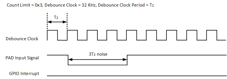
GPIO Debounce Function Illustration 1
When the PAD input signal is \(>= 4T_2\), it is regarded as a valid signal. However, it is important to note that there is a fixed delay of \(2T_2\) from the PAD input signal to the debounce output signal. Therefore, the actual time at which the GPIO interrupt is triggered will consistently have a delay of \(2T_2\).
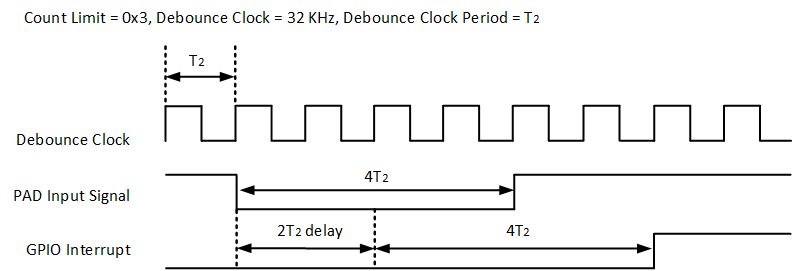
GPIO Debounce Function Illustration 2
Troubleshooting
GPIO False Trigger Interrupt
GPIO edge-type interrupts will be self-triggered when enabling the GPIO interrupt in the following four modes:
PAD input = high, rising edge triggered interrupt.
PAD input = high, double edge triggered interrupt.
PAD input = low, falling edge triggered interrupt.
PAD input = low, double edge triggered interrupt.
The below flow can be used to enable edge interrupt in these cases to avoid self-triggered interrupt:
Mask GPIO interrupt:
GPIO_MaskINTConfig(GPIO_PORT, GPIO_PIN, ENABLE).Enable edge interrupt:
GPIO_INTConfig(GPIO_PORT, GPIO_PIN, ENABLE).Clear GPIO interrupt state:
GPIO_ClearPendingBit(GPIO_PORT, GPIO_PIN).Unmask GPIO interrupt:
GPIO_MaskINTConfig(GPIO_PORT, GPIO_PIN, DISABLE).
The following flow can modify the GPIO interrupt configurations to avoid self-triggered interrupt:
Mask GPIO interrupt:
GPIO_MaskINTConfig(GPIO_PORT, GPIO_PIN, ENABLE).Modify GPIO interrupt configurations (change interrupt trigger edge and polarity):
GPIO_SetITTrigger(GPIO_PORT, GPIO_PIN, GPIO_TriggerMode)GPIO_SetITPolarity(GPIO_PORT, GPIO_PIN, GPIO_ITPolarity)....Clear GPIO interrupt state:
GPIO_ClearPendingBit(GPIO_PORT, GPIO_PIN).Unmask GPIO interrupt:
GPIO_MaskINTConfig(GPIO_PORT, GPIO_PIN, DISABLE).