IR Receive
This sample demonstrates how to receive data in IR interrupt mode.
Use the P2_6 pin as a PWM output pin, outputting a PWM waveform to simulate sender data. Connect the PWM output pin to the IR input pin.
Data reception occurs within the IR interrupt. When the data volume exceeds the IR FIFO capacity, multiple consecutive data receptions are required.
Requirements
For requirements, please refer to the Requirements.
Wiring
Connect the PWM output pin P2_6 to the IR receiver pin P2_5.
Configurations
-
The following macro can be configured to modify the pin definitions.
#define IR_RX_PIN               P2_5
#define PWM_OUT_PIN             P2_6
-
The following macros can be configured to modify PWM configuration information.
#define PWM_PERIOD              26.3   //uint:us
#define PWM_DUTY_CYCLE          50     //uint:percent
#define PWM_HIGH_COUNT          ((((PWM_PERIOD)*(PWM_DUTY_CYCLE*40))/100)-1)
#define PWM_LOW_COUNT           ((((PWM_PERIOD)*((100-PWM_DUTY_CYCLE)*40))/100)-1)
Building and Downloading
For building and downloading, please refer to the Building and Downloading.
Experimental Verification
After initialization is complete, the PWM begins to output waveforms with a frequency set to 38KHz, matching the IR reception frequency. In the main function, the TIM PWM output is repeatedly enabled and disabled every 500 microseconds to simulate 500 microseconds of data with and without a carrier. The PWM waveform is as shown in the diagram.
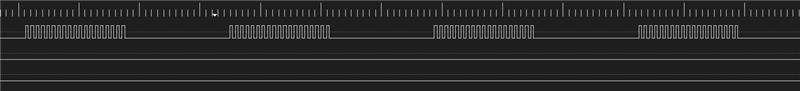
PWM output waveform
When the PWM outputs a waveform, the IR receiver interprets the 500 microsecond PWM waveform as a mark data. When the PWM does not output a waveform, the IR receiver interprets the 500 microseconds of low level as a space data.
When the number of data counted by the IR receiver reaches the set threshold, it triggers the IR
IR_INT_RF_LEVELinterrupt, and the current data is received within the IR interrupt.-
In the main program, after the PWM output changes several times, it will stop outputting the PWM waveform, at which point the IR detects a low level input. When the low level input time reaches the preset counter value, it triggers the
IR_INT_RX_CNT_THRinterrupt, and all remaining data is received.IR_INT_RX_CNT_THR len = xx [io_ir]io_handle_ir_msg: IR RX data[0] = 0x80000012 [io_ir]io_handle_ir_msg: IR RX data[1] = 0x00000012 ... [io_ir]io_handle_ir_msg: IR RX data[xx] = 0x00000200
Note
The carrier data 0x800000012 indicates a high-level output for 12 carrier cycles, and 0x12 represents a low-level output for 12 carrier cycles.
Code Overview
This section introduces the code and process description for initialization and corresponding function implementation in the sample.
Source Code Directory
The directory for project file and source code are as follows:
Project directory:
sdk\samples\peripheral\ir\rx\projSource code directory:
sdk\samples\peripheral\ir\rx\src
Initialization
The initialization flow for peripherals can refer to Initialization Flow in General Introduction.
-
Call
Pad_Config()andPinmux_Config()to configure the PAD and PINMUX of the corresponding pins.void board_ir_init(void) { Pad_Config(IR_RX_PIN, PAD_PINMUX_MODE, PAD_IS_PWRON, PAD_PULL_NONE, PAD_OUT_DISABLE, PAD_OUT_LOW); Pinmux_Config(IR_RX_PIN, IRDA_RX); } void board_pwm_init(void) { Pad_Config(PWM_OUT_PIN, PAD_PINMUX_MODE, PAD_IS_PWRON, PAD_PULL_NONE, PAD_OUT_ENABLE, PAD_OUT_HIGH); Pinmux_Config(PWM_OUT_PIN, PWM_OUT_PIN_PINMUX); }
Call
RCC_PeriphClockCmd()to enable the IR clock.-
Initialize the IR peripheral:
Define the
IR_InitTypeDeftypeIR_InitStruct, and callIR_StructInit()to pre-fillIR_InitStructwith default values.Modify the
IR_InitStructparameters as needed. The IR initialization parameter configuration is shown in the table below.Call
IR_Init()to initialize the IR peripheral.
IR Hardware Parameters |
Setting in the |
IR |
|---|---|---|
Sample Clock |
38000 |
|
IR Mode |
||
IR Rx Mode |
||
FIFO Threshold Level |
10 |
|
IR Rx Trigger Mode |
||
IR Rx Counter Threshold Type |
||
IR Rx Counter Threshold |
0x200 |
Call
IR_Cmd()to enable the IR peripheral.Call
IR_INTConfig()andIR_MaskINTConfig()to configure the IR receive FIFO data count greater than the set receive threshold interruptIR_INT_RF_LEVELand the receive level timeout interruptIR_INT_RX_CNT_THR. Configure NVIC, for details refer to Interrupt Configuration.Call
RCC_PeriphClockCmd()to enable the TIM clock.-
Initialize the TIM peripheral:
Define the
TIM_TimeBaseInitTypeDeftypeTIM_InitStruct, and callTIM_StructInit()to pre-fillIR_InitStructwith default values.Modify the
TIM_InitStructparameters as needed. The TIM initialization parameter configuration is shown in the table below.Call
TIM_TimeBaseInit()to initialize the TIM peripheral.
TIM Hardware Parameters |
Setting in the |
TIM |
|---|---|---|
TIM Mode |
||
PWM Enable |
||
PWM High Count |
|
|
PWM Low Count |
|
Functional Implementation
The flow of receiving data via IR through interruption is shown in the figure:
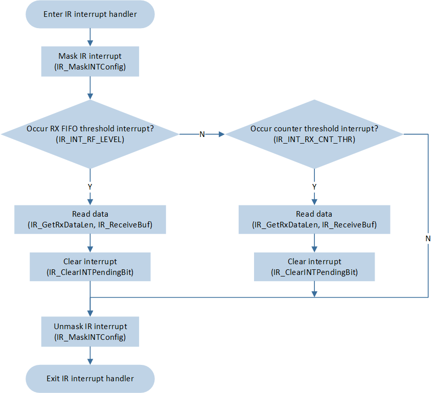
IR receive data through interrupt flow
In
ir_demo, the loop enables and disables PWM output to simulate IR carrier data. After 50 cycles, the PWM will stop outputting the waveform.
void ir_demo(void)
{
    ...
    for (uint32_t i = 0; i < 50; i++)
    {
        TIM_Cmd(PWM_TIMER_NUM, ENABLE);
        platform_delay_us(500);
        TIM_Cmd(PWM_TIMER_NUM, DISABLE);
        platform_delay_us(500);
    }
}
When the number of data in the IR receive FIFO reaches the set receive threshold, it triggers the
IR_INT_RF_LEVELinterrupt. Within the interrupt, callIR_GetRxDataLen()andIR_ReceiveBuf()to receive the current IR data.-
After the PWM stops outputting the waveform, when the IR detects a low-level duration exceeding the set carrier cycle of
IR_InitTypeDef::IR_RxCntThr, it triggers theIR_INT_RX_CNT_THRinterrupt. Within the interrupt, callIR_GetRxDataLen()andIR_ReceiveBuf()to receive the remaining IR data.void IR_Handler(void) { uint16_t len = 0; ITStatus int_status_rfl = IR_GetINTStatus(IR_INT_RF_LEVEL); ITStatus int_status_rxcnt = IR_GetINTStatus(IR_INT_RX_CNT_THR); /* Mask IR all interrupt */ IR_MaskINTConfig(IR_INT_RF_LEVEL | IR_INT_RX_CNT_THR, ENABLE); /* Receive by interrupt */ if (int_status_rfl == SET) { len = IR_GetRxDataLen(); IR_ReceiveBuf(IR_Rx_Data.DataBuf + IR_RX_Count, len); IR_Rx_Data.DataLen += len; IR_RX_Count += len; IR_ClearRxFIFO(); IR_ClearINTPendingBit(IR_INT_RF_LEVEL_CLR); } /* Stop to receive IR data */ if (int_status_rxcnt == SET) { DBG_DIRECT("IR_INT_RX_CNT_THR"); /* Read remaining data */ len = IR_GetRxDataLen(); IR_ReceiveBuf(IR_Rx_Data.DataBuf + IR_RX_Count, len); IR_Rx_Data.DataLen += len; IR_RX_Count += len; ... memset(&IR_Rx_Data, 0, sizeof(IR_Rx_Data)); IR_RX_Count = 0; IR_ClearINTPendingBit(IR_INT_RX_CNT_THR_CLR); } /* Unmask IR all interrupt */ IR_MaskINTConfig(IR_INT_RF_LEVEL | IR_INT_RX_CNT_THR, DISABLE); }
See Also
Please refer to the relevant API Reference: