Quick Start
This document aims to guide users in quickly setting up the development environment for RTL8773EWE/RTL8773EWE-VP/RTL8773EWE-VS, including compiling the SDK, downloading firmware, updating firmware, and capturing logs. Users can download the test files in the SDK to ensure that the EVB can work normally and is compatible with the development environment while possessing corresponding functions.
Overview
Users can compile the projects in the SDK via Keil, use MPPG Tool to download the files into the EVB, and then capture SoC logs via Debug Analyzer. Hardware wiring configurations and corresponding PC software architecture can refer to EVB Working Principle Diagram.
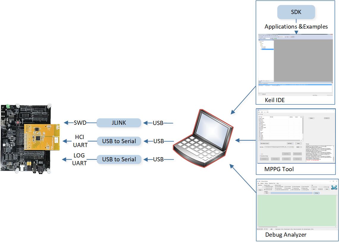
EVB Working Principle Diagram
Prepare EVB
The EVB provides users with the Hardware Environment for development and application debugging. It includes the RTL8773E evaluation motherboard, RTL8773EWE/RTL8773EWE-VP/RTL8773EWE-VS evaluation daughterboard, and requires several function daughter boards to implement the features in the SDK. Users need to prepare a USB data cable to connect the EVB and the PC. For the EVB's peripheral interface wiring, please refer to EVB Interface Distribution Diagram.
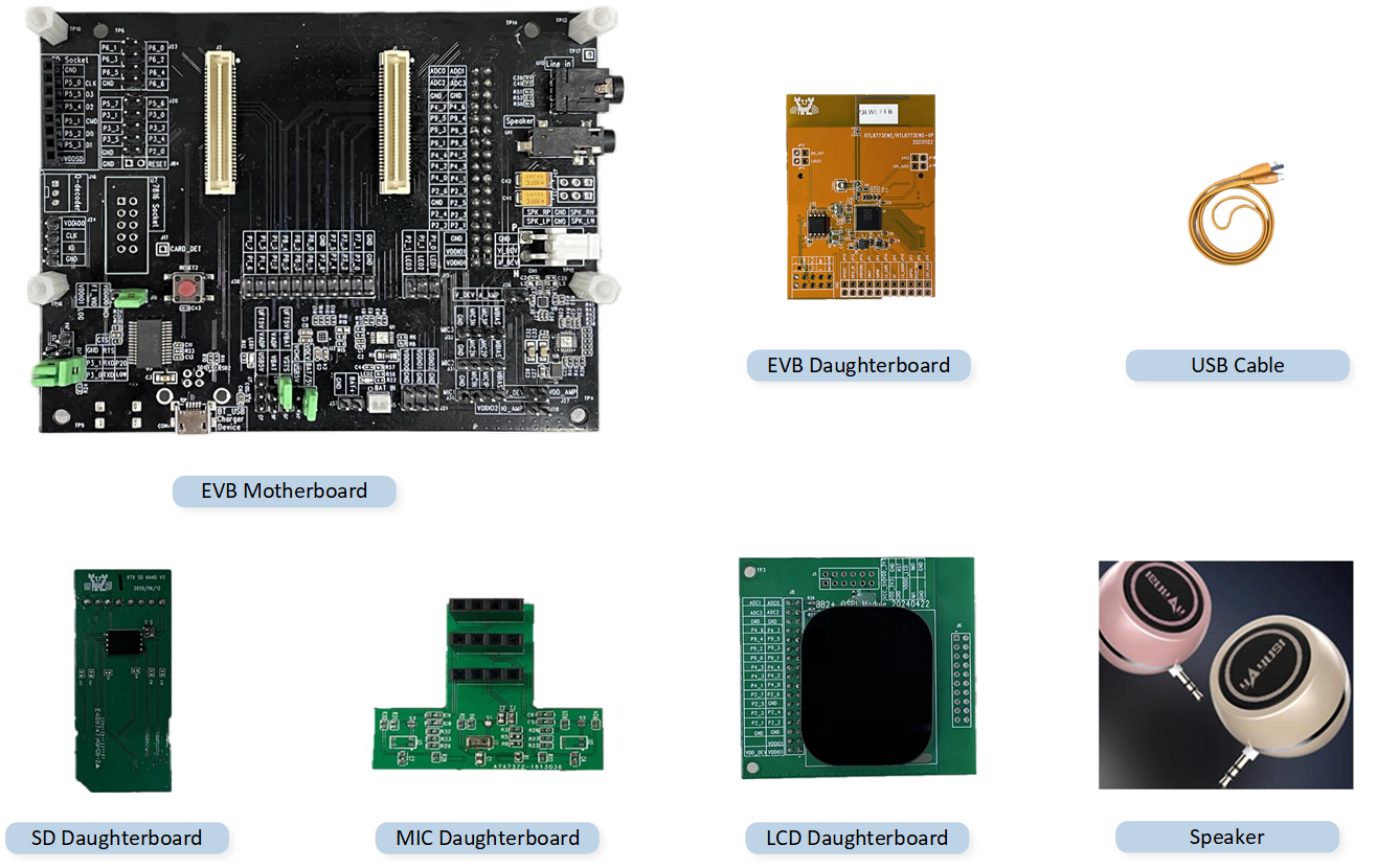
Hardware Environment
Prepare Files
The normal operation of the EVB requires downloading the following files.
Basic Files: Including the firmware and configuration files required by the RTL8773EWE/RTL8773EWE-VP/RTL8773EWE-VS.
Application Files: Including the specific code and function implementations of the target project.
Below are the Default Files required for the normal operation. File explanations can be referred to in the Building and Downloading chapter.
File |
Provided by Realtek |
File Category |
RTL8773EWE/RTL8773EWE-VP Default Path |
RTL8773EWE-VS Default Path |
|---|---|---|---|---|
System Config File |
(Generated by MCUConfig Tool) |
|
|
|
Boot Patch0 Image |
√ |
Basic File |
|
|
Boot Patch1 Image |
√ |
Basic File |
|
|
Platform EXT Image |
√ |
Basic File |
|
|
BT Controller EXT Image |
√ |
Basic File |
|
|
BT Host File |
√ |
Basic File |
|
|
OTA Header File |
(Generated by MPPG Tool) |
Basic File |
|
|
Stack Patch Image |
√ |
Basic File |
|
|
System Patch Image |
√ |
Basic File |
|
|
APP Image |
(Generated by Project Compilation) |
Application File |
|
|
DSP SYS Image |
√ |
Basic File |
|
|
DSP APP Image |
√ |
Basic File |
|
|
DSP Config Image |
(Generated by DSPConfig Tool) |
Basic File |
|
|
APP Config File |
(Generated by MCUConfig Tool) |
Basic File |
|
|
VPData Config File |
(Generated by MCUConfig Tool) |
Basic File |
|
|
User Data File |
(Merged from Font Library and Image Resources) |
Basic File |
|
|
Software Tools
During the development of the SDK, users need to use Realtek's development toolkit and ARM development suite. Please refer to the following table.
Tools |
Links/Paths |
Version |
OS |
|---|---|---|---|
ARM Keil MDK |
uVision: V5.36 ARMCC: V5.06 update 6 (build 750) |
Win 10 |
|
MPPG Tool |
|
Win 10 |
|
MCUConfig Tool |
|
Win 10 |
|
Debug Analyzer |
|
Win 10 |
|
DSPConfig Tool |
|
Win 10 |
|
Font Convert Tool |
|
Win 10 |
|
Image Converter Tool |
|
Win 10 |
|
Android OTA APP |
|
Android |
|
iOS OTA APP |
|
iOS |
|
Android Audio Connect |
|
Android |
|
iOS Audio Connect |
|
iOS |
Note
Installation packages under the path are in
.zipformat, users need to decompress themselves.
ARM Keil MDK
Users can compile applications in the SDK through Keil Microcontroller Development Kit(MDK). For more information, please refer to Keil MDK section.
MPPG Tool
Users can use the MPPG Tool to download files. The MPPG Tool offers two downloading modes: MP and Debug. The mass production mode is suitable for large-scale production. This article mainly describes the Debug Mode at MPPG Tool Download, which is intended for developers in the early stages of software development. For more information, consult the MPPG Tool User Guide in the SDK.
MCUConfig Tool
Users can change configuration files through the MCUConfig Tool. By importing RTL8773EWE.rcfg/RTL8773EWE-VP.rcfg, modifying the configuration, and exporting,
they can regenerate the APP Config File, System Config File, and VPData Config File.
For more information, consult the MCUConfig Tool User Guide in the SDK.
Debug Analyzer
Users can capture the SoC logs through Debug Analyzer. For more information, please refer to the Debug Analyzer User Guide in the SDK.
DSPConfig Tool
DSPConfig allows developers to configure built-in signal processing algorithm parameters for various scenarios such as phone calls and music playback. Additionally, this tool provides user-friendly parameter fine-tuning capabilities and supports the generation of DSP configuration images, significantly reducing the time required for parameter optimization. For detailed instructions on how to use the DSPConfig tool, please refer to the user guide included with the tool.
Font Conversion Tool
Users can generate font library files through the Font Convert Tool. For more information, please refer to the Font Conversion Tool .
Image Converter Tool
Users can generate image resource files through the Image Converter Tool. For more information, please refer to the Image Conversion Tool .
Android OTA Tool
The Android OTA Tool is used to upgrade the firmware of Realtek chips through Android. For more information, please refer to the Android OTA App User Guide in the SDK.
iOS OTA Tool
The iOS OTA Tool is used to upgrade the firmware of Realtek chips through iOS. For more information, please refer to the iOS OTA APP User Manual in the SDK.
Android Audio Connect
Android Audio Connect integrates some audio-related functions. The watch application mainly uses LocalPlayback for transferring Android files. For more information, please refer to the Android Audio Connect App User Guide.
iOS Audio Connect
LocalPlayback in iOS Audio Connect is used for iOS file transfer.
Bring Up EVB
To ensure the EVB functions correctly, users can follow these steps for downloading and testing:
Prepare an EVB, confirm that the connections at the EVB Interface are correct, switch the EVB to Download Mode, and power on the EVB.
-
Double-click to run MPPG Tool.exe, and use MPPG Tool to download the EVB with the Default Files.
Click the open file icon in the Flash Map to load the
flash_map.inifile.Click Add File(s) to load all Default Files.
Click Detect to successfully identify the COM port of the EVB.
Click Open to successfully open the COM port.
Click Download to start flashing, and the progress bar will show the current flashing progress.
Progress bar display Success indicates that the file download is successful.
After the downloading is complete, let the EVB enter Normal Mode.
Observe the behavior of the EVB, which can be verified through LCD interface display Verification or by checking SoC log Verification to see if it meets the expectations.
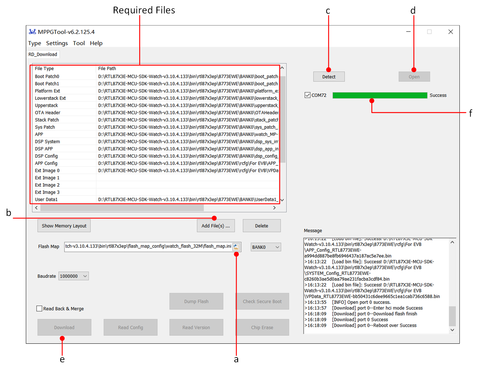
MPPG Tool Download Interface
Note
Please store SDK, Tool and other materials under a non-Chinese path without spaces.
During download, only erase what is necessary for the download. If fully erasing the Flash is needed, click Chip Erase before downloading.
Hardware Development Environment
The EVB provides a Hardware Environment for user development and application debugging. It consists of a main board and a sub-board. The EVB has Download Mode and Working Mode, and users need to use different connection methods to set the correct mode.
EVB Interfaces and Modules
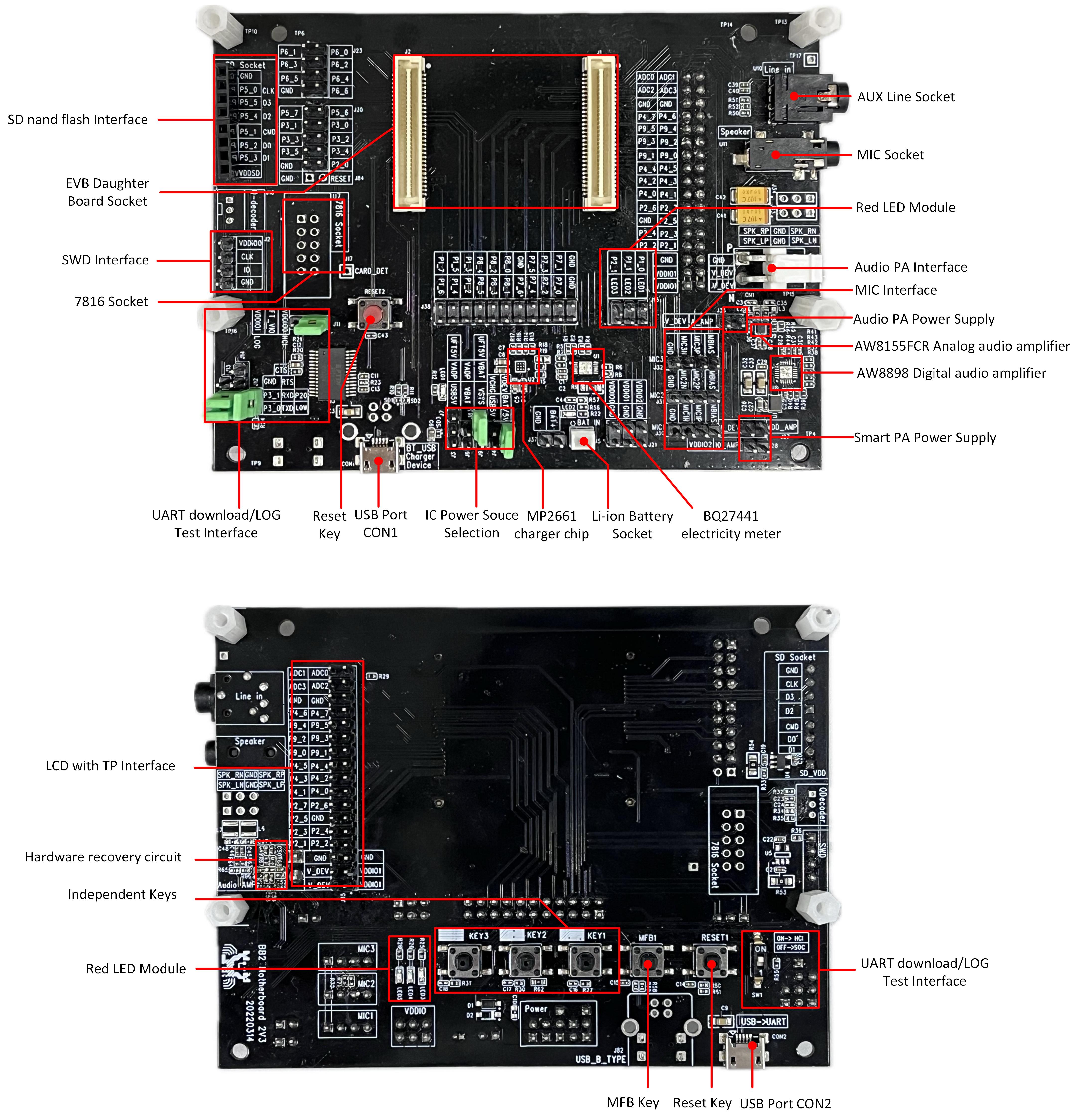
EVB Interface Distribution Diagram
Note
This section aims to provide a quick start. For detailed documentation on the evaluation board hardware, please refer to the EVB Guide.
Power Supply
Power the EVB via the USB port on CON2 connected to the computer, or via a 3.7 V battery.
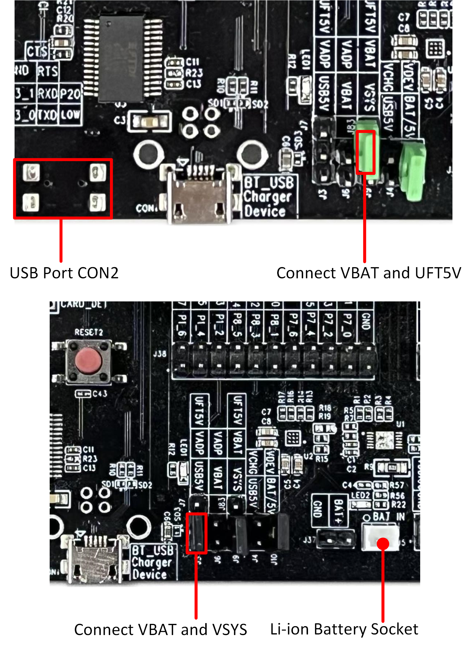
EVB Power Supply Wiring
Log Wiring
On the front side of the EVB, there is a dial switch. Turn the switch to the '1' position. Connect the RX and LOG using jumper wires. After completing the connection, check if the SoC log meets the expectations.
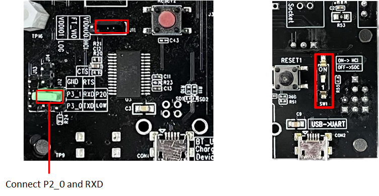
Log Wiring
Download Mode
Before powering up the EVB, the user needs to ground the Log Pin (default P2_0). There are two methods to do this:
Method One: Connect the jumper to J12 to ground P2_0.
Method Two: Set the dip switch on the front of the EVB to 'ON' to indicate Log ground.
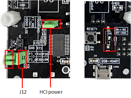
Grounding Log Pin Method
After EVB enters download mode, use the MPPG Tool to download.
Note
After powering on, the chip will read the level signal of the Log Pin. If the level is low, the Bypass Flash will enter download mode; otherwise, it will enter working mode and run the application layer program.
Normal Mode
For the EVB to function properly, set the front dip switch to '1' and disconnect Log and GND.
Building and Downloading
The following describes the Default Files :
Serial Number |
File Name |
Description |
|---|---|---|
1 |
System Config File |
Used to record IC hardware configurations and Bluetooth settings such as configuring BT addresses, modifying the number of links, and DSP configuration files. These can be reconfigured and generated using the MCUconfig Tool. |
2 |
Boot Patch Image |
Contains two files: Boot Patch0 Image and Boot Patch1 Image. The ROM code retains a patch function entry, which can optimize the boot process, modify the original behavior of secure ROM code, and extend ROM code functions, among other things. |
3 |
Platform EXT Image |
Extends the platform code. |
4 |
BT Controller EXT Image |
Extends the Bluetooth Controller protocol stack. |
5 |
BT Host File |
Bluetooth Host protocol stack file. |
6 |
OTA Header File |
Defines the Flash Bank layout. |
7 |
BT Stack Patch Image |
Support file for stack-related features in the Bluetooth Controller. |
8 |
System Patch Image |
The ROM code retains a patch function entry, which can modify the original behavior of non-secure ROM code and extend ROM code functions, among other things. |
9 |
APP Image |
Application file generated by developers using Keil compilation. |
10 |
DSP SYS Image |
DSP system file. |
11 |
DSP APP Image |
DSP application file. |
12 |
DSP Config Image |
DSP configuration file, which can be reconfigured and generated using the DSPConfig Tool. |
13 |
APP Config File |
Contains information such as device name and address configuration, which can be reconfigured and generated using the MCUConfig Tool. |
14 |
VPData Config File |
Configuration file for voice prompts and ringtones, which can be reconfigured and generated using the MCUConfig Tool. |
15 |
User Data bin |
Contains GUI resources required by users in the MCU, mainly including images and fonts. This bin file is closely related to the display effects on the screen. |
Note
Please store the SDK and related materials in a path that does not contain spaces or Chinese characters.
Generate Flash Map
The Flash map file is the user's plan for the distribution of the entire flash space. Users can reallocate the flash space by following the steps below.
If no parameters need to be modified, this section can be skipped.
The default flash map provided by the SDK is located at bin\rtl87x3ep\flash_map_config\watch_flash_32M\flash_map.ini.
In the Tool options of the MPPG Tool, click FlashMapGenerator to enter the FlashMapGenerator interface.
Users can click on Import... to import and modify the default
flash_map.inifile.Click the dropdown: Flash Size option. Users can select the appropriate Flash Size based on the actual usage of the Flash.
Click Layout Init, where users can modify the Flash Layout independently based on actual requirements and adjust the size of each area.
After confirming, click Confirm.
After the configuration is completed, click Generate... to generate a
flash_map.inifile. Aflash_map.hfile will also be generated simultaneously.
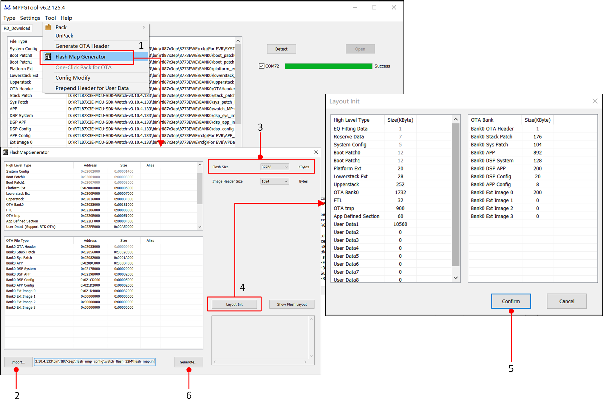
Flash Map Generate Tool
Note
After adjusting the flash map, update the corresponding OTA Header and MCU config file.
In the FlashMapGenerator, modify the attribute of whether the User Data file supports OTA.
Generating OTA Header
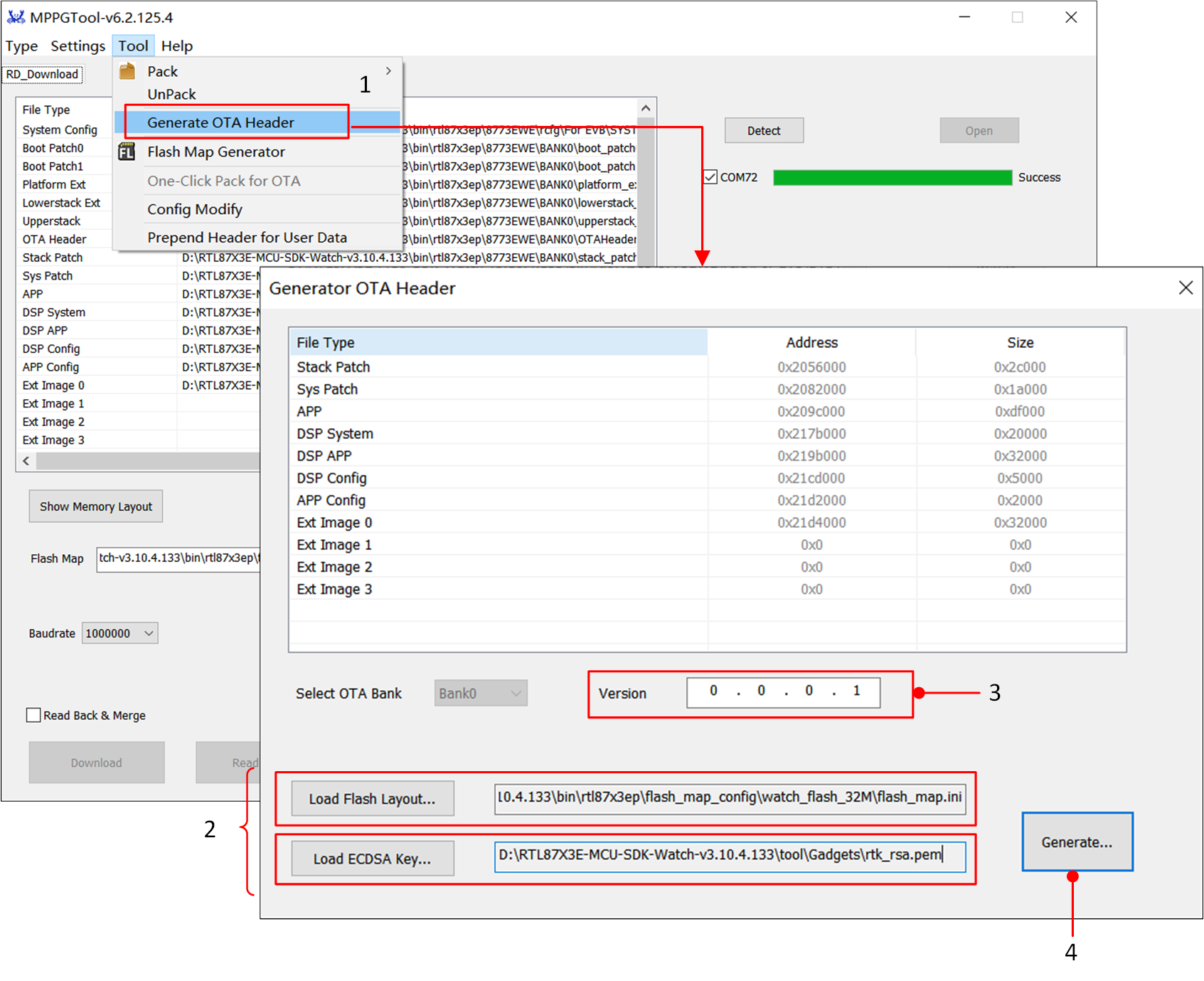
BootLoader will read the layout distribution of each Image based on the OTA Header file. In the Tool option of the MPPG Tool, click Generate OTA Header to enter the Generate OTA Header interface, where it is possible to regenerate the OTA Header.
First, load the flash_map.ini (e.g., bin\rtl87x3ep\flash_map_config\watch_flash_32M\flash_map.ini) and the ECDSA key (e.g., tool\Gadgets\ecdsa_key.pem).
Then, the user can modify the version number information.
Finally, click Generate, and the OTA Header File will be generated.
If no parameters need to be changed, skip this section. The default OTA Header provided by the SDK is located at bin\rtl87x3ep\8773EWE\BANK0\OTAHeader_Bank0_vx.x.x.x.bin.
OTA Header File
Note
If the Flash Layout is modified, the OTA Header File will also be updated. Please ensure the consistency between the flash_map.ini and the OTA Header File.
Generate MCU Config File
Users can generate MCU Config files using the MCUConfig Tool, allowing them to change certain application settings and system behaviors without modifying the source code. This includes the APP Config File, System Config File, and VPData Config File.
Next, a brief introduction to the generation steps: Users can customize modifications based on the default rcfg provided by the Realtek SDK. For specific specifications of the MCUConfig Tool, refer to the MCUConfig Tool User Guide.
If there are no parameters that need modification, skip this section and directly use the MCU Config file in the SDK located at bin\rtl87x3ep\8773EWE\rcfg.
Double-click to open McuConfigTool.exe, select the corresponding chip, then click Import Bin File and load the default rcfg from the SDK, as shown in the path in the figure.
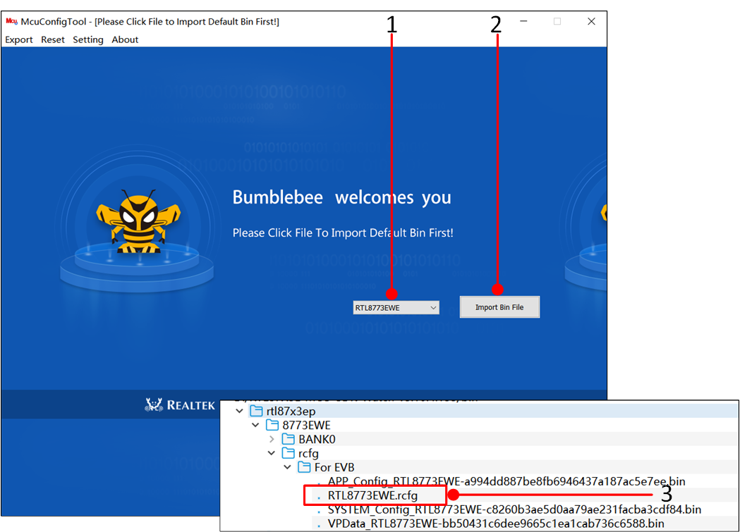
Use MCUConfig Tool To Import File
Users can modify the configuration in the corresponding fields according to project requirements, and after completion, click the Export button. There are two options: one is Save as, which allows users to directly export the MCU config bin of the corresponding chip; the other is RTL8773EWE To RTL8773EWE_VP, which allows users to save the configuration of the RTL8773EWE chip as the configuration of the RTL8773EWE_VP chip, facilitating project migration.
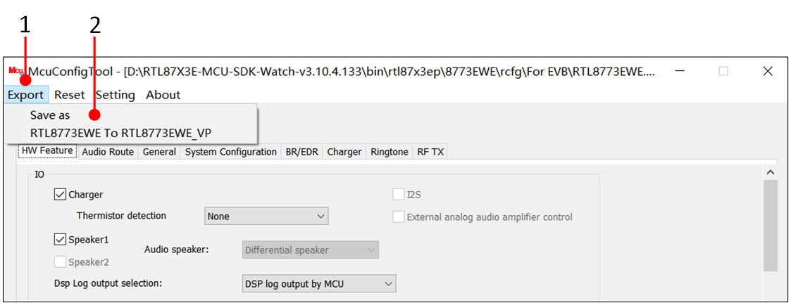
Use MCUConfig Tool To Export Files
Note
During the configuration process, if a re-import of the rcfg is desired, click the Reset button under the Reset all data interface and return to the main interface to reselect.
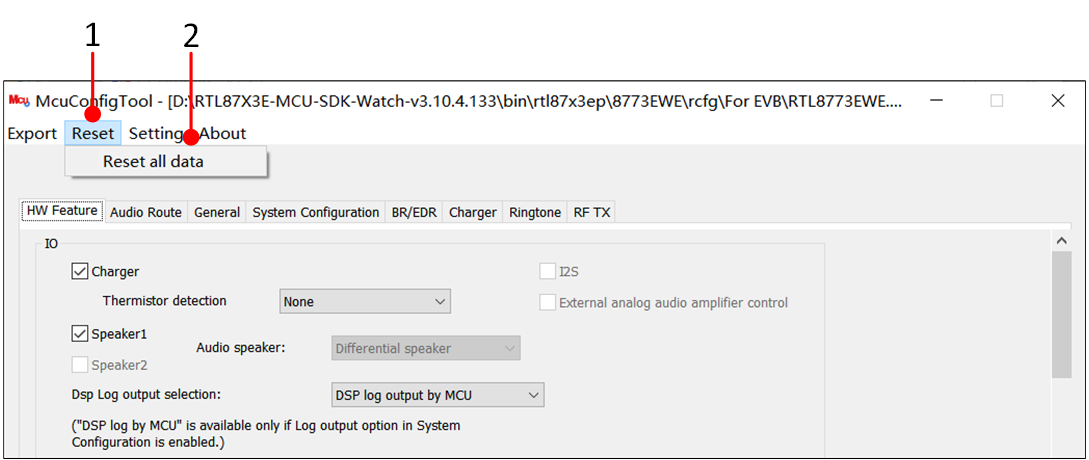
Reset The Current File In MCUConfig Tool
The MCUConfig tool requires importing the
flash_map.inifile. Whenever there are changes to the Flash Layout, it is necessary to regenerate the MCU config file.
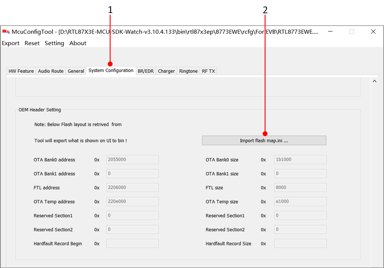
Loading flash_map.ini
Currently RTL8773EWE-VS can be imported using RTL8773EWE IC type, just note the difference between
flash_map.ini.
Generate User Data
Users can store images, font libraries, and other information together in the Userdata. The process for synthesizing can be referenced at Packaging Steps. Finally, an MP header needs to be added to this file. The steps are as follows:
In the Tool options of the MPPG Tool, click Prepend Header for User Data to enter the Prepend Header for User Data screen.
Click on the open file icon and import the corresponding
flash_map.inifile.Load the bin file to which the MP header is to be added in the File Path.
Click Generate... to create User Data with the added MP header, which can be downloaded using the MPPG tool.
If the default User Data provided by the SDK is used, this chapter can be skipped and bin\rtl87x3ep\8773EWEBANK0\User_Data1_MP.bin can be directly used.
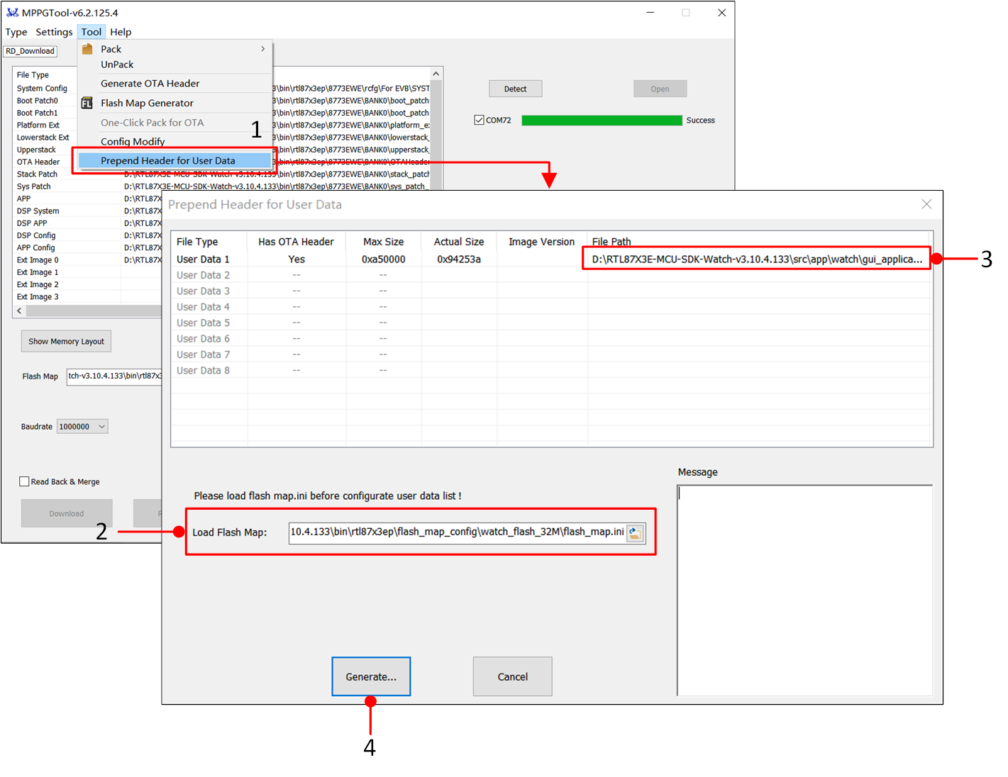
Adding MP Header For User Data
Compile APP Image
All applications within the SDK can be compiled and used through Keil MDK. Before proceeding with software development, the Keil compilation environment must be installed. To facilitate the quick establishment of development projects, users can copy or directly open existing example projects and add functional code based on these.
Keil MDK
Keil MDK is a comprehensive software development environment suited for various Arm Cortex-M based microcontroller devices. MDK includes the µVision integrated development environment and debugger, the Arm C/C++ compiler, as well as essential middleware components.
All applications in the SDK can be compiled and used through Keil MDK. Therefore, before starting software development, make sure to obtain and install Keil. For more information about Keil, please visit www.keil.com .
The toolchain version information used by Realtek is shown in the figure. To avoid compatibility issues between ROM executables and applications, it is recommended to use uVision V5.36 or a newer version and configure the ARMCLANG default compiler as ARMCC_506build750.
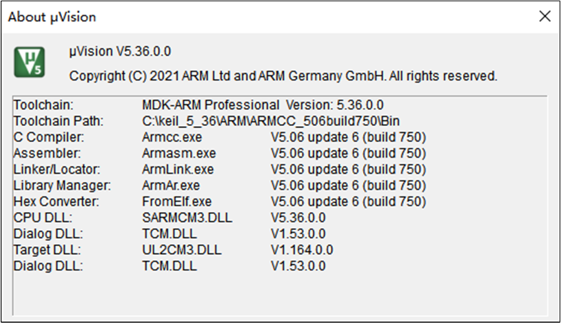
Keil Version Information
The steps to configure the default compiler to ARMCC_506build750 are as follows.
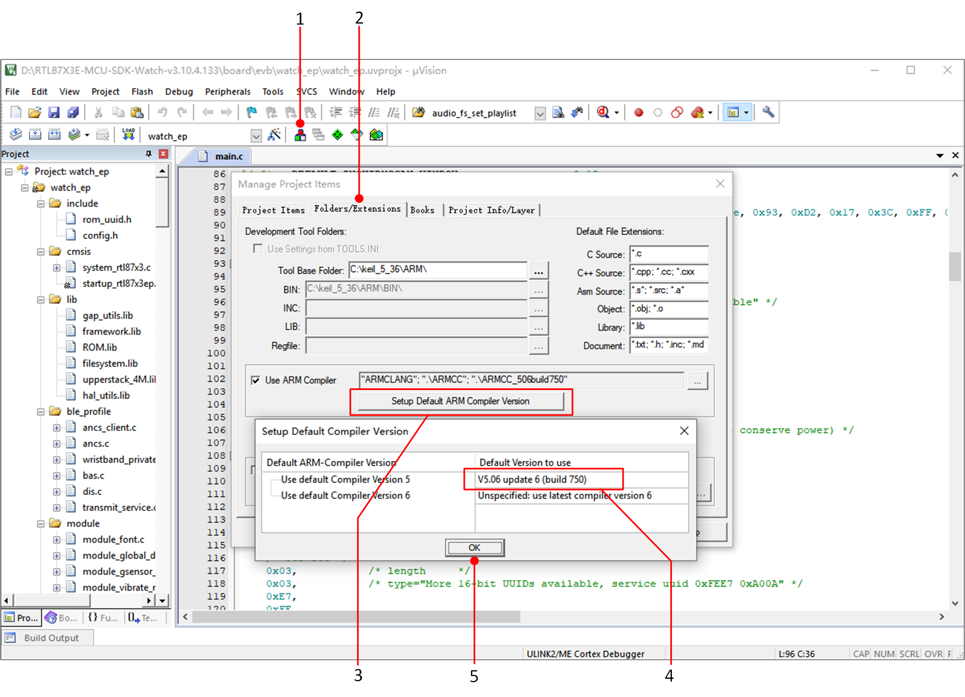
Keil Compiler Version Configuration
Using the watch_ep project as an example, after a successful compilation, a bin file with an MD5 checksum will be generated in the project's bin folder, along with corresponding .trace files.
The .trace file is used to parse SoC side logs.
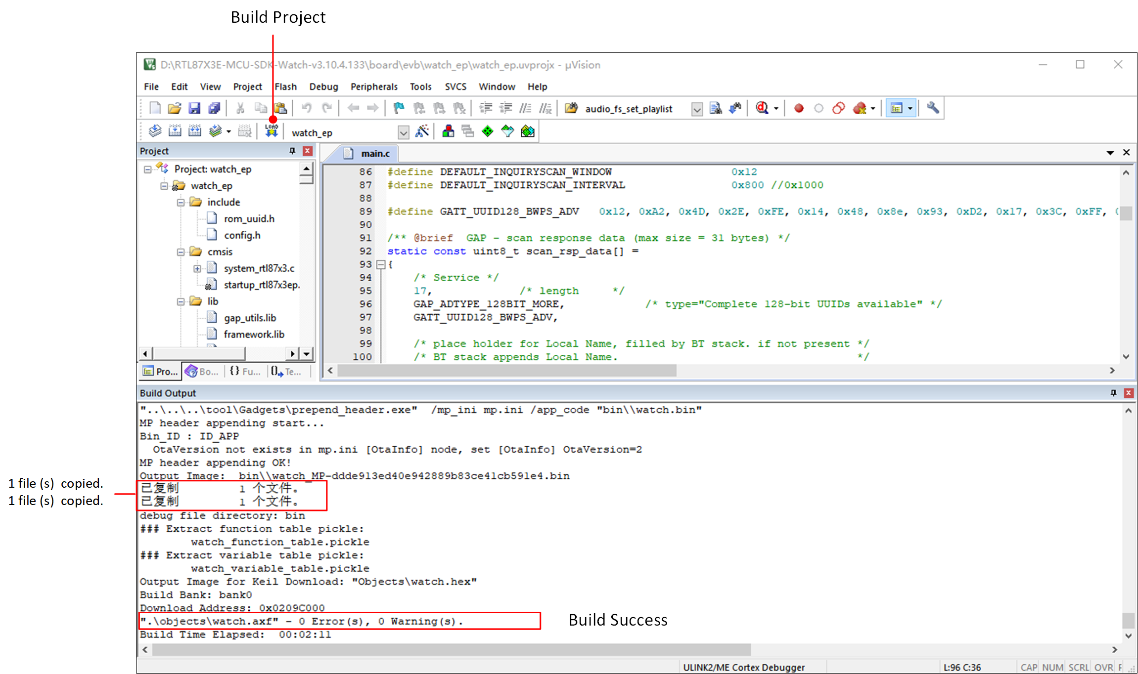
Compile The watch_ep Project
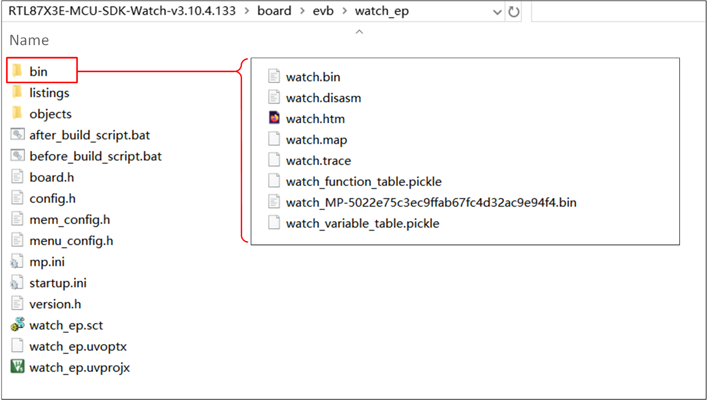
Files Generated by Project Compilation
Note
The MPPG Tool uses MD5 as the checksum for files and requires the MD5 value to be appended to the file name suffix of the file to be programmed, so the programmed file will have the prefix 'MP' in its APP Image.
Download File
MPPG Tool Download
Users can download files to the device using the MPPG Tool. Detailed instructions on how to use the MPPG Tool can be found in the SDK User Guide.
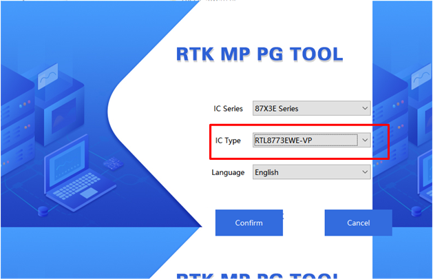
MPPG Tool Chip Selection
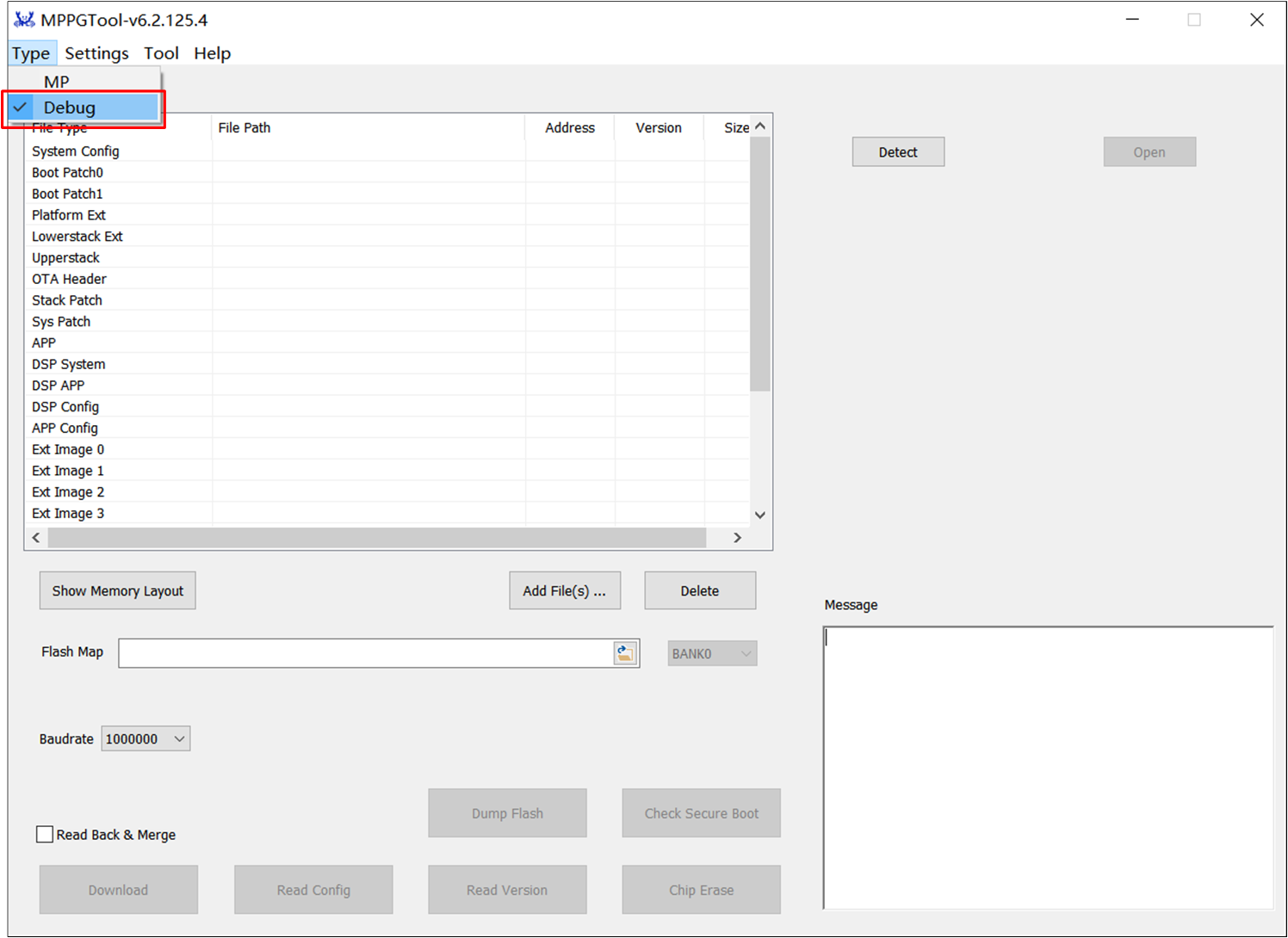
MPPG Tool Mode Selection
After correctly selecting the chip model and mode, load all the default files. The loading steps are described in the section on Bring Up EVB.
Common mistakes are as follows
Check if the serial port Tx/Rx is reversed, and ensure the cabling is not too long or thin.
Check if the device Log Pin is grounded before powering up.
Check if the COM port is in use.
Avoid using low-quality USB cables; if using a USB HUB, try connecting directly to the computer's USB port.
Use an authentic serial port board, such as FT232; avoid using CP2102.
After the download is complete, it will display 'Success'. If it displays 'Fail', press the Reset button on the EVB or power cycle the EVB and repeat the steps above.
Note
MPPG Tool supports two downloading modes:
MP Mode: Used for production lines.
Debug Mode: For use by developers during development and debugging.
J-Link Download
J-Link is a debugger/simulator developed by SEGGER. It is a dedicated tool for ARM processors, used for firmware development, debugging, and testing on embedded devices. It provides high-speed and reliable simulation performance, supporting real-time debugging and quick firmware downloads. J-Link helps developers accelerate the debugging and verification process of embedded systems, improving development efficiency and quality.
Additionally, J-Link is compatible with multiple development environments and IDE, such as Keil MDK, IAR Embedded Workbench, etc. It is recommended to use J-Link software v6.44 (or a higher version).
J-Link supports various connection interfaces, such as JTAG, SWD, etc. Since SWD requires fewer connections, RTL87x3 adopts this interface. More information can be found in SWD debugging.
After completing the SWD connection, users can download application program images via J-Link. Please ensure that other images have already been downloaded using MPPG Tool. Then users can use J-Link to download.
Note
SWD is more suitable for debugging external IO drivers and platform-related issues, but not recommended for debugging Bluetooth-related applications. This may disrupt the normal state of Bluetooth and lead to lower debugging efficiency. Therefore, it is recommended to use Debug Analyzer.
Example Verification
LCD Interface Display Verification
After download, let the EVB enter normal mode, and after resetting the motherboard, the screen interface will display the dashboard interface. The following figure shows an example of a 454*454 circular screen.
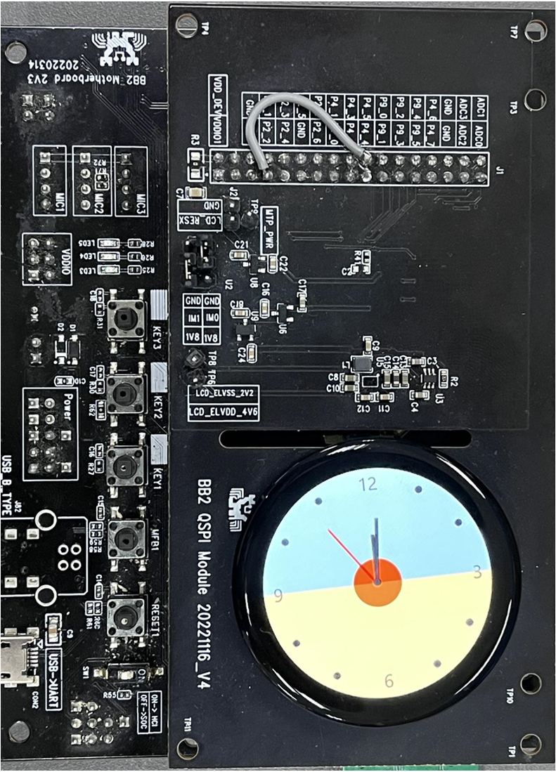
LCD Interface Display
Log Verification
Users can capture the SoC-side log via Debug Analyzer to confirm if the program is running correctly. Please properly complete Log Wiring.
Double-click DebugAnalyzer.exe, click Setting, set the Baud rate to the default 2M, load the corresponding project's .trace file at App Trace File,
and finally click Confirm to apply the settings.
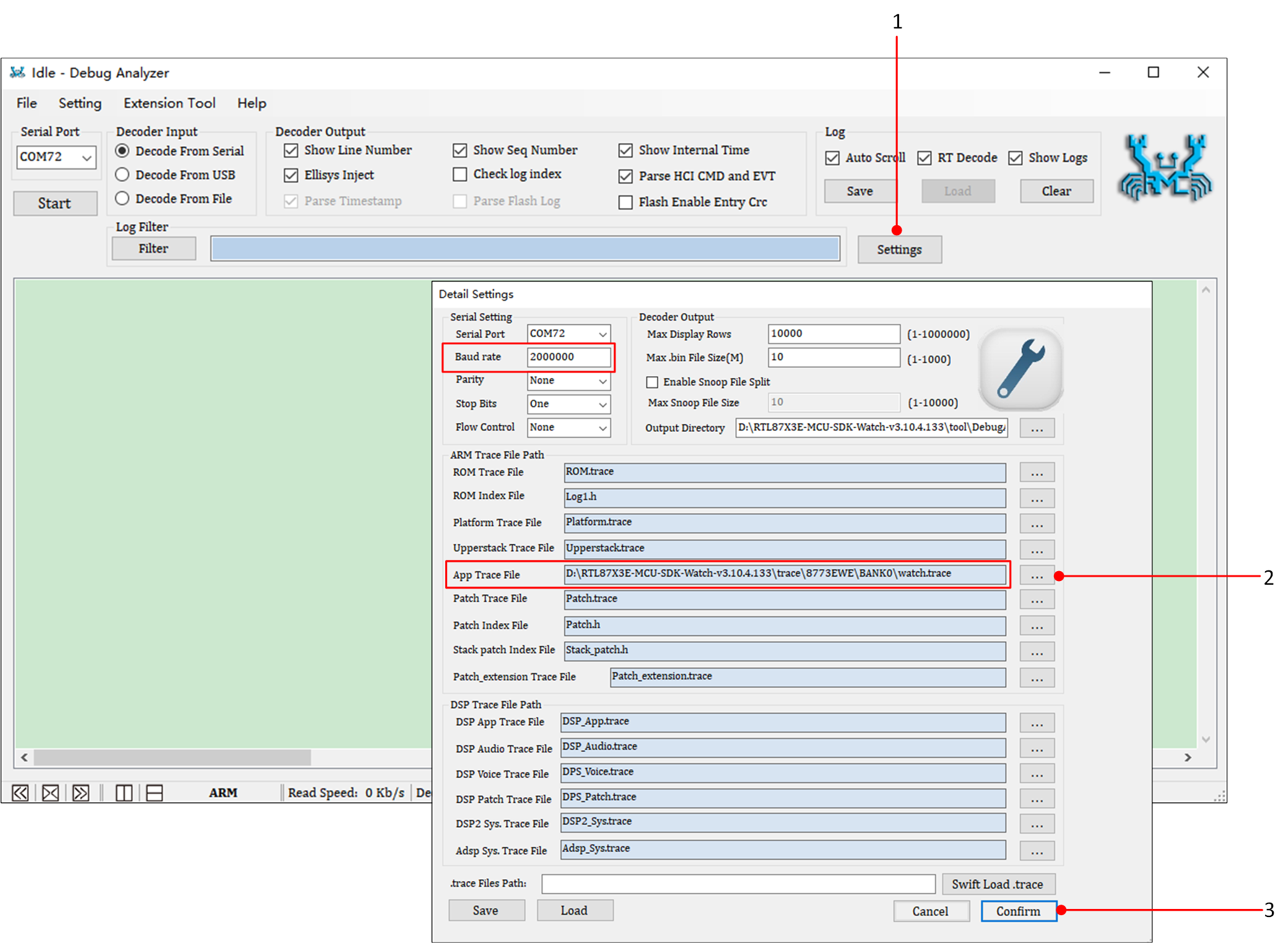
Debug Analyzer Parameter Setting Interface
Select the correct Serial Port, click Start, and Debug Analyzer will begin working. The main interface can be adjusted to display either ARM log or DSP log.
The PC will save the captured raw data (Raw Data) in a .bin file and, based on user settings in the .trace file, parse the raw data into plain text logs, saving them in a .log file.
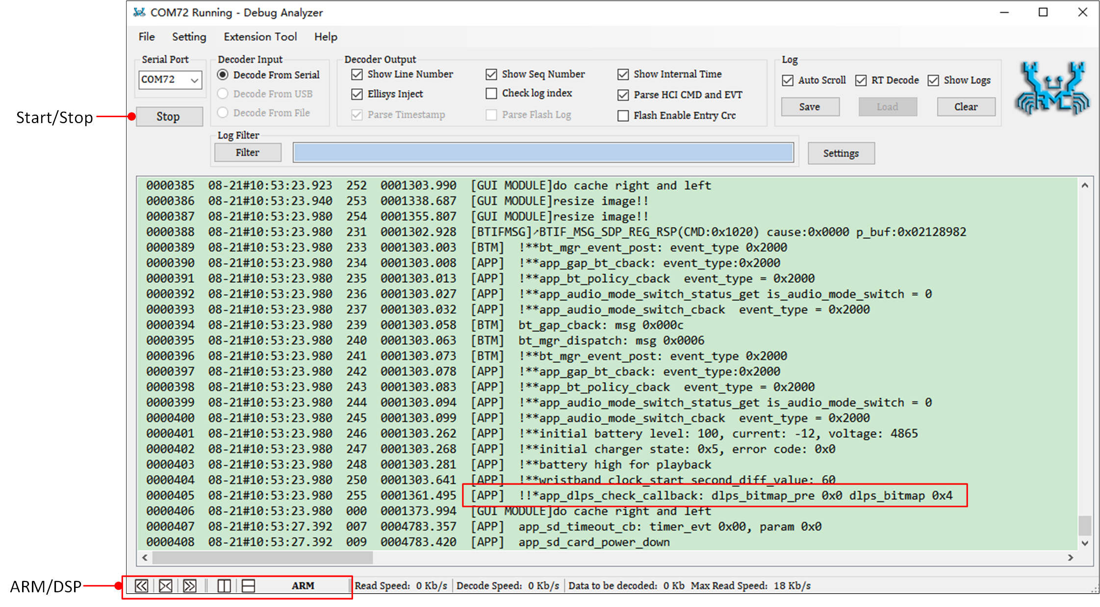
Capture Log
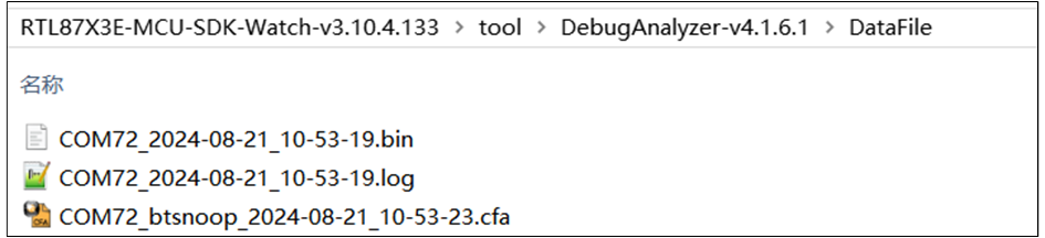
DataFile Folder
Note
Default log file save path: in the same directory as DebugAnalyzer.exe, in the DataFile Folder.
The
.tracefile is used to parse the binary log stream received via the serial port. A new.tracefile is generated each time the project is compiled. It is necessary to ensure that the.tracefile matches the currently running SoC code.During the development process, if encountering any issues, please provide the DataFile Folder path along with the
.log.bin.cfafiles and the.tracefile to facilitate Realtek's analysis and troubleshooting.