Design Spec
This document primarily introduces the development environment and software design architecture of the Realtek RTL8773E series watch SDK. It aims to enable users to quickly set up the environment on a hardware evaluation board and become familiar with the SDK by studying this document.
The RTL8773E series IC models mainly include RTL8773EWE, RTL8773EWE-VP, and RTL8773EWE-VS, supporting both NOR Flash and NAND Flash versions. Users should select the appropriate IC type according to their needs. The SDK provides basic functions commonly used in Bluetooth watches, including a GUI framework, Bluetooth link management, and music playback. The watch's Bluetooth connection supports both phones and headsets, achieving connection and data transfer through different protocols. The music scenarios include local music playback, playing music through connected headsets, and playing music from a phone, with audio data being processed and transmitted through different flows. The SDK also provides some example interfaces, allowing users to interact via the GUI interface.
Through this document, users can quickly familiarize themselves with the development environment and proceed with application development.
Practical Application Case
The diagram below shows the overall framework of the watch application.
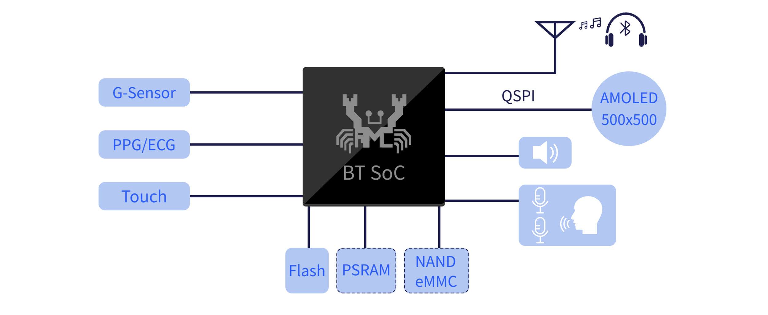
Application Case Of Watch
Requirements
RTL8773E evaluation motherboard
RTL8773E evaluation daughterboard
Display screen daughterboard
SD daughterboard
Microphone daughterboard
Speaker
3.7V battery or USB data cable for power supply
ARM Keil MDK
MPPG Tool
MCUConfig Tool
Debug Analyzer
Image Converter Tool
For more detailed usage, please refer to the Quick Start Guide.
Wiring
The evaluation board provides a hardware environment for user development and application debugging, composed of a motherboard and several daughterboards. It has download mode and work mode. Users need to use different connection methods to set the EVB to enter the required mode. For detailed introduction and usage of the EVB mainboard, please refer to the evaluation board guide.
Configurations
Some of the features included in the watch project can be enabled or disabled by the following macro definitions. Users can enable or disable functions based on their product requirements through switch macro definitions.
#define F_APP_SAVE_RECORD_FILE_TO_SD        1
#define F_APP_SAVE_RECORD_FILE_TO_FLASH     0
#define F_APP_PLAY_AND_RECORD               0

#define F_APP_A2DP_SOURCE_SUPPORT           1

#define F_APP_DSP_ONLINE_DEBUG_SUPPORT      0

#define F_APP_BLE_ANCS_CLIENT_SUPPORT       1

#define F_APP_HID_SUPPORT                   0
#define F_APP_HID_KEYBOARD_MOUSE_SUPPORT    0
#define F_APP_SUPPORT_NORMAL_OTA            1
#define F_APP_SC_KEY_DERIVE_SUPPORT         0
#define F_APP_NOT_ABS_VOL_SET_MAX_GAIN      0
#define F_APP_AIRSYNC_SERVICE_SUPPORT       0
#define F_APP_WECHAT_TRANSFER_SUPPORT       1

#ifdef TARGET_RTL8763E
#define F_APP_UI_ENGLISH_VERSION            0
#define F_APP_PACKAGE_QFN68                 0
#define F_APP_SUPPORT_USB                   1
#endif

#ifdef TARGET_RTL8773E
/*App feature setting*/
#define F_APP_HONEY_GUI                     1
#define F_APP_GUI_USE_PSRAM                 1
#define F_APP_GUI_RAMLESS                   0
#define F_APP_PACKAGE_QFN68                 1
#define F_APP_SUPPORT_USB                   0
#define F_APP_PPG                           0
#define F_APP_CWM                           0

/*Honeygui feature setting*/
#define RTK_MODULE_RTK_PPEV2
#define RTK_TP_ALGO_V2
#define RTK_ENABLE_RTK_SOC_WATCH            /*Enable for soc gui. Disable for simulator gui*/

/*Honeygui ui resource setting*/
#if (SUPPORT_NAND_FLASH == 0)
#define GUI_RESOURCE_NOR_FLASH
#else
#define GUI_RESOURCE_NAND_FLASH
#endif
#define GUI_RESOURCE_FILE_SYSTEM            0

#endif
Building and Downloading
Please refer to Quick Start for compilation and download. Since the SDK simultaneously supports both NOR Flash and NAND Flash versions, it is worth noting that:
Users need to distinguish between the images, flash maps, and trace files corresponding to the two types of flash types. The corresponding paths are as follows:
File Name |
File Path |
|---|---|
Image NOR version |
|
Image NAND version |
|
Flash map NOR version |
|
Flash map NAND version |
|
Trace NOR version |
|
Trace NAND version |
|
In the watch_ep project, there are two target options, among which watch_ep corresponds to NOR Flash by default, watch_ep_nand corresponds to NAND Flash.
-
When using the MPPG tool, pay attention to the selection of the IC type:
When burning the NOR version, select IC type RTL8773EWE or RTL8773EWE-VP.
When burning the NAND version, select IC type RTL8773EWE-VS.
Note
During development, in addition to the libraries shared by NOR and NAND, attention should also be paid to the distinction of paths: the NOR version is in
\bin\rtl87x3ep\nor_lib\, and the NAND version is in\bin\rtl87x3ep\nand_lib\.
Experimental Verification
UI Test Process
After correctly completing the firmware burning, switch the EVB to work mode and reset it.
The SDK has preset several UI interfaces. After the device restarts, see the 'Watch Face' interface. On the 'Watch Face' interface, swipe the window to view or modify the current mode. Swiping left on the 'Watch Face' interface switches to several other commonly used interfaces, including: Music Player, Call, Contacts, Recorder, Map, Standard Test, etc. Each page's controls, such as buttons, are interactive.
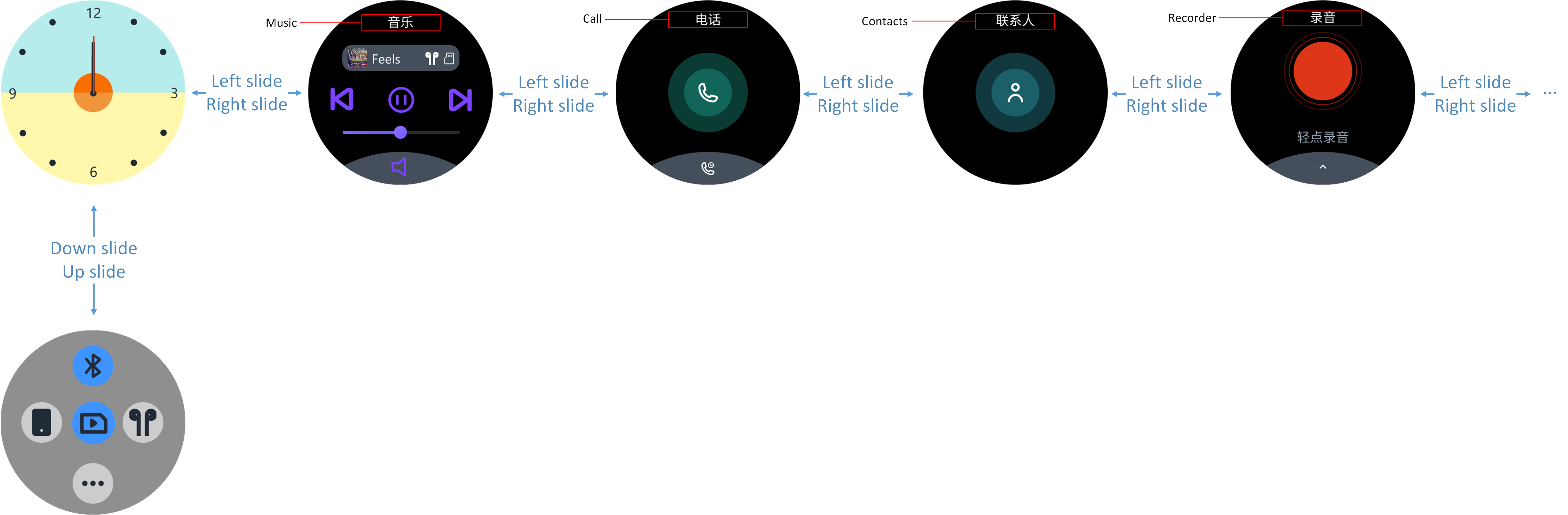
Watch UI Demonstration
Bluetooth Connection Test Process
This section focuses on the use of the UI. The logic for Bluetooth connection will be introduced in the Connection Modes section.
On the 'Watch Face' screen, open or close the Bluetooth by tapping the 'Bluetooth Icon' control.
With Bluetooth turned on, click the 'Phone Icon' or 'Headphone Icon' control to complete the respective Bluetooth connection. Once connected, the device information will be stored in the watch's bonding list.
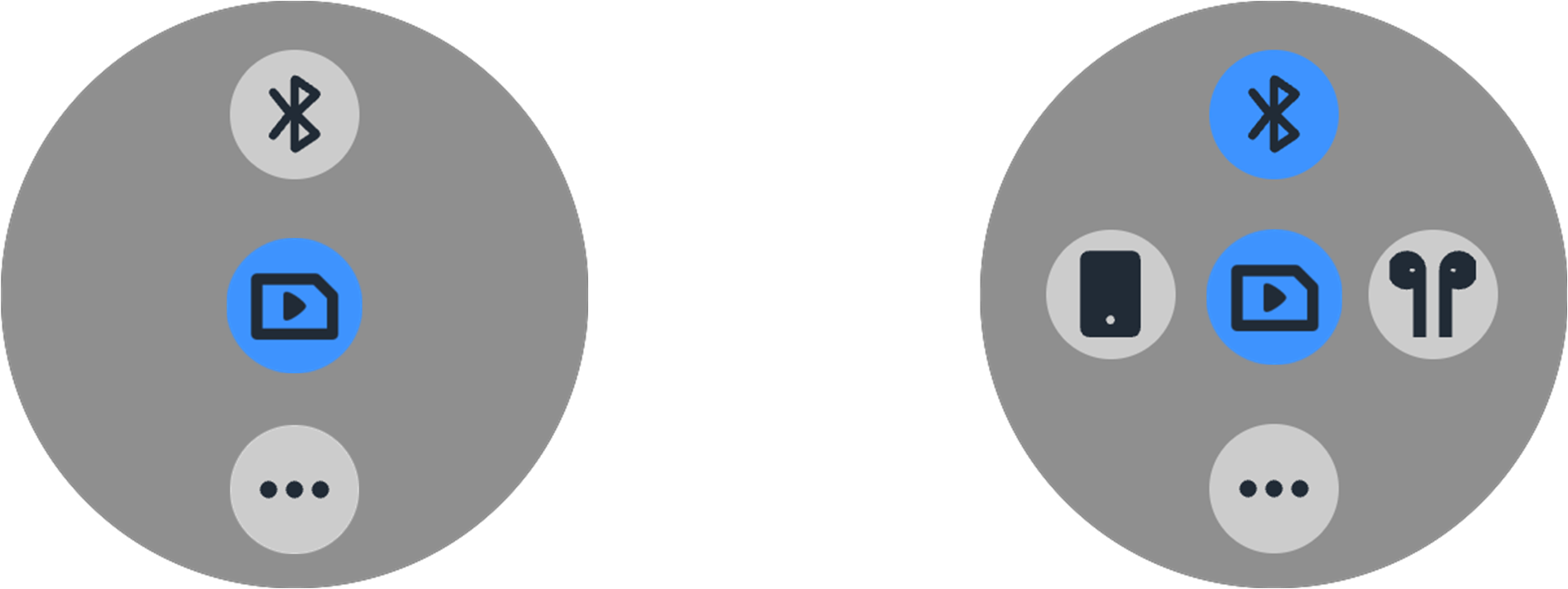
Bluetooth Switch UI
Connect to Phone
To connect a new phone for the first time, click on Connect to a new phone to view the current watch device's Bluetooth name and address. This way, the phone can search for the corresponding device and initiate the connection.
The connection process includes the connection of the ACL and Profile. Once connected successfully, the name of the connected phone will be highlighted in the 'Connect Phone' interface.
If this is not the first connection and the watch's bonding information has not been deleted on the phone, clicking the 'phone icon' will proactively reconnect to the phone.
On the 'Connect to a phone' screen, clicking on the phone name will also trigger the action to connect to the phone actively.
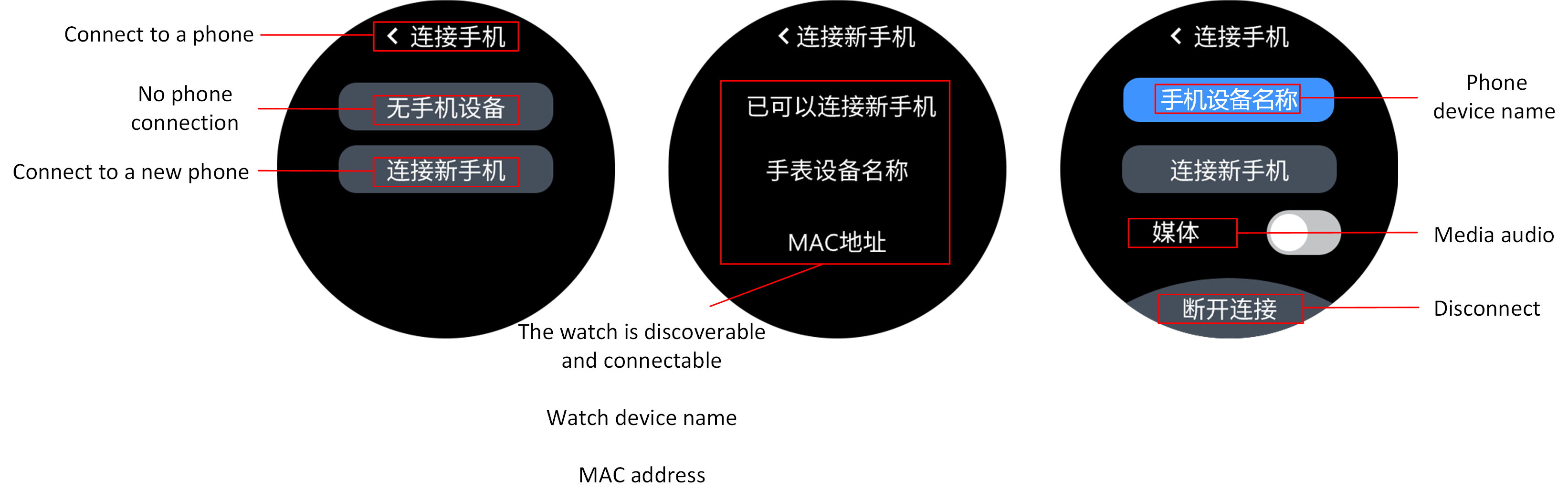
Connect To Mobile UI
Note
When connecting to the phone, profile connection will mainly focus on connecting HFP and PBAP, which will support the calling and contact synchronization functions.
After connecting to the phone, turn on the Media audio switch. The watch will actively initiate the A2DP protocol connection, which will support the function of playing phone music on the watch once successfully connected.
Connect Headphones
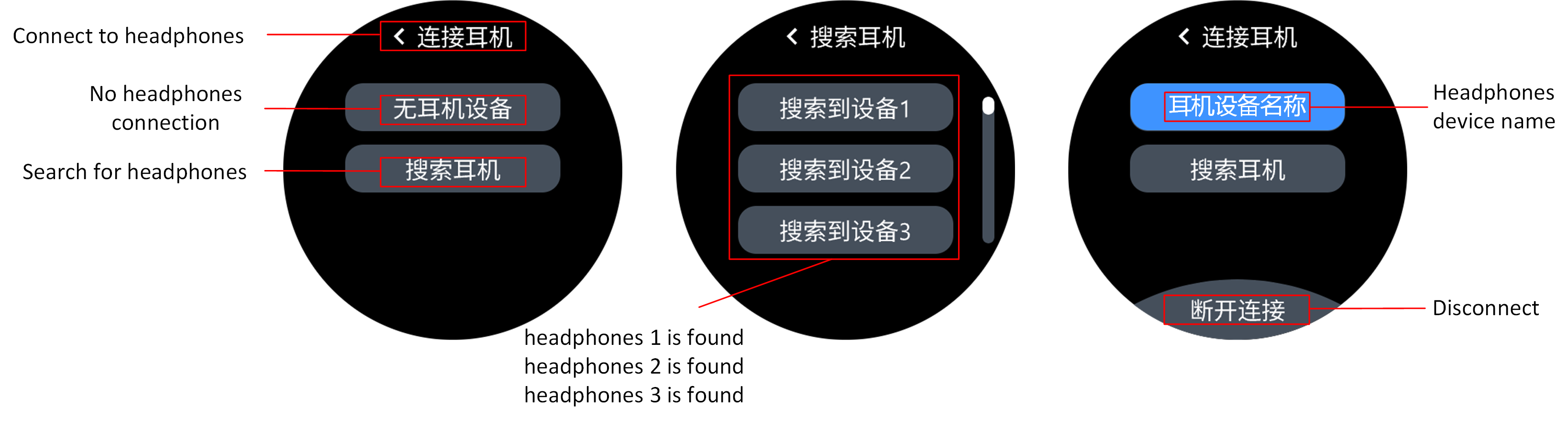
On the 'Connect to headphones' screen, actively scan for currently discoverable headphone devices by clicking on Search for headphones.
After finding the headphone device, the name of the headphones found will be displayed. Click again to initiate the connection, which includes the connection of ACL and Profiles ( A2DP and AVRCP ).
After a successful connection, the name of the connected headphones will be highlighted on the 'Connect to headphones' screen.
If the headphones are already on the bonding list, clicking the 'Headphones icon' will automatically reconnect to the most recently used headphones.
On the 'Connect Headphones' interface, actively clicking the headphone name will bring the user to the Headphone bonding List. Clicking the headphone name again will initiate the reconnection to those headphones.
Connecting Headphones UI
Music Playback Test Process
The watch currently supports three playback modes: local music playback, connection to headphones for music playback, and playback of phone music.
Local Music Playback
After powering on the watch, it defaults to local playback mode. If there is music in the SD/NAND, swipe to the music player UI interface and click the 'Play' button to hear the current music through the speaker.
In the 'Player' interface, click on the music title to enter the 'Playlist' interface. Click on a song title in the playlist to switch to playing that music.
During playback, switch the current music using the 'Previous' and 'Next' icons.
Swipe up from the bottom of the screen to open the volume control curtain and adjust the current volume by clicking the appropriate icons.
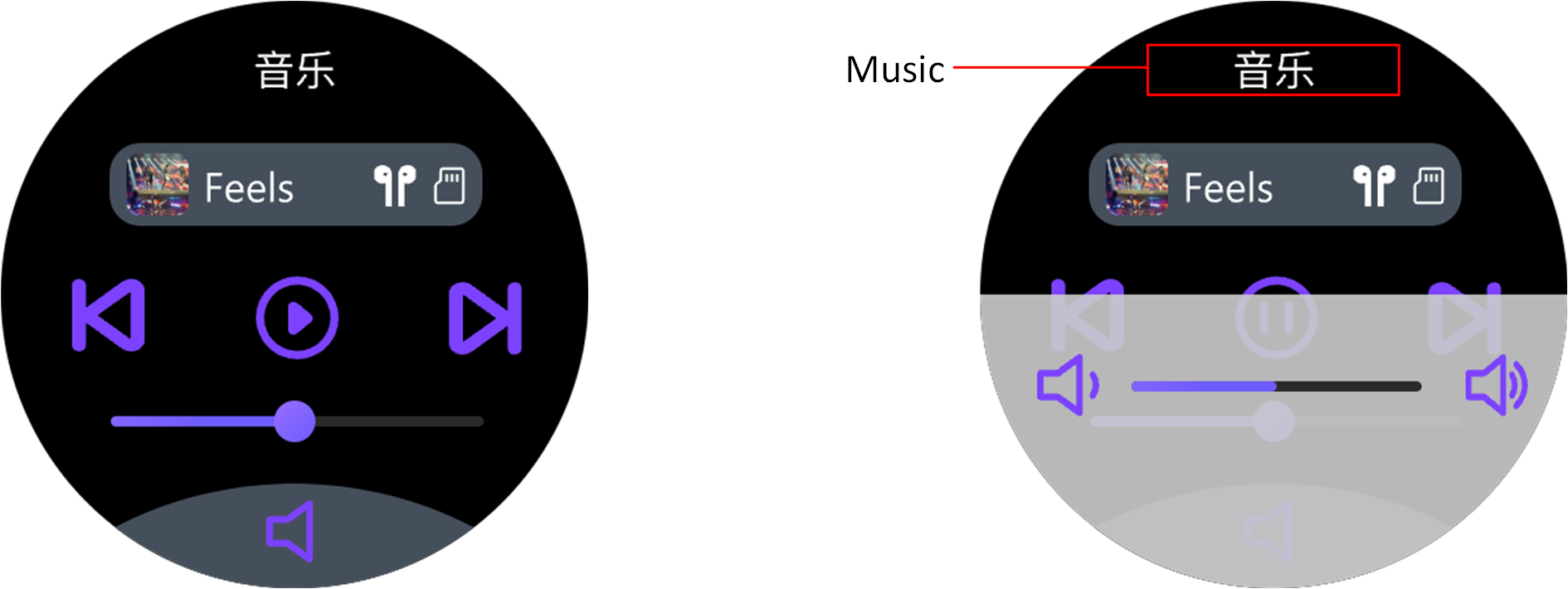
Player UI
Note
If there is no music in the SD/NAND, transfer music to the SD/NAND via the Audio Connect APP first.
Connect Headphones to Play Music
To connect headphones to play music, first complete connect headphones , after connecting the headphones, and in the case where there is music on the SD card, slide to the UI interface of the music player, click the 'Play' button, and listen to the currently playing music through the headphones. Headphones playback also supports the function of music switching and volume adjustment. The player's interface usage is the same as in local music playback.
Play Phone Music
To play phone music via the watch, first complete connect phone , after connecting the phone, turn on Media audio switch, then slide to the UI interface of the music player, click the 'Play' button, and listen to the currently playing music from the mobile player through the watch. Playing phone music does not support 'playlist', but the functions of song switching and volume adjustment are the same as in local music playback. Since the music source for mobile playback comes from the mobile, this function does not require an SD card.
Software Design Introduction
Software Architecture
The overall system architecture is as follows, composed of several important parts:
Application: User application code. The context will focus on the implementation of this part.
Framework: Responsible for audio pathways, classic Bluetooth Profiles, system management, etc.
LE Profiles/Services: Responsible for LE Service related definitions and providing data read/write interfaces.
GAP: Provides interfaces related to Bluetooth GAP.
IO driver: Offers various peripheral drivers, including GPIO, SPI, I2C, UART, QSPI, ADC, etc.
Platform: Provides platform-related interfaces, completes memory management, system boot mechanisms, power management, OS management, etc.
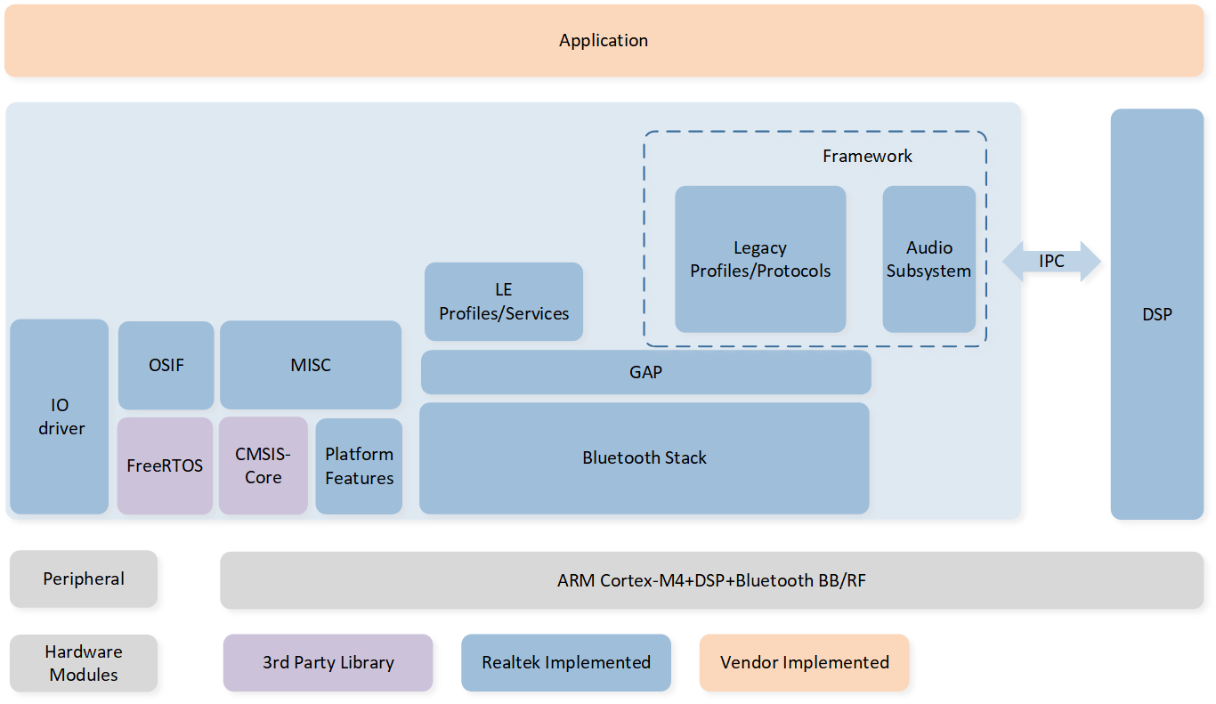
System Architecture Diagram
Note
Detailed information can be referenced from Platform.
Please note that due to differences in software development versions, the SDK information described in this document may not be fully consistent with that in the linked documentation. Please review both sources and adopt the information according to your actual requirements.
Directory Structure
The directory interface of the watch project is illustrated in the following diagram.
└── Project: watch_ep/watch_ep_NAND
    ├── include                        Compile configuration
    ├── cmsis                          Boot and other system settings
    └── lib
        ├── gap_utils.lib
        ├── framework.lib
        ├── ROM.lib
        ├── filesystem.lib             library files
        ├── upperstack_4M.lib
        ├── hal_utils.lib
        ├── RTL87x5PPG.lib
        ├── CWM_LIB_DML_Keil_m3.lib
        └── CWM_LIB_Keil_m3.lib
    ├── ble_Profile                    BLE profiles
    ├── module                         Peripheral module, including key, touch screen, sensor, and so on.
    └── watch_app
        ├── main.c
        ├── app_task.c
        ├── app_cfg.c                  Watch app
        :
    ├── lcd_driver                     LCD driver
    ├── hub_task                       Peripheral management
    ├── communicate                    Example of BLE interaction profile
    ├── Localplayback                  Local playback, music transmission-related code
    ├── dfu
    ├── dfu_task                       DFU, OTA demo code
    ├── console                        UART console demo code
    ├── mp                             MP test code
    ├── honey_gui                      HoneyGUI
    ├── peripheral                     Display Controller
    └── gui_application
        ├── app_gui_main.c
        ├── watchface_mgr.c            GUI demo
        ├── player_mgr.c
        ├── call_mgr.c
        :
    ├── ppe                            PPE
    ├── PPG                            PPG
    └── cwm                            CWM algorithm
Task and Priority
RTL87x3E uses the FreeRTOS, which includes built-in timer tasks, upper stack tasks, lower stack tasks, and idle tasks.
Using the HoneyGUI architecture will create a GUI task. Additionally, the Watch application also independently creates app tasks, hub tasks, and communication tasks.
Task descriptions and priorities are as follows:
Task |
Description |
Priority |
|---|---|---|
Timer |
Implement software timers required by FreeRTOS |
6 |
BT Controller stack |
Implement BT and BLE protocol stack below HCI |
6 |
BT Host stack |
Implement BT and BLE protocol stack above HCI |
3 |
Register callback functions to handle BT and BLE related states and freely implement controls for Bluetooth and audio |
2 |
|
HUB |
Separate lower-level drivers from the upper layers and handle upper-level messages from peripherals |
1 |
Communicate |
Example of BLE data transmission management |
1 |
GUI |
Handle UI display and interaction |
1 |
Idle |
Run background tasks |
0 |
GUI Description
GUI Interface
Currently, the SDK provides several example GUI interfaces including: watch face interface, player interface, call interface, contacts interface, recording interface, map interface, benchmark test, and configurable visible heart rate band interface.
Currently, TabView is used to manage and navigate between interfaces by attaching tabs underneath. Taking the player interface as an example: two tabs, 'Main Playback Interface' and 'Playlist', are attached under the TabView. In the Main Playback Interface tab, a 'Volume Control' curtain is created.
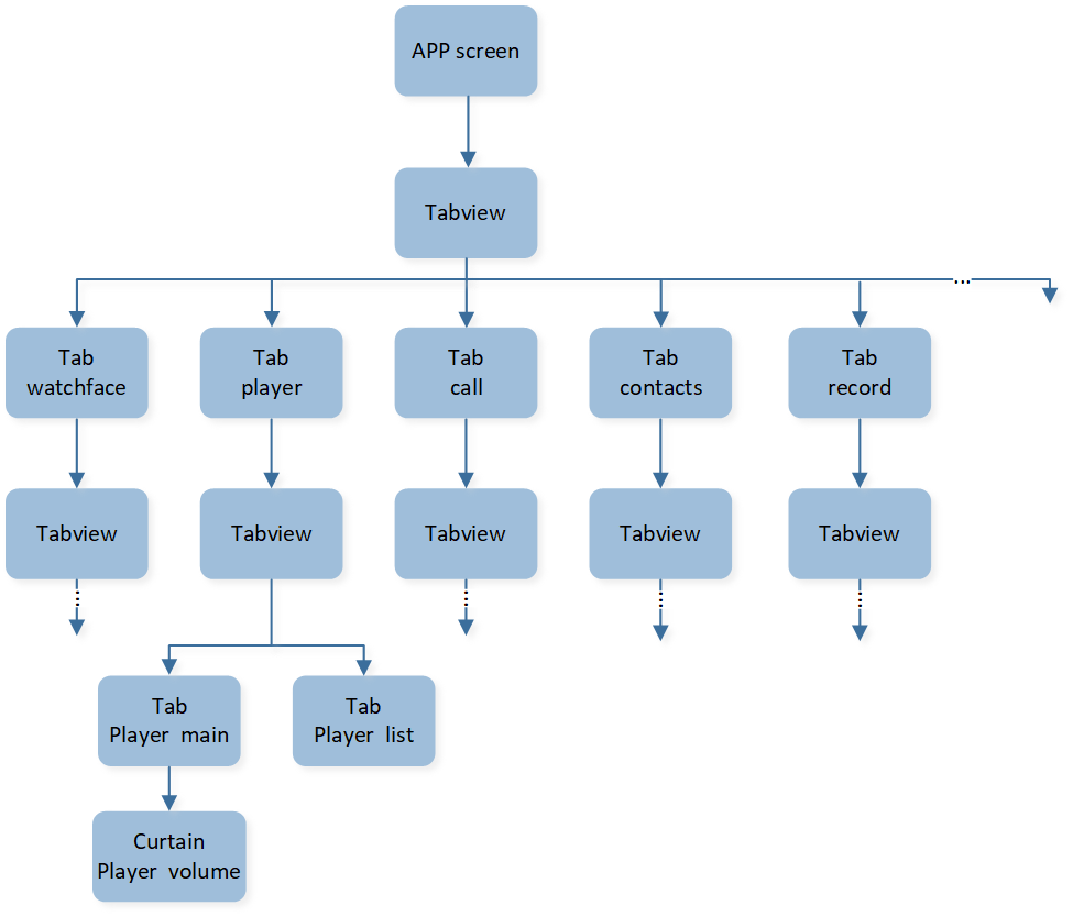
Watch Interface Logic Diagram
GUI Update Event
GUI update events are typically used for communication from other tasks to the GUI task. This functionality is achieved through events and callbacks bound to GUI controls, as well as the message receiving mechanism of the GUI server. Since the processing of update events takes place at the final stage of the GUI server task's execution, it enables safer dynamic creation and destruction of GUI controls.
A GUI update event that can be responded to usually involves the following steps:
.
Update Event Enumeration
In the watch SDK, gui_event_user_t is used to represent the enumeration set of update events. It is important to note that the enumeration values for update events must be greater than GUI_EVENT_USER_DEFINE; only then can the watch SDK correctly recognize and respond to them as GUI update events.
Update Events and Add Callback
User can use interface gui_obj_add_event_cb() to add GUI update events and callbacks to specified GUI controls.
This function is also used for adding other GUI events and callbacks, usually encapsulated in the interface of GUI controls.
Update Event Push
Interface gui_update_by_event(gui_event_user_t event, void *data, bool force_update) is used for pushing GUI update events.
The event and data parameters are used to fill the sub-event and payload of
gui_msg_t.The force_update parameter determines whether another message from structure
GUI_EVENT_DISPLAY_ONwill be pushed to perform LCD wake-up.
After gui_update_by_event() is executed, a GUI message will be sent to the GUI task through the gui_send_msg_to_server() interface.
Update Event Response
In the final stage of GUI server operation, gui_recv_msg_to_server() will be executed to process the messages received by GUI tasks.
When receiving event = GUI_EVENT_USER_DEFINE, the GUI will pass the msg back to the callback for the user to handle the GUI msg themselves. The SDK will process the received GUI update event at this stage.
Match based on sub_event, payload, and events added by
gui_obj_add_event_cb(). If the match is successful, execute the added callback.
Code Example
In this example, a tab page adds events for CALL_INCOMMING and CALL_OUTGOING and their corresponding callbacks. After notifying the GUI task in function app_hfp_bt_cback(),
the GUI will jump to the corresponding page.
static void gui_call_status_update_cb(void *obj, uint16_t event, void *param)
{
   gui_log("gui_call_status_update_cb\n", event);
   switch (event)
   {
   case GUI_EVENT_CALL_INCOMING:
      {
            app_call_switch_tabs(CALL_INCOMMING);
      }
      break;
   case GUI_EVENT_CALL_OUTGOING:
      {
            app_call_switch_tabs(CALL_OUTGOING);
      }
      break;
   default:
      break;
   }
}
...
void design_tab_call_main(void *parent)
{
   ...
      // add event to update incomming/outgoing/active/end call gui
      gui_obj_add_event_cb(parent, (gui_event_cb_t)gui_call_status_update_cb,
                           (gui_event_t)GUI_EVENT_CALL_INCOMING,
                           NULL);
      gui_obj_add_event_cb(parent, (gui_event_cb_t)gui_call_status_update_cb,
                           (gui_event_t)GUI_EVENT_CALL_OUTGOING,
                           NULL);
   ...
}
...
static void app_hfp_bt_cback(T_BT_EVENT event_type, void *event_buf, uint16_t buf_len)
{
   ...
   Case BT_EVENT_HFP_CALLER_ID_IND:
   gui_update_by_event(GUI_EVENT_CALL_INCOMING, NULL, true);
   ...
}
Note
For additional detailed introduction to HoneyGUI, please refer to the GUI Documentation.
Please note that due to differences in software development versions, the SDK information described in this document may not be fully consistent with that in the linked documentation. Please review both sources and adopt the information according to your actual requirements.
Audio Scene
Music Playback Management
header.bin and name.bin
For the local music playback and headphone connection music playback features, MP3 files are stored in SD/NAND. To facilitate song information indexing, the SDK uses two files, header.bin and name.bin, to manage the songs. The following is an introduction to the storage format of header.bin and name.bin.
The name.bin file stores the names of various songs, formatted as follows:
Song name1 |
Song name2 |
Song name3 |
... |
|---|---|---|---|
Name data1(Unicode) |
Name data2(Unicode) |
Name data3(Unicode) |
... |
header.bin is used to describe the total number of songs and the offset, length, and other information of each song name in name.bin.
Count |
Reserved |
HEAD INFO1 |
HEAD INFO2 |
... |
|---|---|---|---|---|
2 bytes |
4 bytes |
sizeof(T_HEAD_INFO) |
sizeof(T_HEAD_INFO) |
... |
For the HEAD INFO of each file, follow the definition below.
typedef struct
{
   uint32_t offset;         // Start offset of the song name
   uint16_t length;         // Length of the song name
   uint16_t plIndex;        /* Play List Index, indicates which playlist the song belongs to.
                              0x0: belongs to no playlist, 0x1: belongs to playlist1. */
   uint8_t isDeleted : 1;   /* Flag indicating if the song is deleted.
                              1: deleted,
                              0: not deleted. */
   uint8_t needToUnlink : 1; /* Flag indicating if the song needs to be unlinked.
                              1: needs to call audio_fs_unlink to delete the file,
                              0: does not need to unlink. */
   uint8_t extension : 6;
   uint8_t fil_ext;         /* File extension */
   uint8_t rsv;             /* Reserved for future usage, should be set to "0" */
} __attribute__((packed)) T_HEAD_INFO;
Because the offset and length of each song are provided in the HEAD INFO, the names of the songs can be extracted using name.bin.
Note
For the convenience of application layer song display and list management, these two bin file information can be read and saved to flash/PSRAM. When needed to play a specified song, the corresponding song name can be passed to the file system interface to complete the playback of the song directly.
Music Playback Control
Audio control includes play, pause, skip songs, volume adjustment, etc.
Regular playback, pause, skipping songs, and volume adjustment can be accomplished through MMI commands. In different playback modes, the upper layer shares MMI commands, and further distinctions are made in the lower functional code.
For playing specified songs, use the app_audio_play_by_name() interface, passing the song name information to realize the corresponding song playback.
Note
The behavior defined by the MMI commands can be referred to in
T_MMI_ACTION, while the implemented function can be referred to inapp_mmi_handle_action().
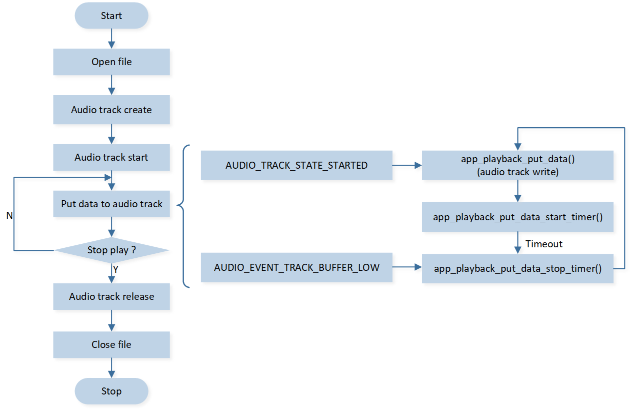
Local Music Playback Flow
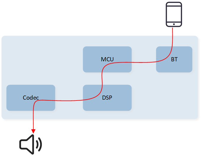
In the local music playback scenario, MCU reads the local audio file, parses the relevant data packets, sends them to DSP for processing, and outputs to the codec for playback at the local speaker.
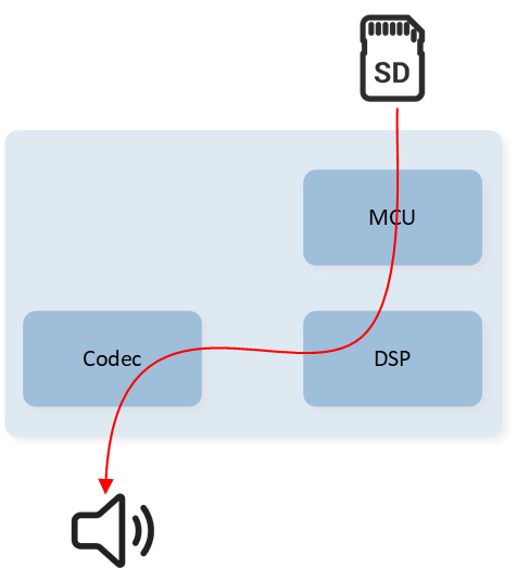
Audio Data Stream Of Local Music Playback
Main Processing Flow:
The entry function for local music playback is
app_audio_play_by_name(). After passing the music file name and calling it, the music playback process begins.Open this file and obtain the MP3 handle. All subsequent operations on the MP3 file will be based on this handle.
Create, configure, and start the audio track based on the parameters of the MP3 file (e.g., sampling rate, bitrate).
-
Next, write the MP3 data frames into the audio track to play the local audio. There are mainly two instances to drive the writing of data frames:
Once the audio track starts, data will begin to be written to the audio track, and a timer will be initiated to periodically read and write MP3 data frames.
When the audio track check detects a low water level, the app will also write data to the audio track to prevent playback stuttering and other issues.
Release the audio track and MP3 handle, and close the file either after the user's audio playback is complete or the user manually stops the playback.
Local Music Playback Process
Connecting Headphones to Play Music Flow
The difference when connecting headphones to play music as opposed to local playback is that after DSP processes the MP3, it does not play directly but encodes again, and the encoded MCU data is sent back to the upper layer. After the MCU receives the data, it sends it to the headphone end through the A2DP protocol, where the headphones decode and play it.
As connecting headphones to play music involves using A2DP, the watch acts as a source, so this scenario is also referred to as A2DP source playback.
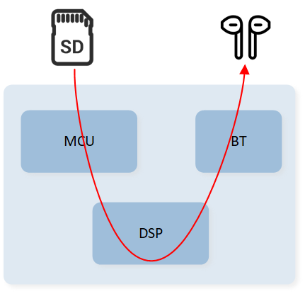
Audio Data Stream Of Connecting Headphones To Play Music
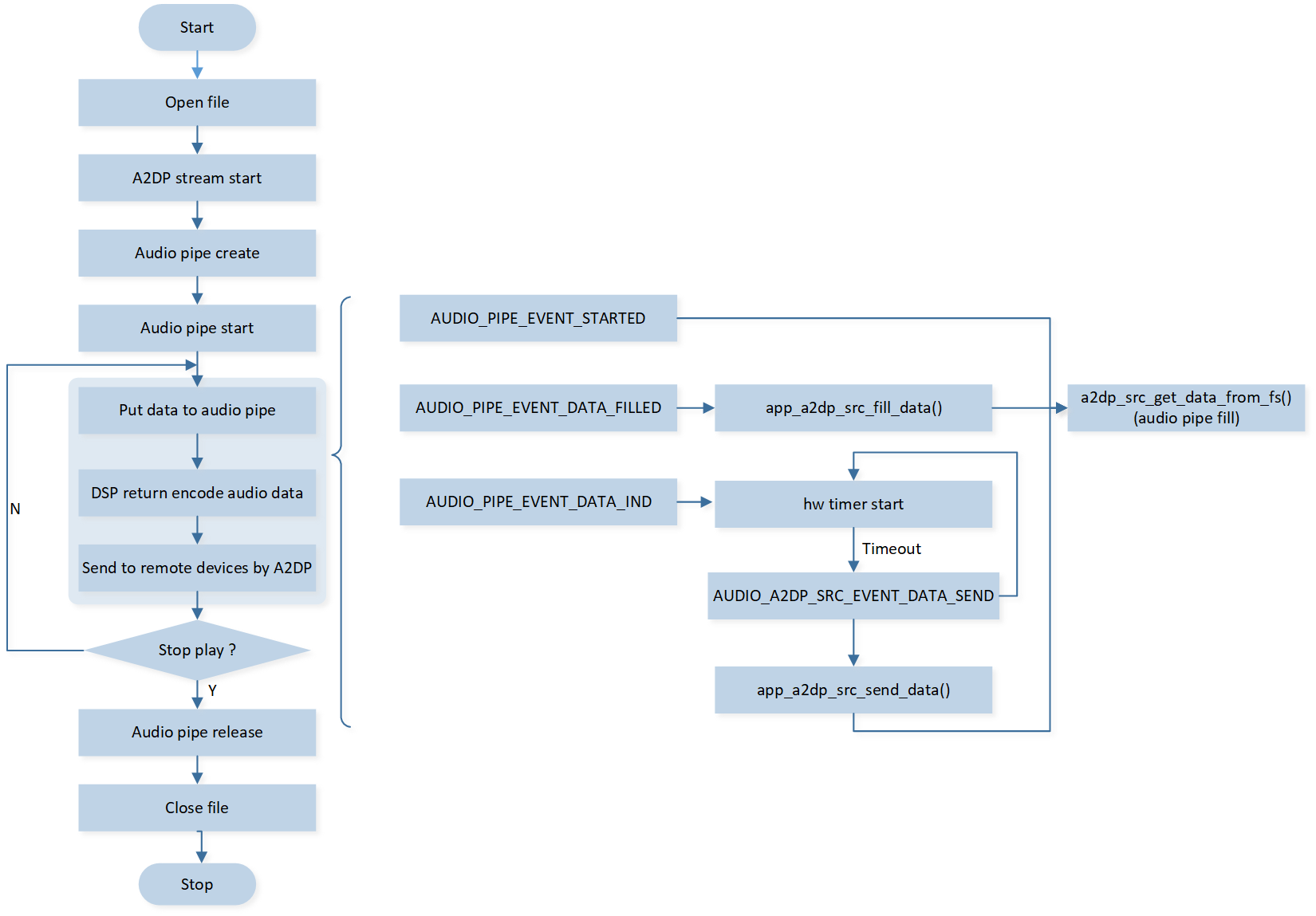
Main processing steps:
Similar to local music playback, the entry function for A2DP source playback is also
app_audio_play_by_name(). After calling this function with the music file name, the music playback process begins.Open the file to get the MP3 handle, from which all operations on the MP3 file will be conducted.
If the A2DP stream is not yet open, open the A2DP stream. Once the A2DP stream is successfully opened, the
BT_EVENT_A2DP_STREAM_START_RSPevent will be returned.Based on the parameters of the MP3 file (sampling rate, bit rate, etc.), create, configure, and start the audio pipe.
-
Afterwards, fill the audio pipe with MP3 data, while converting the audio pipe into SBC data and sending it to the headphones through the A2DP protocol. The specific steps are:
After the audio pipe is activated, the first packet of data is driven by the APP to fill the audio pipe with data.
Initially, the level is low, and after receiving the
AUDIO_PIPE_EVENT_DATA_FILLEDevent, it needs to fill the audio pipe with data to change the status to high.After the audio pipe successfully converts and outputs the SBC data, it will report through
AUDIO_PIPE_EVENT_DATA_IND, and the APP will store the SBC data in the buffer queue, activate the hardware timer, and send it once the sending cycle arrives.Once the process starts, the hardware timer will drive the APP to retrieve and send data through the report
AUDIO_A2DP_SRC_EVENT_DATA_SEND.
Until the user finishes playing the audio or stops actively, release the audio pipe and MP3 handle, and close the file.
Connecting Headphones To Play Music Process
Playback Phone Music Flow
The mobile phone music scenario involves the mobile sending audio data through A2DP. The smartwatch receives the audio data, decodes it on DSP, and outputs it to the codec for local speaker playback.
Due to the music playback scenario on smartphones, the smartwatch uses A2DP with the role of sink, so this scenario is also referred to as A2DP sink playback.
Audio Data Stream Of Playback Phone Music
Main processing flow:
Request to open A2DP stream and simultaneously create an audio track for sending data to DSP.
After the audio track is activated, the smartphone sends A2DP stream data which is reported via
BT_EVENT_A2DP_STREAM_DATA_IND, the MCU writes the audio data into the audio track and sends it to the DSP for decoding and playback.When the smartphone sends a Stop or Close command, the MCU stops sending audio data to the DSP and releases the corresponding audio track.
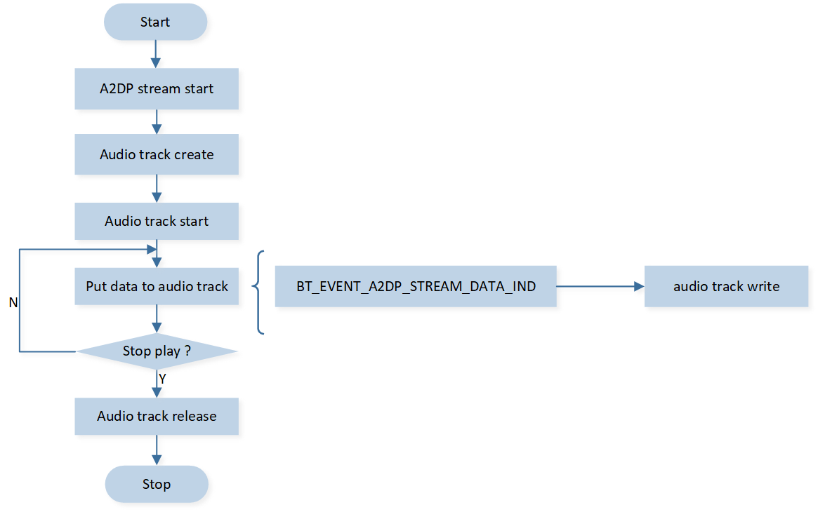
Playback Phone Music Process
Phone Audio Processing Flow
The phone scenario utilizes the HFP feature, with call audio transmitted via the SCO link. The watch's MCU needs to coordinate with the DSP to handle both uplink and downlink data simultaneously.
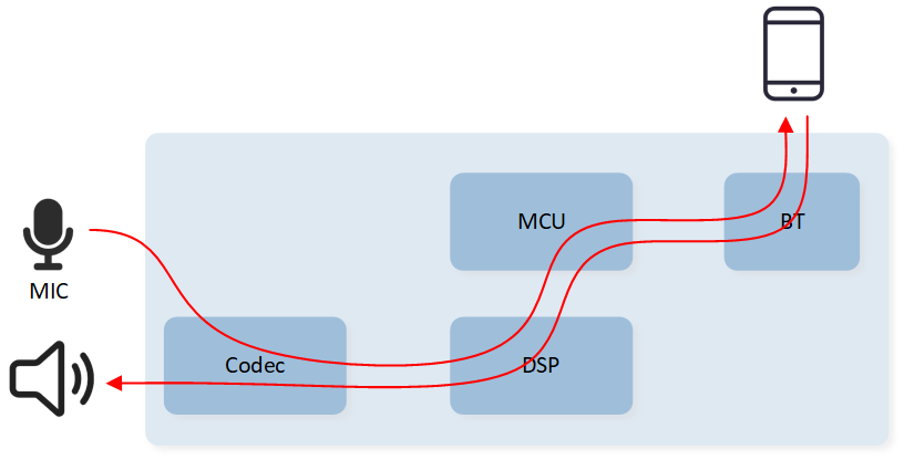
Audio Data Stream Of Phone
Main Processing Flow:
First, request the creation of an SCO link.
After the SCO link is established, create an audio track for reading and writing audio data.
After the audio track is started, the mobile phone sends audio data, which the MCU transfers to the DSP for decoding and playback through the audio track. Simultaneously, the audio track reads MIC data and sends it to the mobile phone.
Release the corresponding audio track until the SCO link is disconnected.
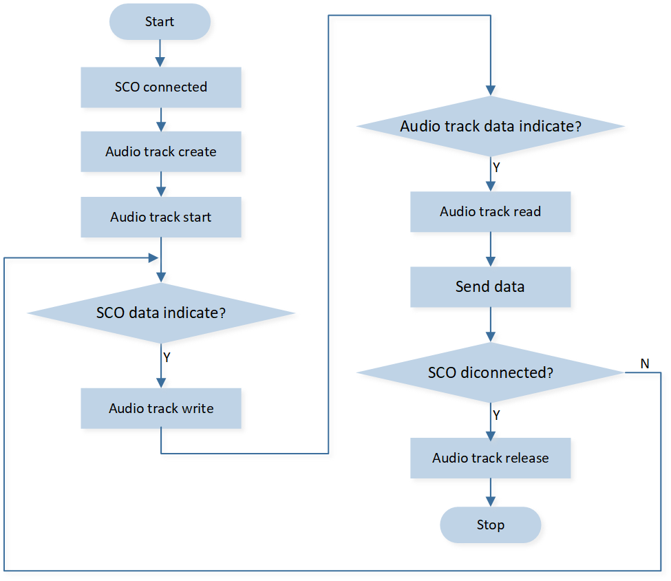
Call Handling Process
Note
For detailed explanations of audio concepts such as Audio track and Audio pipe, please refer to Audio Subsystem
Please note that due to differences in software development versions, the SDK information described in this document may not be fully consistent with that in the linked documentation. Please review both sources and adopt the information according to your actual requirements.
Bluetooth Connection
The Bluetooth connection of the watch is primarily for connecting to phones and headphones. It also supports connection to a computer when DSP online debugging is required. The protocols and processing procedures on the watch side differ slightly depending on the device.
typedef enum {
   DEVICE_TYPE_PHONE           = 0x00,
   DEVICE_TYPE_EARPHONE        = 0x01,
   DEVICE_TYPE_PC              = 0x02, // for DSP online debugging
   DEVICE_TYPE_DEFAULT         = 0x03,
} DEVICE_TYPE;
Classic Bluetooth protocols commonly used in watch applications include A2DP, AVRCP, HFP, PBAP, and SPP. When initializing each protocol, the corresponding callback interfaces will be registered. This way, when related protocol events occur, they will notify the upper layer through the respective callback interfaces.
bt_mgr_cback_register(app_hfp_bt_callback);
bt_mgr_cback_register(app_pbap_bt_callback);
bt_mgr_cback_register(app_avrcp_bt_callback);
      ...
Note
For detailed information on each protocol, please refer to BREDR Profiles.
Please note that due to differences in software development versions, the SDK information described in this document may not be fully consistent with that in the linked documentation. Please review both sources and adopt the information according to your actual requirements.
Bonding List Management
The watch supports bonding up to 8 devices, including 1 phone and 7 headphones. Use the connection information table T_APP_BOND_DEVICE to manage the connected devices, with the first slot reserved for the phone.
Definition of device connection information includes: device address, device connection status, device type, device name, device priority, whether the device currently exists, device name length.
Manually add/delete/modify/query the table according to the connection status, primarily implemented in app_bond.c.
To prevent power-off data loss, the table content will be synchronously saved in FTL, and each time the device is powered on, data will be fetched from FTL to the global variable.
typedef struct
{
    uint8_t bd_addr[6];
    bool used;
    T_DEVICE_TYPE device_type;
    uint16_t device_name[MAX_DEVICE_NAME_NUM];
    uint16_t priority;
    uint8_t exist_addr_flag;
    uint8_t device_name_len;
} T_APP_BOND_DEVICE;

typedef struct
{
    ...
    T_APP_BOND_DEVICE           bond_device[MAX_BOND_INFO_NUM];
    ...
}
T_APP_DB;
Connection Status Introduction
Bluetooth needs to enable Inquiry scan mode to be searchable by other Bluetooth devices and enable Page scan mode to be able to respond to connection requests from other Bluetooth devices. The lower layer combines Page and Inquiry to define the following four modes:
typedef enum t_bt_device_mode
{
    BT_DEVICE_MODE_IDLE                     = 0x00, /**< Page scan and inquiry scan disabled */
    BT_DEVICE_MODE_DISCOVERABLE             = 0x01, /**< Inquiry scan enabled */
    BT_DEVICE_MODE_CONNECTABLE              = 0x02, /**< Page scan enabled */
    BT_DEVICE_MODE_DISCOVERABLE_CONNECTABLE = 0x03, /**< Page scan and inquiry scan enabled */
} T_BT_DEVICE_MODE;
Settings for the mode combining APP, packaged into several Bluetooth states, can be set through app_bt_policy_enter_state(). The transformation relationship is as shown in the figure:
In the Bluetooth off state, the state is STATE_INIT, corresponding to BT_DEVICE_MODE_IDLE, and other Bluetooth devices are not allowed to discover and connect.
By turning on the Bluetooth switch, change to STATE_STANDBY, corresponding to BT_DEVICE_MODE_DISCOVERABLE_CONNECTABLE, allowing other Bluetooth devices to discover and connect.
For devices with bound information in the connection information table, the wristwatch can actively initiate a connection, entering the STATE_LINKBACK state. At this time, the current settings for Inquiry scan and Page scan will not change.
When the reconnection ends or if the connection is successful or fails under other circumstances,
app_bt_policy_set_state()will change to the corresponding state according to the current connection status of the phone/headphones: STATE_STANDBY, STATE_CONNECTED_PHONE, STATE_CONNECTED_EARPHONE, STATE_CONNECTED_TWO. The state will be updated to the corresponding Inquiry scan and Page scan mode, which can be modified by the user as needed.
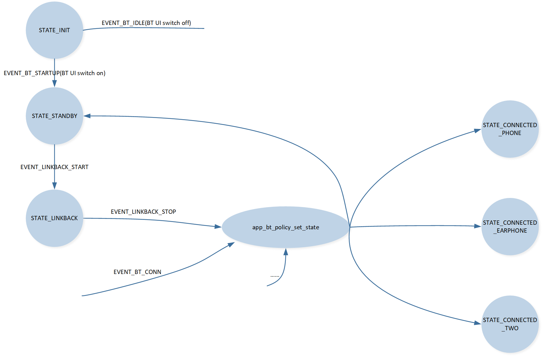
Bluetooth State Switching Diagram
Connection Modes Introduction
Connecting to Phone
To connect to the phone for the first time, ensure that the Bluetooth switch is turned on, i.e., the Bluetooth is not in the STATE_INIT state. On the phone end, search and discover the wristwatch device, and actively initiate a connection.
After a successful connection, the information of the connected phone will be stored in the device's connection information table by default. If the phone has not deleted the wristwatch information, the wristwatch can actively initiate reconnection to the phone if disconnected.
Connection to Headphones
There are three methods to connect headphones to the smartwatch:
Active scanning connection: This method must be used when connecting a new earphone device for the first time. During the scanning connection, if there are headphones already connected, it will disconnect the current connection and connect to the actively scanned device.
Direct connection from the paired list: This is suitable when there are headphones in the paired list. If there are already connected headphones, it will disconnect the current headphones and connect to the selected device.
Headphones reconnect to the smartwatch: This can only be successful when the smartwatch is not connected to any headphones or speaker devices.
Link Back Logic
The link back of the smartwatch relies on the device connection information list. The main link back scenarios under bonding information conditions are as follows:
Active link back to the device from the bonding list in the UI.
-
Link back during the music mode switching process:
When switching to local playback, if there is a mobile phone in the device connection information list, it will link back to the mobile phone. At this time, the main connection protocols are HFP, PBAP, supporting functions like making calls and synchronizing contact lists.
When switching to A2DP Sink playback, it is first necessary to determine whether the current A2DP role is Sink. If not, it needs to be switched to the Sink role. If there is a phone in the device connection information table, it will link back to the phone. The protocols connected at this time are HFP, PBAP, A2DP, and AVRCP. In addition to supporting call functions and phonebook synchronization, it also supports phone music playback.
When switching to the function of playing music through connected headphones, it is also necessary to first determine the A2DP role. If it is not the Source, it needs to be switched to the Source role first. Then, based on whether there is a phone connection when switching modes, decide whether to link back to the phone. Finally, if there is a headphones device in the connection information table, it will actively reconnect to the highest priority (most recently connected) headphones device.
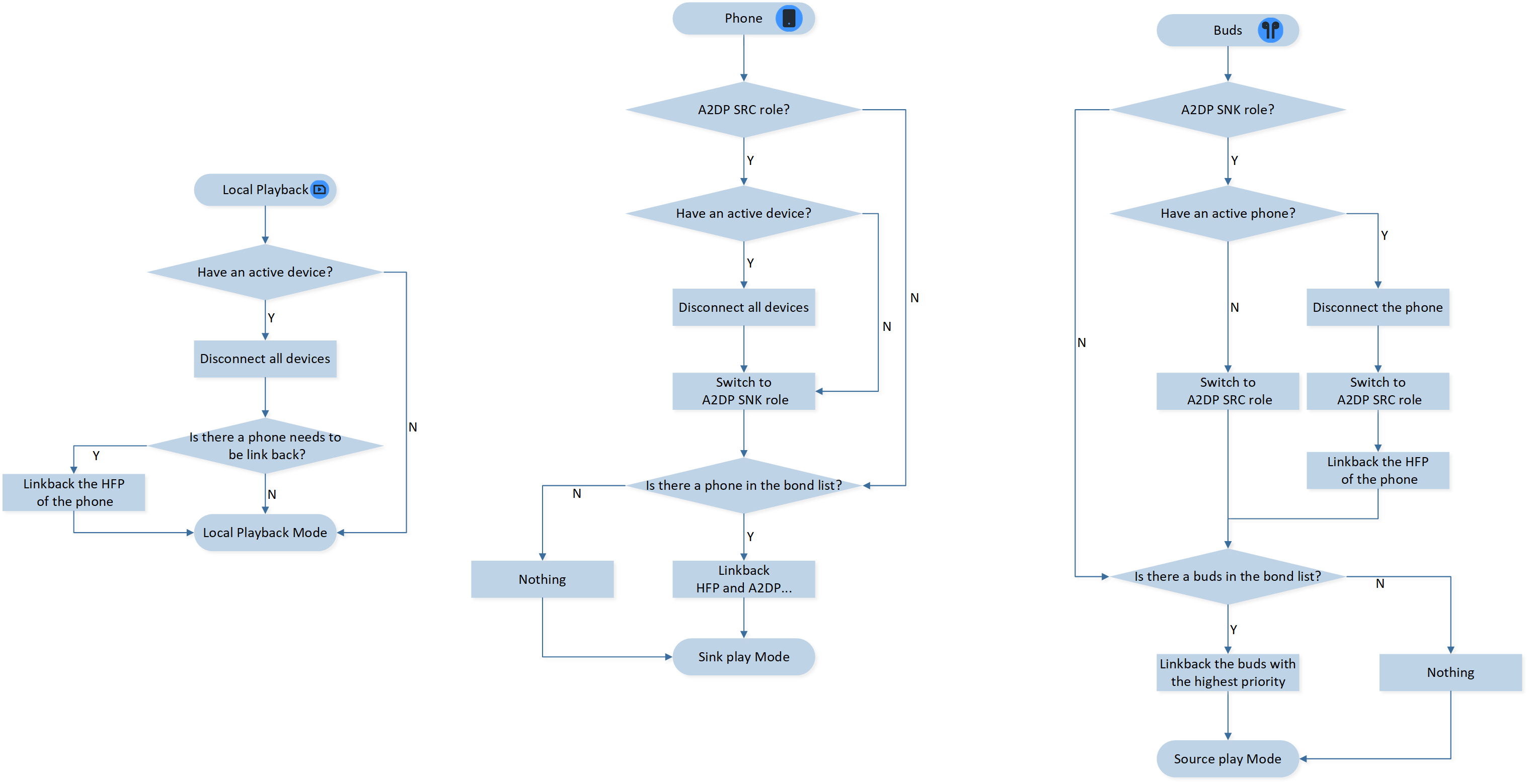
Music Mode Switch Diagram
Note
If the UI is in phone music or headphone music mode without the corresponding device connected, music will not play properly.
Upon successfully connecting the ACL link, proactively initiate the profile connection based on the function. In cases of disconnection or connection failure, set whether to initiate an ACL linkback or a Profile linkback based on the reason.
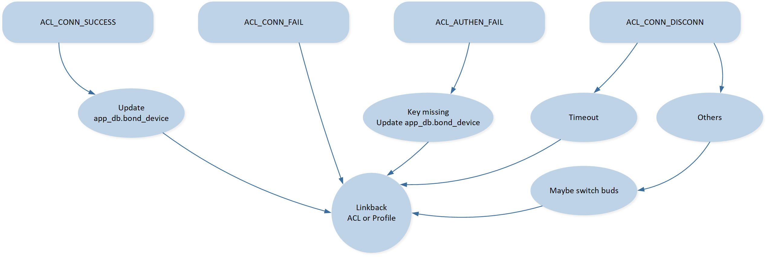
Reconnect In Bluetooth Interaction
Note
In the linkback process, only one device can be reconnected at a time.
Linkback includes the connection of ACL links and Profiles.
Troubleshooting
For details, please refer to FAQ.
Reference
Bluetooth Common SDK: https://docs.realmcu.com/sdk/rtl87x3ep/common/en/latest/index.html
Attention
In this document, for the convenience of users to understand the relevant content in detail, we have included some links from the Bluetooth Common SDK and HoneyGUI for reference. It is important to note that due to discrepancies between the software development version branches on which this document is based, not all of the linked content mentioned in this document may apply to your current version environment. When consulting or operating based on reference documents, please selectively adopt the information according to your actual situation.
If the information in the reference documents cannot be directly applied, or if you have any questions during the reference process, please feel free to contact us for further technical support and guidance to avoid any misinterpretation of information or operational risks. Thank you for your understanding and cooperation!