Pack Tool
RTL87x2G and RTL8762D
RTL87x2G is the abbreviation of a series IC type.
The packaging process for the RTL87x2G and RTL8762D is the same. Take RTL8762G as an example as follows.
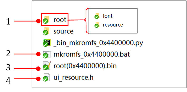
Before starting, select the appropriate demo under the sdk directory ( \subsys\gui\realgui\example\screen_800_480\root_image_800_480 ), or create a new packaging directory based on the example.
Then copy the .bat and .py scripts to that directory. Ensure that the root folder, as well as the .bat and .py scripts, are all located in this directory.
The user data generation process is as follows:

RTL8762G Generate User Data
Copy all generated
.binfiles to the folder\src\app\dashboard\application\root_image\root.In the directory
\src\app\dashboard\application\root_image, double-click the script filemkromfs_0xa00000.batto execute it. This will generate an image of therootfolder. After execution, a new.binfile and a.hfile will appear in this directory.The
.hfile contains the address offset of each file in the file system, allowing direct access without using the file system. Before developing the GUI code, add the folder containing the.hfile to the include directory.The
.binfile is the image file of the root folder. Use the MPTool tool to burn theroot_xx.binfile into the Flash storage.
RTL8763E and RTL8773DO
RTL8763E is the name of a series IC type, including RTL8763EWE-VP/RTL8763EW-VC. The packaging process for RTL8773DO is similar to that of RTL8763E.
Before starting, navigate to the SDK directory ( \tool\Gadgets\gui_package_tool ) and choose the appropriate IC directory. Select the 8763E directory for RTL8763EW and the 87x3D directory for RTL8773DO.
The process for generating user data is as follows:

RTL8763E Generate User Data
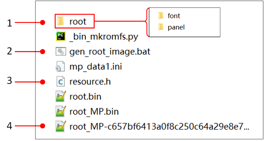
Copy all the generated
.binfiles to the folder\tool\Gadgets\gui_package_tool\8763E\root.Double-click
gen_root_image.batin the\tool\Gadgets\gui_package_tool\8763Edirectory to execute the script and generate an image of the root folder. A new.binfile and.hfile will appear in the directory.The
.hfile contains the address offset of each file in the file system, allowing direct access without using the file system. Before developing the GUI code, add the folder containing the.hfile to the include directory.The
.binfile is the image file of the root folder. Use the MPTool tool to burn theroot_xx.binfile into the Flash storage.
RTL8773E
RTL8773E is the name of a series IC type, including RTL8773EWE/RTL8773EWE-VP. The user data packaging process is as follows:
Generate Root Bin
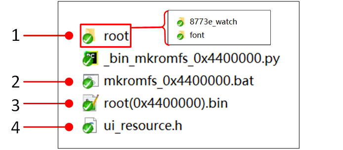
Copy generated images
.binto this folder\src\app\watch\gui_application\root_image\root\8773e_watchand Copy generated font.binto this folder\src\app\watch\gui_application\root_image\root\font.Modify build address: You need to adjust the address to
0x238b400by modifying this filemkromfs_0x4400000.bat( python_bin_mkromfs_0x4400000.py --binary --addr 0x238b400 root root(0x4400000).bin). The--addrcorresponds to the flash map userdata address +0x400 (image header size).Double-click
mkromfs_0x4400000.batin the\src\app\watch\gui_application\root_imagedirectory to execute the script and generate an image of the root folder. A new binroot(0x4400000).binfile and h fileui_resource.hwill appear in the directory.Between them,
.binis the image file of the root folder, and.his the address offset of each file in the file system, which can be accessed directly without using the file system.

RTL8773E Generate User Data
Note
The generated ui_resource.h requires the following code to be added manually.
#if defined _WIN32
#else
#include "flash_map.h"

#define   MUSIC_NAME_BIN_ADDR       APP_DEFINED_SECTION_ADDR
#define   MUSIC_HEADER_BIN_ADDR     (MUSIC_NAME_BIN_ADDR + 0xA000)
#define   MUSIC_NAME_BIN_SIZE       (MUSIC_HEADER_BIN_ADDR - MUSIC_NAME_BIN_ADDR)
#define   MUSIC_HEADER_BIN_SIZE     0x5000
#endif
Adding Header Information
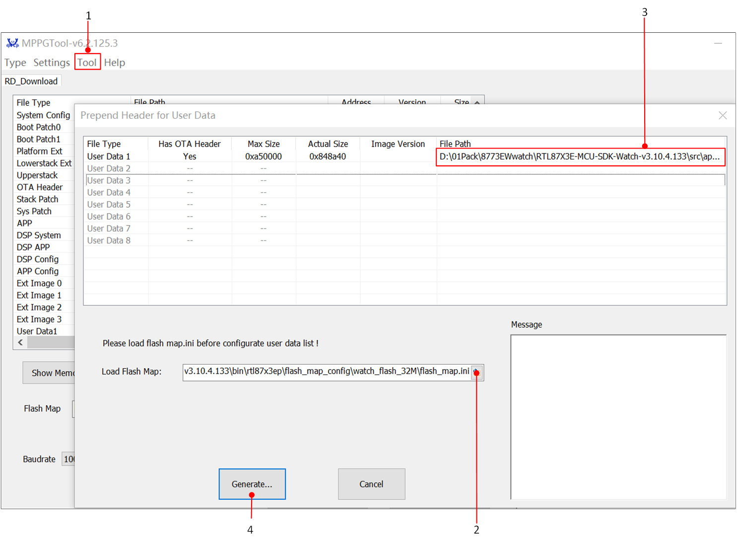
Using the MPPG Tool to add header information to user data files, the process is as follows:

MPPG Tool Add Header Information
In the menu, select .
Add the path to
flash_map.ini.Add the path to the user data file (
root_xx.bin).Generate the burnable user data file.
Note
The Max size must be larger than the Actual size; otherwise, the user data size in the flash_map needs to be changed.